EP1908990A2 - Dispositif de transformation d'un mouvement rotatif en mouvement axial - Google Patents
Dispositif de transformation d'un mouvement rotatif en mouvement axial Download PDFInfo
- Publication number
- EP1908990A2 EP1908990A2 EP07019397A EP07019397A EP1908990A2 EP 1908990 A2 EP1908990 A2 EP 1908990A2 EP 07019397 A EP07019397 A EP 07019397A EP 07019397 A EP07019397 A EP 07019397A EP 1908990 A2 EP1908990 A2 EP 1908990A2
- Authority
- EP
- European Patent Office
- Prior art keywords
- threaded spindle
- nut
- drive
- cage
- rotary encoder
- Prior art date
- Legal status (The legal status is an assumption and is not a legal conclusion. Google has not performed a legal analysis and makes no representation as to the accuracy of the status listed.)
- Withdrawn
Links
- 230000001131 transforming effect Effects 0.000 title 1
- 238000005096 rolling process Methods 0.000 claims abstract description 20
- 238000006073 displacement reaction Methods 0.000 claims description 8
- 238000003801 milling Methods 0.000 abstract 1
- 230000001105 regulatory effect Effects 0.000 description 3
- 238000006243 chemical reaction Methods 0.000 description 2
- 230000001276 controlling effect Effects 0.000 description 2
- 230000001419 dependent effect Effects 0.000 description 1
- 230000000694 effects Effects 0.000 description 1
Images

Classifications
-
- F—MECHANICAL ENGINEERING; LIGHTING; HEATING; WEAPONS; BLASTING
- F16—ENGINEERING ELEMENTS AND UNITS; GENERAL MEASURES FOR PRODUCING AND MAINTAINING EFFECTIVE FUNCTIONING OF MACHINES OR INSTALLATIONS; THERMAL INSULATION IN GENERAL
- F16H—GEARING
- F16H25/00—Gearings comprising primarily only cams, cam-followers and screw-and-nut mechanisms
- F16H25/18—Gearings comprising primarily only cams, cam-followers and screw-and-nut mechanisms for conveying or interconverting oscillating or reciprocating motions
- F16H25/20—Screw mechanisms
- F16H25/22—Screw mechanisms with balls, rollers, or similar members between the co-operating parts; Elements essential to the use of such members
- F16H25/2247—Screw mechanisms with balls, rollers, or similar members between the co-operating parts; Elements essential to the use of such members with rollers
- F16H25/2252—Planetary rollers between nut and screw
Definitions
- the invention relates to a device for converting a rotational movement into an axial movement, or vice versa, with the features in the preamble of claim 1.
- Wälzgewindetriebe For the conversion of rotational movements in axial movements with high efficiency Wälzgewindetriebe are often used, which have a threaded spindle, a surrounding nut and arranged therebetween rolling elements.
- the rolling motion of such Wälzgewinderiose between the mother, the rolling elements and the threaded spindle is comparable to about the movement of the individual elements of a friction gear.
- a friction gear so creates a slip even in said Wälzgewindetrieben.
- slippage has no effect on the motion conversion.
- DE 37 39 059 A1 and DE 28 07 952 A1 known slip causes the slip a change in the effective slope. This can be explained as follows.
- the pitch of the threaded spindle is not modeled by the mother, but by the offset of the fine grooves of rolling elements to rolling elements. Therefore, not the relative rotation from mother to threaded spindle for the feed decisive, but the relative rotational movement between the cage of the rolling elements and the threaded spindle.
- the relative speeds between the components of this screw, that is between the mother, the cage of the rolling elements and the spindle, are dependent on the slip. Such slip would be in a screw according to DE 37 39 059 A1 lead to a positioning error.
- EP 168942 A1 and DE 195 40 634 C1 is a suggestion to prevent a positioning error visible.
- the planet cage is designed as a mother.
- the actual nut sits in the cage and is rotatably supported by a thrust bearing.
- a disadvantage of such a design with driven planetary cage is that in addition to the thrust bearing, which is anyway necessary to support the screw drive, an additional thrust bearing is still present in the mother. This additional bearing requires additional space and generates additional loss friction, which degrades the overall efficiency.
- the invention has for its object to provide a device for converting a rotational movement in an axial movement, which offers the ability to compensate for a slip, without an additional thrust bearing in the mother and otherwise easy, compact and inexpensive.
- An advantageous embodiment provides a regulated drive, which uses the signal of the measuring device for controlling the axial movement. It may be advantageous if the drive rotatably rotatably and axially displaceably held threaded spindle drives the nut or if instead the drive rotatably and axially displaceably held nut rotatably drives the threaded spindle. In the former case of the rotatably driven nut, it may be advantageous if the measuring device has an engaging on the cage of the rolling or rolling body, the rotational movement of this cage detecting rotary encoder whose output signal is a measure of the axial displacement of the threaded spindle. This results in the advantage that the mother and thus also the cage remain stationary and in a simple way the encoder can be attached to the cage. Since the threaded spindle does not rotate, the rotary encoder provides the relative movement directly.
- the measuring device has an engaging on the cage of the rolling or rolling body, the rotational movement detecting encoder and further comprises a rotary movement of the threaded spindle detecting rotary encoder, wherein the Difference of the output signals of both encoders is a measure of the axial displacement of the nut.
- the rotary encoder detecting the rotational movement of the threaded spindle can in this case be formed in a particularly simple manner by the motor rotary encoder of the drive.
- a device 10 is shown schematically, which is suitable for converting a rotational movement into an axial movement, or vice versa.
- the device 10 has a drive 11, which may be designed, for example, as a regulated drive and, in particular, as an electric servomotor, for example. Other embodiments of such a drive 11 are within the scope of the invention.
- the device 10 further comprises a screw drive 12 of known type ( DE 37 39 059 A1 ), with a threaded spindle 13, a threaded spindle 13 surrounding the nut 14 with internal profiling and arranged in the radial direction between the threaded spindle 13 and the nut 14 profiled Wälz- or rolling bodies 15 which are rotatably received end in rotatable cages 16.
- a screw drive 12 of known type ( DE 37 39 059 A1 ), with a threaded spindle 13, a threaded spindle 13 surrounding the nut 14 with internal profiling and arranged in the radial direction between the threaded spindle 13 and the nut 14 profiled Wälz- or rolling bodies 15 which are rotatably received end in rotatable cages 16.
- the device 10 has a measuring device 20, which measures the differential rotational movement between the cage 16 and the threaded spindle 13 as a measure of the axial movement between the threaded spindle 13 and the nut 14.
- the drive 11 may be a controlled drive, the output of the measuring device 20th used for the control of the axial movement.
- the threaded spindle 13 is held non-rotatably and guided axially displaceable in the direction of arrow 17.
- the nut 14 is rotatably driven by the drive 11.
- the drive 11 has a hollow shaft 18, with which the nut 14 is connected to the rotational drive, for example by means of indicated screws 19.
- the threaded spindle 13 is secured against rotation and guided linearly in the direction of arrow 17.
- the nut 14 and the cage 16 are fixed with respect to the sliding threaded spindle 13.
- the measuring device 20 has a rotary encoder 21 which acts on the cage 16 and detects its rotational movement.
- the output signal of the rotary encoder 21 is a measure of the axial displacement of the threaded spindle 13.
- This output signal Sact of the rotary encoder 21 is fed directly to a desired-actual comparison and the resulting control deviation of a schematically indicated control device 22, e.g. is formed of a servo regulator and its output to the drive 11, e.g. in the form of a servo motor, is guided.
- the device 10 according to the first embodiment in FIGS. 1 and 2 is particularly simple, compact and inexpensive.
- the nut 14 and the cage 16 remain stationary, the encoder 21, which acts on the cage 16, also remains stationary. Since the threaded spindle 13 does not rotate, the rotary encoder 21 directly supplies an output signal as a measure of the axial displacement of the threaded spindle 13.
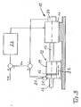
- the second embodiment of FIG. 3 differs from the first embodiment in that in Fig. 3, the threaded spindle 13 from. Drive 11 is rotatably driven and the nut 14 secured against rotation and held non-rotatably and thereby axially displaceable in the direction of arrow 23. Also in this embodiment, the measuring device 20 is designed so that this measures the differential rotational movement between the cage 16 and the threaded spindle 13 as a measure for the axial movement between the threaded spindle 13 and the nut 14.
- the controlled drive 11 uses the signal of the measuring device 20 for controlling the axial movement in the direction of arrow 23.
- the measuring device 20 has a further rotary encoder 24, which detects the rotational movement of the threaded spindle 13.
- This second rotary encoder 24 may be arranged at any suitable location where it can detect the rotational movement of the threaded spindle 13. It may be advantageous if this rotary encoder is formed by the motor rotary encoder of the controlled drive 11, for example in the form of a servomotor.
- the output signals of both rotary encoders 21 and 24 are processed, wherein the difference between these two output signals is a measure of the axial displacement of the nut 14 in the direction of arrow 23.
- This actual value Sist of the axial displacement of the nut 14 is supplied to a desired-actual comparison, the resulting control deviation being supplied to a control device 22, for example in the form of a servo regulator, which is in communication with the drive 11 or, as in the first embodiment, also a component of the trained as a servomotor drive 11 may be.
- a control device 22 for example in the form of a servo regulator, which is in communication with the drive 11 or, as in the first embodiment, also a component of the trained as a servomotor drive 11 may be.
Landscapes
- Engineering & Computer Science (AREA)
- General Engineering & Computer Science (AREA)
- Mechanical Engineering (AREA)
- Transmission Devices (AREA)
Applications Claiming Priority (1)
| Application Number | Priority Date | Filing Date | Title |
|---|---|---|---|
| DE102006047790.1A DE102006047790B4 (de) | 2006-10-06 | 2006-10-06 | Vorrichtung zur Umwandlung einer Drehbewegung in eine Axialbewegung |
Publications (2)
| Publication Number | Publication Date |
|---|---|
| EP1908990A2 true EP1908990A2 (fr) | 2008-04-09 |
| EP1908990A3 EP1908990A3 (fr) | 2009-09-30 |
Family
ID=38890990
Family Applications (1)
| Application Number | Title | Priority Date | Filing Date |
|---|---|---|---|
| EP07019397A Withdrawn EP1908990A3 (fr) | 2006-10-06 | 2007-10-04 | Dispositif de transformation d'un mouvement rotatif en mouvement axial |
Country Status (2)
| Country | Link |
|---|---|
| EP (1) | EP1908990A3 (fr) |
| DE (1) | DE102006047790B4 (fr) |
Cited By (4)
| Publication number | Priority date | Publication date | Assignee | Title |
|---|---|---|---|---|
| DE102009040606A1 (de) | 2009-09-08 | 2011-03-17 | Schaeffler Technologies Gmbh & Co. Kg | Planetenwälzgetriebe |
| WO2011050766A1 (fr) * | 2009-10-29 | 2011-05-05 | Schaeffler Technologies Gmbh & Co. Kg | Actionneur d'embrayage hydrostatique |
| WO2011050767A1 (fr) * | 2009-10-29 | 2011-05-05 | Schaeffler Technologies Gmbh & Co. Kg | Actionneur hydrostatique |
| CN114744820A (zh) * | 2022-04-29 | 2022-07-12 | 中国科学院沈阳自动化研究所 | 一种基于编码器位置反馈的水下电动直线缸机构 |
Citations (4)
| Publication number | Priority date | Publication date | Assignee | Title |
|---|---|---|---|---|
| DE2807952A1 (de) | 1978-02-24 | 1979-08-30 | Peter Ing Grad Langos | Rollen-umlauf-spindelsystem |
| EP0168942A1 (fr) | 1984-06-13 | 1986-01-22 | Illinois Tool Works Inc. | Assemblage de vis sans fin et écrou |
| DE3739059A1 (de) | 1987-11-17 | 1989-05-24 | Deutsche Forsch Luft Raumfahrt | Vorrichtung zur umwandlung einer drehbewegung in eine axialbewegung |
| DE19540634C1 (de) | 1995-10-31 | 1997-03-13 | Deutsche Forsch Luft Raumfahrt | Vorrichtung zur Umwandlung einer Dreh- in eine Axialbewegung |
Family Cites Families (4)
| Publication number | Priority date | Publication date | Assignee | Title |
|---|---|---|---|---|
| NL1006540C2 (nl) * | 1997-07-10 | 1999-01-15 | Skf Ind Trading & Dev | Elektrische actuator met regelsensor, alsmede schijfrem omvattende een dergelijke actuator. |
| DE10011859C2 (de) * | 2000-03-10 | 2002-05-29 | Carsten Winter | Einpressvorrichtung |
| DE102004054037B3 (de) * | 2004-11-05 | 2006-10-05 | Stabilus Gmbh | Verstellvorrichtung |
| DE102005017476B4 (de) * | 2005-04-16 | 2007-09-06 | Abel Gmbh & Co. Kg | Kolbenmembran- bzw. Kolbenpumpe |
-
2006
- 2006-10-06 DE DE102006047790.1A patent/DE102006047790B4/de active Active
-
2007
- 2007-10-04 EP EP07019397A patent/EP1908990A3/fr not_active Withdrawn
Patent Citations (4)
| Publication number | Priority date | Publication date | Assignee | Title |
|---|---|---|---|---|
| DE2807952A1 (de) | 1978-02-24 | 1979-08-30 | Peter Ing Grad Langos | Rollen-umlauf-spindelsystem |
| EP0168942A1 (fr) | 1984-06-13 | 1986-01-22 | Illinois Tool Works Inc. | Assemblage de vis sans fin et écrou |
| DE3739059A1 (de) | 1987-11-17 | 1989-05-24 | Deutsche Forsch Luft Raumfahrt | Vorrichtung zur umwandlung einer drehbewegung in eine axialbewegung |
| DE19540634C1 (de) | 1995-10-31 | 1997-03-13 | Deutsche Forsch Luft Raumfahrt | Vorrichtung zur Umwandlung einer Dreh- in eine Axialbewegung |
Cited By (8)
| Publication number | Priority date | Publication date | Assignee | Title |
|---|---|---|---|---|
| DE102009040606A1 (de) | 2009-09-08 | 2011-03-17 | Schaeffler Technologies Gmbh & Co. Kg | Planetenwälzgetriebe |
| DE102009040606B4 (de) * | 2009-09-08 | 2015-08-13 | Schaeffler Technologies AG & Co. KG | Planetenwälzgetriebe |
| WO2011050766A1 (fr) * | 2009-10-29 | 2011-05-05 | Schaeffler Technologies Gmbh & Co. Kg | Actionneur d'embrayage hydrostatique |
| WO2011050767A1 (fr) * | 2009-10-29 | 2011-05-05 | Schaeffler Technologies Gmbh & Co. Kg | Actionneur hydrostatique |
| CN102575729A (zh) * | 2009-10-29 | 2012-07-11 | 舍弗勒技术股份两合公司 | 静压致动器 |
| US8490391B2 (en) | 2009-10-29 | 2013-07-23 | Schaeffler Technologies AG & Co. KG | Hydrostatic clutch actuator |
| CN102575729B (zh) * | 2009-10-29 | 2015-11-25 | 舍弗勒技术股份两合公司 | 静压致动器 |
| CN114744820A (zh) * | 2022-04-29 | 2022-07-12 | 中国科学院沈阳自动化研究所 | 一种基于编码器位置反馈的水下电动直线缸机构 |
Also Published As
| Publication number | Publication date |
|---|---|
| DE102006047790B4 (de) | 2015-10-15 |
| DE102006047790A1 (de) | 2008-04-10 |
| EP1908990A3 (fr) | 2009-09-30 |
Similar Documents
| Publication | Publication Date | Title |
|---|---|---|
| DE102011003485B4 (de) | Kugelgewindetrieb und damit ausgestattete Lenkeinrichtung | |
| DE102019103384A1 (de) | Planetenwälzgewindetrieb | |
| DE3241350A1 (de) | Vorrichtung zur umwandlung einer drehbewegung in eine linearbewegung | |
| EP1820982B1 (fr) | Dispositif de guidage linéaire doté d'un dispositif de réglage de pré-tension | |
| EP3464947B1 (fr) | Dispositif de réglage et utilisation dudit dispositif de réglage | |
| DE4103160A1 (de) | Falzapparat mit einer vorrichtung zum verstellen von verstellbaren elementen eines falzwerkzylinders | |
| DE3610284A1 (de) | Antriebsmechanismus mit einer gewindespindel und spindelmutter | |
| DE102020103422A1 (de) | Planetenwälzgewindetrieb | |
| EP1908990A2 (fr) | Dispositif de transformation d'un mouvement rotatif en mouvement axial | |
| EP4728208A1 (fr) | Actionneur pour fournir un couple, ledit actionneur comprenant un entraînement linéaire | |
| EP2398698B1 (fr) | Entraînement de bateau comportant un dispositif de commande | |
| DE102007022715A1 (de) | Presse | |
| EP1601522A1 (fr) | Dispositif de presse electrique | |
| DE102012203553A1 (de) | Übersetzungsgetriebe | |
| DE102023120475B4 (de) | Antriebsvorrichtung für einen Roboter sowie Roboter mit einer solchen Antriebsvorrichtung | |
| EP3523556A1 (fr) | Transmission ainsi qu'appuie-tête pourvu d'au moins un entraînement électrique, comprenant une transmission | |
| DE102010029242A1 (de) | Führungseinrichtung und Werkzeugmaschine mit einer derartigen Führungseinrichtung | |
| DE20213391U1 (de) | Verstellvorrichtung | |
| DE102018126071A1 (de) | Linearaktor, insbesondere für eine Fahrzeugkupplung | |
| DE102011085550A1 (de) | Aktuator zur Umsetzung einer rotativen Bewegung in eine lineare Bewegung | |
| EP3765244B1 (fr) | Articulation avec profilé multifonctionnel pour manipulateur | |
| DE102010018210A1 (de) | Vorrichtung zur Verstellung der Drehwinkellage einer Welle | |
| EP3500776B1 (fr) | Mécanisme d'entraînement à broche ayant un embrayage de surcharge | |
| DE10222995C1 (de) | Verstellantrieb für Kraftfahrzeugsitzteile | |
| DE102013221349A1 (de) | Antriebseinheit |
Legal Events
| Date | Code | Title | Description |
|---|---|---|---|
| PUAI | Public reference made under article 153(3) epc to a published international application that has entered the european phase |
Free format text: ORIGINAL CODE: 0009012 |
|
| AK | Designated contracting states |
Kind code of ref document: A2 Designated state(s): AT BE BG CH CY CZ DE DK EE ES FI FR GB GR HU IE IS IT LI LT LU LV MC MT NL PL PT RO SE SI SK TR |
|
| AX | Request for extension of the european patent |
Extension state: AL BA HR MK RS |
|
| PUAL | Search report despatched |
Free format text: ORIGINAL CODE: 0009013 |
|
| AK | Designated contracting states |
Kind code of ref document: A3 Designated state(s): AT BE BG CH CY CZ DE DK EE ES FI FR GB GR HU IE IS IT LI LT LU LV MC MT NL PL PT RO SE SI SK TR |
|
| AX | Request for extension of the european patent |
Extension state: AL BA HR MK RS |
|
| 17P | Request for examination filed |
Effective date: 20091125 |
|
| 17Q | First examination report despatched |
Effective date: 20010128 |
|
| R17C | First examination report despatched (corrected) |
Effective date: 20100128 |
|
| AKX | Designation fees paid |
Designated state(s): AT BE BG CH CY CZ DE DK EE ES FI FR GB GR HU IE IS IT LI LT LU LV MC MT NL PL PT RO SE SI SK TR |
|
| 17Q | First examination report despatched |
Effective date: 20110419 |
|
| GRAP | Despatch of communication of intention to grant a patent |
Free format text: ORIGINAL CODE: EPIDOSNIGR1 |
|
| STAA | Information on the status of an ep patent application or granted ep patent |
Free format text: STATUS: THE APPLICATION IS DEEMED TO BE WITHDRAWN |
|
| 18D | Application deemed to be withdrawn |
Effective date: 20120322 |