EP1908986A2 - Coussinet élastique avec amortissement hydraulique - Google Patents
Coussinet élastique avec amortissement hydraulique Download PDFInfo
- Publication number
- EP1908986A2 EP1908986A2 EP07019118A EP07019118A EP1908986A2 EP 1908986 A2 EP1908986 A2 EP 1908986A2 EP 07019118 A EP07019118 A EP 07019118A EP 07019118 A EP07019118 A EP 07019118A EP 1908986 A2 EP1908986 A2 EP 1908986A2
- Authority
- EP
- European Patent Office
- Prior art keywords
- chamber
- channel
- contour
- sub
- flow
- Prior art date
- Legal status (The legal status is an assumption and is not a legal conclusion. Google has not performed a legal analysis and makes no representation as to the accuracy of the status listed.)
- Granted
Links
Images


Classifications
-
- F—MECHANICAL ENGINEERING; LIGHTING; HEATING; WEAPONS; BLASTING
- F16—ENGINEERING ELEMENTS AND UNITS; GENERAL MEASURES FOR PRODUCING AND MAINTAINING EFFECTIVE FUNCTIONING OF MACHINES OR INSTALLATIONS; THERMAL INSULATION IN GENERAL
- F16F—SPRINGS; SHOCK-ABSORBERS; MEANS FOR DAMPING VIBRATION
- F16F13/00—Units comprising springs of the non-fluid type as well as vibration-dampers, shock-absorbers, or fluid springs
- F16F13/04—Units comprising springs of the non-fluid type as well as vibration-dampers, shock-absorbers, or fluid springs comprising both a plastics spring and a damper, e.g. a friction damper
- F16F13/06—Units comprising springs of the non-fluid type as well as vibration-dampers, shock-absorbers, or fluid springs comprising both a plastics spring and a damper, e.g. a friction damper the damper being a fluid damper, e.g. the plastics spring not forming a part of the wall of the fluid chamber of the damper
- F16F13/08—Units comprising springs of the non-fluid type as well as vibration-dampers, shock-absorbers, or fluid springs comprising both a plastics spring and a damper, e.g. a friction damper the damper being a fluid damper, e.g. the plastics spring not forming a part of the wall of the fluid chamber of the damper the plastics spring forming at least a part of the wall of the fluid chamber of the damper
- F16F13/14—Units of the bushing type, i.e. loaded predominantly radially
- F16F13/1463—Units of the bushing type, i.e. loaded predominantly radially characterised by features of passages between working chambers
Definitions
- the invention relates to an elastic bushing with hydraulic damping, in particular for bearings in a motor vehicle or as a machine bearing according to the preamble of claim 1.
- Known generic elastic bushings with hydraulic damping consist of an inner part for connection to a first component to be supported and an outer tube and of an elastomeric body between the inner part and the outer tube.
- bearing bushes on two radially opposite, filled with hydraulic fluid working chambers, which are formed by associated recesses in the outer tube and in the elastomer body and by a liquid-tight final outer sleeve. The two working chambers are interconnected by a flow channel.
- Object of the invention is in contrast to develop a generic elastic bushing with hydraulic damping so that it is inexpensive to produce with a simple structure and good function and has a long flow channel.
- an elastomer layer is applied to the outer tube radially outward, in which the flow channel are formed with its channel bottom and the channel side walls and a transition contour chamber, wherein the flow channel and the transition contour chamber are bounded radially outside of the outer sleeve liquid-tight.
- the flow channel consists of two channel parts, of which in each case a channel part extends laterally next to the working chambers in a transverse plane in such a way
- the first subchannel is connected to the first working chamber via a first lateral chamber outlet opening, passes in the circumferential direction next to the first working chamber and the second working chamber and opens into the transitional contour chamber.
- the second subchannel is connected to the second working chamber via a second lateral chamber outlet opening and runs alongside the second working chamber and the first working chamber in the opposite circumferential direction, after which it also opens into the transitional contour chamber.
- the flow connection of the axially opposite sub-channels is made.
- the elastic bushing according to the invention contains a desired long flow channel and is simple in construction, and easy and inexpensive to manufacture, since no additional complex components, such. B. channel support are required.
- the bearing part consisting of the inner part, the outer tube and the elastomer material is easy to remove in the vertical direction from a horizontally split shape during production, since there are no undercuts in the flow channel course and flow guidance contours in the transition contour chamber can be easily demoulded, with an additional Flow favorable influencing geometry is einformbar.
- the transition contour chamber has a larger cross-section than the sub-channels, so that this is an extension relative to the sub-channels.
- the oscillating liquid mass is advantageously further increased to achieve a suitable damping behavior.
- a flow guidance contour can be formed between the opening sub-channels, with which the flow of the fluid can be positively influenced in the sense of a suitable damping behavior.
- the transition contour chamber at least partially as a cylindrical portion, wherein the portion surface is located in the Entformides.
- the bearing bush is pressed into a receiving eye of the second component to be stored, such as a cab of a truck, with approximately horizontal bushing axis and vertically superimposed working chambers. A built-in bushing is then suitable for a damped elastic support vertical loads.
- the upper limit (based on the above-mentioned mounting position) of the current-carrying contour in the transition contour chamber have a flow-optimized curve between the junction of the first sub-channel and the second sub-channel. The demolding is guaranteed.
- the transitional contour chamber may be formed approximately below the junction of the second sub-channel vertically aligned longitudinal slats whose upper connecting line corresponds to a lower limit of the current-carrying contour optionally in conjunction with the flow-optimized curve above the upper limit.
- the use of longitudinal lamellae makes it possible to replicate a suitable current-carrying channel, the mold being able to be removed from mold by the vertical orientation of the longitudinal lamellae.
- the longitudinal lamellae can also be set slightly obliquely, in particular in the flow direction, as a result of which demoldability is likewise still present.
- one or more flow-conducting contour elements can be subsequently attached in a form-fitting and / or force-fitting manner after demoulding. This allows further adaptation and coordination to specific circumstances.
- the inner part is approximately conically tapered downwards in cross-section corresponding to a pipe or cone bearing.
- the inner part is made of plastic with a central bore for receiving a pivot axis.
- a warehouse is u. a. well suited to support the cab of a truck.
- an elastic bushing 1 which consists of an inner part 2, an outer tube 3 and an elastomeric body 4 between the inner part 2 and the outer tube 3.
- FIG. 1 two radially opposite, filled with hydraulic fluid working chambers are formed (upper working chamber 5 and lower working chamber 6), which are made by associated recesses in the outer tube 3 and in the elastomer body 4 and by a liquid-tight final outer sleeve 7.
- the working chambers 5, 6 are limited with respect to the elastomeric material to the respective chamber bottoms of the two-sided strongly dimensioned elastomer packages and in the side regions of the retracted to the center of the thin-walled elastomer walls 8.
- Due to the recesses on the outer tube 3 in the region of the working chambers 5, 6 are in Fig. 1, only opposite annular peripheral side portions of the outer tube 3 and correspond in Fig. 2, only the molded circumferential annular regions of the outer tube 3 visible.
- an elastomer layer 9 is radially outwardly applied, in which a flow channel 10 are formed with its two sub-channels 10a, 10b and a transition contour chamber 11, wherein the sub-channels 10a, 10b and the transition contour chamber 11 are bounded radially outside of the outer sleeve 7 liquid-tight ,
- the inner part 2 On the inner part 2, opposing, coated with elastomeric material 13 stops 14 are integrally formed in an axially central region, each projecting radially into the working chambers 5, 6.
- the inner part 2 is tapered conically downwards in cross section. It is preferably made of plastic with a central bore 15 for receiving a metallic pivot axis.
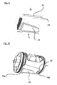
- Fig. 3 is a perspective view of the elastic bushing 1, but without the outer sleeve 7 is shown. There are clearly the inner part 2, the upper working chamber 5 with the upper stop 14, as well as the front side circumferential annular regions 16 and 17 with the sealing lips for the outer sleeve 7 recognizable.
- the elastomer layer 9 can be seen, in which the sub-channels 10a, 10b and the transition contour chamber 11 are formed.
- the sub-channels 10a and 10b each extend laterally adjacent to the working chambers 5 and 6.
- the sub-channel 10b is connected to the upper working chamber 5 via a lateral chamber outlet opening 18b. From there, the sub-channel 10b runs past the upper working chamber 5 and the lower working chamber 6 in the circumferential direction and opens at the junction 19b into the transition contour chamber 11.
- the other subchannel 10a begins at a chamber outlet opening 18a (not visible in FIG. 3) of the lower working chamber 6 and runs in the opposite circumferential direction as far as the junction 19a into the transitional chamber 11 next to the lower working chamber 6 and the upper working chamber 5 Transitional contour chamber 11, the flow connection between the sub-channels 10a, 10b and their junctions 19a, 19b made.
- FIGS. 3 to 10 show different embodiments of the transition contour chamber and the flow-influencing contours contained therein: In all the embodiments of a transition contour chamber 11 shown, this is formed at least partially as a cylindrical section with a vertically projecting section surface.
- the upper limit 20 of the current-carrying contour has in all embodiments a flow-optimized curve between the junctions 19a and 19b.
- longitudinally aligned longitudinal laminations 21 are formed below and laterally to the junction 19a in the lower region of the transitional contour chamber 11, the upper connecting line of which corresponds to a lower boundary of the flow guidance contour approximately parallel to the upper boundary 20.
- the longitudinal lamellae 21 are set somewhat obliquely in the flow direction from the junction 19b to the junction 19a.
- Fig. 7 it is indicated that, depending on the circumstances, other flow-conducting elevations and / or depressions can be attached in order to optimize the flow path.
- Fig. 8 are also in cross section specified different structures that can be used as needed and optimization.
- a flow-conducting contour element is subsequently attached in a form-fitting manner in the transition contour chamber 11 after removal from the mold. As can be seen from FIG. 9, the latter is positively inserted into a dovetail guide 23 in the removal direction.
Landscapes
- Engineering & Computer Science (AREA)
- General Engineering & Computer Science (AREA)
- Mechanical Engineering (AREA)
- Combined Devices Of Dampers And Springs (AREA)
Applications Claiming Priority (1)
| Application Number | Priority Date | Filing Date | Title |
|---|---|---|---|
| DE102006047446A DE102006047446A1 (de) | 2006-10-07 | 2006-10-07 | Elastische Lagerbuchse mit hydraulischer Dämpfung |
Publications (3)
| Publication Number | Publication Date |
|---|---|
| EP1908986A2 true EP1908986A2 (fr) | 2008-04-09 |
| EP1908986A3 EP1908986A3 (fr) | 2010-07-07 |
| EP1908986B1 EP1908986B1 (fr) | 2011-09-28 |
Family
ID=38984224
Family Applications (1)
| Application Number | Title | Priority Date | Filing Date |
|---|---|---|---|
| EP07019118A Not-in-force EP1908986B1 (fr) | 2006-10-07 | 2007-09-28 | Coussinet élastique avec amortissement hydraulique |
Country Status (3)
| Country | Link |
|---|---|
| EP (1) | EP1908986B1 (fr) |
| AT (1) | ATE526515T1 (fr) |
| DE (1) | DE102006047446A1 (fr) |
Family Cites Families (6)
| Publication number | Priority date | Publication date | Assignee | Title |
|---|---|---|---|---|
| JP2583212B2 (ja) * | 1985-05-27 | 1997-02-19 | 日産自動車株式会社 | 振動減衰装置 |
| FR2669091B1 (fr) * | 1990-11-13 | 1995-02-17 | Hutchinson | Perfectionnements apportes aux manchons antivibratoires hydrauliques. |
| JPH0642577A (ja) * | 1992-07-23 | 1994-02-15 | Marugo Rubber Kogyo Kk | 液封マウント装置 |
| JPH06346943A (ja) * | 1993-06-10 | 1994-12-20 | Kurashiki Kako Co Ltd | 液体封入式防振装置 |
| DE4320643C2 (de) * | 1993-06-22 | 1997-02-06 | Hubert Dipl Ing Bruehl | Hydraulisch dämpfendes Buchsenlager |
| DE4332367C2 (de) * | 1993-09-23 | 1995-10-12 | Lemfoerder Metallwaren Ag | Hülsengummifeder für Lagerungen in einem Kraftfahrzeug |
-
2006
- 2006-10-07 DE DE102006047446A patent/DE102006047446A1/de not_active Withdrawn
-
2007
- 2007-09-28 AT AT07019118T patent/ATE526515T1/de active
- 2007-09-28 EP EP07019118A patent/EP1908986B1/fr not_active Not-in-force
Also Published As
| Publication number | Publication date |
|---|---|
| EP1908986B1 (fr) | 2011-09-28 |
| DE102006047446A1 (de) | 2008-04-10 |
| ATE526515T1 (de) | 2011-10-15 |
| EP1908986A3 (fr) | 2010-07-07 |
Similar Documents
| Publication | Publication Date | Title |
|---|---|---|
| EP1162338B1 (fr) | Dispositif d'amortisseur de chocs, en particulier pour portes de meubles et tiroirs | |
| DE102005046407B4 (de) | Motorabdeckung | |
| DE3039801A1 (de) | Kolben fuer ein pneumatisches, hydraulisches oder hydropneumatisches aggregat | |
| DE10347533B4 (de) | Lineare Führungsvorrichtung und Verfahren zur Montage derselben | |
| EP3737875B1 (fr) | Coussinet de palier hydraulique | |
| EP1561968B1 (fr) | Rail de tension ou de guidage avec canalisation pour installation | |
| DE19529168A1 (de) | Hydraulischer Türschließer und Verfahren zum Herstellen desselben | |
| EP1611367A1 (fr) | Palier a douille en caoutchouc a amortissement hydraulique pour un montage vertical | |
| DE10135931A1 (de) | Motorradrahmen | |
| EP1908987A2 (fr) | Coussinet élastique avec amortissement hydraulique | |
| EP1908986B1 (fr) | Coussinet élastique avec amortissement hydraulique | |
| DE102004014328B4 (de) | Hydraulisch dämpfendes Gummilager | |
| DE102005009348A1 (de) | Anpassungsfähiges Gleitlager für Teleskopkranausleger | |
| DE102005054852A1 (de) | Hydrolager und Verfahren zur Herstellung eines Hydrolagers | |
| DE102013006196B4 (de) | Saugrohr für Gas einer Brennkraftmaschine mit einer Klappeneinheit | |
| EP1908988B1 (fr) | Tube extérieur pour un coussinet élastique à amortissement hydraulique | |
| EP2058551B1 (fr) | Coussinet élastique avec amortissement hydraulique | |
| DE102005003552B4 (de) | Kreuzkopfmotor | |
| DE102005004997A1 (de) | Pedal für Kraftfahrzeuge | |
| DE19936956B4 (de) | Verfahren zum Herstellen eines Kunststofformteils | |
| EP2058550B1 (fr) | Coussinet élastique avec amortissement hydraulique | |
| DE102005054851A1 (de) | Hydrolager und Verfahren zur Herstellung eines Hydrolagers | |
| DE102011012312A1 (de) | Schwingungsdämpfer für ein Kraftfahrzeug | |
| DE10314242A1 (de) | Servozylinder | |
| EP1900979A1 (fr) | Système d'étanchéification entre deux composants |
Legal Events
| Date | Code | Title | Description |
|---|---|---|---|
| PUAI | Public reference made under article 153(3) epc to a published international application that has entered the european phase |
Free format text: ORIGINAL CODE: 0009012 |
|
| AK | Designated contracting states |
Kind code of ref document: A2 Designated state(s): AT BE BG CH CY CZ DE DK EE ES FI FR GB GR HU IE IS IT LI LT LU LV MC MT NL PL PT RO SE SI SK TR |
|
| AX | Request for extension of the european patent |
Extension state: AL BA HR MK RS |
|
| PUAL | Search report despatched |
Free format text: ORIGINAL CODE: 0009013 |
|
| AK | Designated contracting states |
Kind code of ref document: A3 Designated state(s): AT BE BG CH CY CZ DE DK EE ES FI FR GB GR HU IE IS IT LI LT LU LV MC MT NL PL PT RO SE SI SK TR |
|
| AX | Request for extension of the european patent |
Extension state: AL BA HR MK RS |
|
| 17P | Request for examination filed |
Effective date: 20110103 |
|
| AKX | Designation fees paid |
Designated state(s): AT BE BG CH CY CZ DE DK EE ES FI FR GB GR HU IE IS IT LI LT LU LV MC MT NL PL PT RO SE SI SK TR |
|
| GRAP | Despatch of communication of intention to grant a patent |
Free format text: ORIGINAL CODE: EPIDOSNIGR1 |
|
| RIC1 | Information provided on ipc code assigned before grant |
Ipc: F16F 13/14 20060101AFI20110307BHEP |
|
| GRAS | Grant fee paid |
Free format text: ORIGINAL CODE: EPIDOSNIGR3 |
|
| GRAA | (expected) grant |
Free format text: ORIGINAL CODE: 0009210 |
|
| AK | Designated contracting states |
Kind code of ref document: B1 Designated state(s): AT BE BG CH CY CZ DE DK EE ES FI FR GB GR HU IE IS IT LI LT LU LV MC MT NL PL PT RO SE SI SK TR |
|
| REG | Reference to a national code |
Ref country code: GB Ref legal event code: FG4D Free format text: NOT ENGLISH |
|
| REG | Reference to a national code |
Ref country code: CH Ref legal event code: EP |
|
| REG | Reference to a national code |
Ref country code: IE Ref legal event code: FG4D |
|
| REG | Reference to a national code |
Ref country code: DE Ref legal event code: R096 Ref document number: 502007008243 Country of ref document: DE Effective date: 20111215 |
|
| REG | Reference to a national code |
Ref country code: NL Ref legal event code: VDEP Effective date: 20110928 |
|
| PG25 | Lapsed in a contracting state [announced via postgrant information from national office to epo] |
Ref country code: SE Free format text: LAPSE BECAUSE OF FAILURE TO SUBMIT A TRANSLATION OF THE DESCRIPTION OR TO PAY THE FEE WITHIN THE PRESCRIBED TIME-LIMIT Effective date: 20110928 Ref country code: FI Free format text: LAPSE BECAUSE OF FAILURE TO SUBMIT A TRANSLATION OF THE DESCRIPTION OR TO PAY THE FEE WITHIN THE PRESCRIBED TIME-LIMIT Effective date: 20110928 Ref country code: LT Free format text: LAPSE BECAUSE OF FAILURE TO SUBMIT A TRANSLATION OF THE DESCRIPTION OR TO PAY THE FEE WITHIN THE PRESCRIBED TIME-LIMIT Effective date: 20110928 |
|
| LTIE | Lt: invalidation of european patent or patent extension |
Effective date: 20110928 |
|
| PG25 | Lapsed in a contracting state [announced via postgrant information from national office to epo] |
Ref country code: CY Free format text: LAPSE BECAUSE OF FAILURE TO SUBMIT A TRANSLATION OF THE DESCRIPTION OR TO PAY THE FEE WITHIN THE PRESCRIBED TIME-LIMIT Effective date: 20110928 Ref country code: LV Free format text: LAPSE BECAUSE OF FAILURE TO SUBMIT A TRANSLATION OF THE DESCRIPTION OR TO PAY THE FEE WITHIN THE PRESCRIBED TIME-LIMIT Effective date: 20110928 Ref country code: SI Free format text: LAPSE BECAUSE OF FAILURE TO SUBMIT A TRANSLATION OF THE DESCRIPTION OR TO PAY THE FEE WITHIN THE PRESCRIBED TIME-LIMIT Effective date: 20110928 Ref country code: GR Free format text: LAPSE BECAUSE OF FAILURE TO SUBMIT A TRANSLATION OF THE DESCRIPTION OR TO PAY THE FEE WITHIN THE PRESCRIBED TIME-LIMIT Effective date: 20111229 |
|
| BERE | Be: lapsed |
Owner name: JORN G.M.B.H. Effective date: 20110930 |
|
| REG | Reference to a national code |
Ref country code: IE Ref legal event code: FD4D |
|
| PG25 | Lapsed in a contracting state [announced via postgrant information from national office to epo] |
Ref country code: SK Free format text: LAPSE BECAUSE OF FAILURE TO SUBMIT A TRANSLATION OF THE DESCRIPTION OR TO PAY THE FEE WITHIN THE PRESCRIBED TIME-LIMIT Effective date: 20110928 Ref country code: MC Free format text: LAPSE BECAUSE OF NON-PAYMENT OF DUE FEES Effective date: 20110930 Ref country code: IS Free format text: LAPSE BECAUSE OF FAILURE TO SUBMIT A TRANSLATION OF THE DESCRIPTION OR TO PAY THE FEE WITHIN THE PRESCRIBED TIME-LIMIT Effective date: 20120128 Ref country code: CZ Free format text: LAPSE BECAUSE OF FAILURE TO SUBMIT A TRANSLATION OF THE DESCRIPTION OR TO PAY THE FEE WITHIN THE PRESCRIBED TIME-LIMIT Effective date: 20110928 |
|
| PGFP | Annual fee paid to national office [announced via postgrant information from national office to epo] |
Ref country code: FR Payment date: 20120319 Year of fee payment: 5 |
|
| REG | Reference to a national code |
Ref country code: CH Ref legal event code: PL |
|
| PG25 | Lapsed in a contracting state [announced via postgrant information from national office to epo] |
Ref country code: PT Free format text: LAPSE BECAUSE OF FAILURE TO SUBMIT A TRANSLATION OF THE DESCRIPTION OR TO PAY THE FEE WITHIN THE PRESCRIBED TIME-LIMIT Effective date: 20120130 Ref country code: NL Free format text: LAPSE BECAUSE OF FAILURE TO SUBMIT A TRANSLATION OF THE DESCRIPTION OR TO PAY THE FEE WITHIN THE PRESCRIBED TIME-LIMIT Effective date: 20110928 Ref country code: RO Free format text: LAPSE BECAUSE OF FAILURE TO SUBMIT A TRANSLATION OF THE DESCRIPTION OR TO PAY THE FEE WITHIN THE PRESCRIBED TIME-LIMIT Effective date: 20110928 Ref country code: EE Free format text: LAPSE BECAUSE OF FAILURE TO SUBMIT A TRANSLATION OF THE DESCRIPTION OR TO PAY THE FEE WITHIN THE PRESCRIBED TIME-LIMIT Effective date: 20110928 |
|
| PG25 | Lapsed in a contracting state [announced via postgrant information from national office to epo] |
Ref country code: BE Free format text: LAPSE BECAUSE OF NON-PAYMENT OF DUE FEES Effective date: 20110930 |
|
| PG25 | Lapsed in a contracting state [announced via postgrant information from national office to epo] |
Ref country code: IE Free format text: LAPSE BECAUSE OF FAILURE TO SUBMIT A TRANSLATION OF THE DESCRIPTION OR TO PAY THE FEE WITHIN THE PRESCRIBED TIME-LIMIT Effective date: 20110928 Ref country code: LI Free format text: LAPSE BECAUSE OF NON-PAYMENT OF DUE FEES Effective date: 20110930 Ref country code: CH Free format text: LAPSE BECAUSE OF NON-PAYMENT OF DUE FEES Effective date: 20110930 Ref country code: DK Free format text: LAPSE BECAUSE OF FAILURE TO SUBMIT A TRANSLATION OF THE DESCRIPTION OR TO PAY THE FEE WITHIN THE PRESCRIBED TIME-LIMIT Effective date: 20110928 |
|
| PLBE | No opposition filed within time limit |
Free format text: ORIGINAL CODE: 0009261 |
|
| STAA | Information on the status of an ep patent application or granted ep patent |
Free format text: STATUS: NO OPPOSITION FILED WITHIN TIME LIMIT |
|
| GBPC | Gb: european patent ceased through non-payment of renewal fee |
Effective date: 20111228 |
|
| PG25 | Lapsed in a contracting state [announced via postgrant information from national office to epo] |
Ref country code: PL Free format text: LAPSE BECAUSE OF FAILURE TO SUBMIT A TRANSLATION OF THE DESCRIPTION OR TO PAY THE FEE WITHIN THE PRESCRIBED TIME-LIMIT Effective date: 20110928 |
|
| 26N | No opposition filed |
Effective date: 20120629 |
|
| REG | Reference to a national code |
Ref country code: DE Ref legal event code: R097 Ref document number: 502007008243 Country of ref document: DE Effective date: 20120629 |
|
| PG25 | Lapsed in a contracting state [announced via postgrant information from national office to epo] |
Ref country code: GB Free format text: LAPSE BECAUSE OF NON-PAYMENT OF DUE FEES Effective date: 20111228 |
|
| PG25 | Lapsed in a contracting state [announced via postgrant information from national office to epo] |
Ref country code: MT Free format text: LAPSE BECAUSE OF FAILURE TO SUBMIT A TRANSLATION OF THE DESCRIPTION OR TO PAY THE FEE WITHIN THE PRESCRIBED TIME-LIMIT Effective date: 20110928 |
|
| PG25 | Lapsed in a contracting state [announced via postgrant information from national office to epo] |
Ref country code: ES Free format text: LAPSE BECAUSE OF FAILURE TO SUBMIT A TRANSLATION OF THE DESCRIPTION OR TO PAY THE FEE WITHIN THE PRESCRIBED TIME-LIMIT Effective date: 20120108 |
|
| PG25 | Lapsed in a contracting state [announced via postgrant information from national office to epo] |
Ref country code: LU Free format text: LAPSE BECAUSE OF NON-PAYMENT OF DUE FEES Effective date: 20110928 |
|
| PG25 | Lapsed in a contracting state [announced via postgrant information from national office to epo] |
Ref country code: BG Free format text: LAPSE BECAUSE OF FAILURE TO SUBMIT A TRANSLATION OF THE DESCRIPTION OR TO PAY THE FEE WITHIN THE PRESCRIBED TIME-LIMIT Effective date: 20111228 |
|
| REG | Reference to a national code |
Ref country code: FR Ref legal event code: ST Effective date: 20130531 |
|
| PG25 | Lapsed in a contracting state [announced via postgrant information from national office to epo] |
Ref country code: IT Free format text: LAPSE BECAUSE OF NON-PAYMENT OF DUE FEES Effective date: 20120928 Ref country code: FR Free format text: LAPSE BECAUSE OF NON-PAYMENT OF DUE FEES Effective date: 20121001 |
|
| PG25 | Lapsed in a contracting state [announced via postgrant information from national office to epo] |
Ref country code: TR Free format text: LAPSE BECAUSE OF FAILURE TO SUBMIT A TRANSLATION OF THE DESCRIPTION OR TO PAY THE FEE WITHIN THE PRESCRIBED TIME-LIMIT Effective date: 20110928 |
|
| PG25 | Lapsed in a contracting state [announced via postgrant information from national office to epo] |
Ref country code: HU Free format text: LAPSE BECAUSE OF FAILURE TO SUBMIT A TRANSLATION OF THE DESCRIPTION OR TO PAY THE FEE WITHIN THE PRESCRIBED TIME-LIMIT Effective date: 20110928 |
|
| PGFP | Annual fee paid to national office [announced via postgrant information from national office to epo] |
Ref country code: DE Payment date: 20130926 Year of fee payment: 7 |
|
| REG | Reference to a national code |
Ref country code: AT Ref legal event code: MM01 Ref document number: 526515 Country of ref document: AT Kind code of ref document: T Effective date: 20120928 |
|
| PG25 | Lapsed in a contracting state [announced via postgrant information from national office to epo] |
Ref country code: AT Free format text: LAPSE BECAUSE OF NON-PAYMENT OF DUE FEES Effective date: 20120928 |
|
| REG | Reference to a national code |
Ref country code: DE Ref legal event code: R119 Ref document number: 502007008243 Country of ref document: DE |
|
| REG | Reference to a national code |
Ref country code: DE Ref legal event code: R119 Ref document number: 502007008243 Country of ref document: DE Effective date: 20150401 |
|
| PG25 | Lapsed in a contracting state [announced via postgrant information from national office to epo] |
Ref country code: DE Free format text: LAPSE BECAUSE OF NON-PAYMENT OF DUE FEES Effective date: 20150401 |