EP1908986A2 - Elastic bearing sleeve with hydraulic damping - Google Patents
Elastic bearing sleeve with hydraulic damping Download PDFInfo
- Publication number
- EP1908986A2 EP1908986A2 EP07019118A EP07019118A EP1908986A2 EP 1908986 A2 EP1908986 A2 EP 1908986A2 EP 07019118 A EP07019118 A EP 07019118A EP 07019118 A EP07019118 A EP 07019118A EP 1908986 A2 EP1908986 A2 EP 1908986A2
- Authority
- EP
- European Patent Office
- Prior art keywords
- chamber
- channel
- contour
- sub
- flow
- Prior art date
- Legal status (The legal status is an assumption and is not a legal conclusion. Google has not performed a legal analysis and makes no representation as to the accuracy of the status listed.)
- Granted
Links
Images


Classifications
-
- F—MECHANICAL ENGINEERING; LIGHTING; HEATING; WEAPONS; BLASTING
- F16—ENGINEERING ELEMENTS AND UNITS; GENERAL MEASURES FOR PRODUCING AND MAINTAINING EFFECTIVE FUNCTIONING OF MACHINES OR INSTALLATIONS; THERMAL INSULATION IN GENERAL
- F16F—SPRINGS; SHOCK-ABSORBERS; MEANS FOR DAMPING VIBRATION
- F16F13/00—Units comprising springs of the non-fluid type as well as vibration-dampers, shock-absorbers, or fluid springs
- F16F13/04—Units comprising springs of the non-fluid type as well as vibration-dampers, shock-absorbers, or fluid springs comprising both a plastics spring and a damper, e.g. a friction damper
- F16F13/06—Units comprising springs of the non-fluid type as well as vibration-dampers, shock-absorbers, or fluid springs comprising both a plastics spring and a damper, e.g. a friction damper the damper being a fluid damper, e.g. the plastics spring not forming a part of the wall of the fluid chamber of the damper
- F16F13/08—Units comprising springs of the non-fluid type as well as vibration-dampers, shock-absorbers, or fluid springs comprising both a plastics spring and a damper, e.g. a friction damper the damper being a fluid damper, e.g. the plastics spring not forming a part of the wall of the fluid chamber of the damper the plastics spring forming at least a part of the wall of the fluid chamber of the damper
- F16F13/14—Units of the bushing type, i.e. loaded predominantly radially
- F16F13/1463—Units of the bushing type, i.e. loaded predominantly radially characterised by features of passages between working chambers
Definitions
- the invention relates to an elastic bushing with hydraulic damping, in particular for bearings in a motor vehicle or as a machine bearing according to the preamble of claim 1.
- Known generic elastic bushings with hydraulic damping consist of an inner part for connection to a first component to be supported and an outer tube and of an elastomeric body between the inner part and the outer tube.
- bearing bushes on two radially opposite, filled with hydraulic fluid working chambers, which are formed by associated recesses in the outer tube and in the elastomer body and by a liquid-tight final outer sleeve. The two working chambers are interconnected by a flow channel.
- Object of the invention is in contrast to develop a generic elastic bushing with hydraulic damping so that it is inexpensive to produce with a simple structure and good function and has a long flow channel.
- an elastomer layer is applied to the outer tube radially outward, in which the flow channel are formed with its channel bottom and the channel side walls and a transition contour chamber, wherein the flow channel and the transition contour chamber are bounded radially outside of the outer sleeve liquid-tight.
- the flow channel consists of two channel parts, of which in each case a channel part extends laterally next to the working chambers in a transverse plane in such a way
- the first subchannel is connected to the first working chamber via a first lateral chamber outlet opening, passes in the circumferential direction next to the first working chamber and the second working chamber and opens into the transitional contour chamber.
- the second subchannel is connected to the second working chamber via a second lateral chamber outlet opening and runs alongside the second working chamber and the first working chamber in the opposite circumferential direction, after which it also opens into the transitional contour chamber.
- the flow connection of the axially opposite sub-channels is made.
- the elastic bushing according to the invention contains a desired long flow channel and is simple in construction, and easy and inexpensive to manufacture, since no additional complex components, such. B. channel support are required.
- the bearing part consisting of the inner part, the outer tube and the elastomer material is easy to remove in the vertical direction from a horizontally split shape during production, since there are no undercuts in the flow channel course and flow guidance contours in the transition contour chamber can be easily demoulded, with an additional Flow favorable influencing geometry is einformbar.
- the transition contour chamber has a larger cross-section than the sub-channels, so that this is an extension relative to the sub-channels.
- the oscillating liquid mass is advantageously further increased to achieve a suitable damping behavior.
- a flow guidance contour can be formed between the opening sub-channels, with which the flow of the fluid can be positively influenced in the sense of a suitable damping behavior.
- the transition contour chamber at least partially as a cylindrical portion, wherein the portion surface is located in the Entformides.
- the bearing bush is pressed into a receiving eye of the second component to be stored, such as a cab of a truck, with approximately horizontal bushing axis and vertically superimposed working chambers. A built-in bushing is then suitable for a damped elastic support vertical loads.
- the upper limit (based on the above-mentioned mounting position) of the current-carrying contour in the transition contour chamber have a flow-optimized curve between the junction of the first sub-channel and the second sub-channel. The demolding is guaranteed.
- the transitional contour chamber may be formed approximately below the junction of the second sub-channel vertically aligned longitudinal slats whose upper connecting line corresponds to a lower limit of the current-carrying contour optionally in conjunction with the flow-optimized curve above the upper limit.
- the use of longitudinal lamellae makes it possible to replicate a suitable current-carrying channel, the mold being able to be removed from mold by the vertical orientation of the longitudinal lamellae.
- the longitudinal lamellae can also be set slightly obliquely, in particular in the flow direction, as a result of which demoldability is likewise still present.
- one or more flow-conducting contour elements can be subsequently attached in a form-fitting and / or force-fitting manner after demoulding. This allows further adaptation and coordination to specific circumstances.
- the inner part is approximately conically tapered downwards in cross-section corresponding to a pipe or cone bearing.
- the inner part is made of plastic with a central bore for receiving a pivot axis.
- a warehouse is u. a. well suited to support the cab of a truck.
- an elastic bushing 1 which consists of an inner part 2, an outer tube 3 and an elastomeric body 4 between the inner part 2 and the outer tube 3.
- FIG. 1 two radially opposite, filled with hydraulic fluid working chambers are formed (upper working chamber 5 and lower working chamber 6), which are made by associated recesses in the outer tube 3 and in the elastomer body 4 and by a liquid-tight final outer sleeve 7.
- the working chambers 5, 6 are limited with respect to the elastomeric material to the respective chamber bottoms of the two-sided strongly dimensioned elastomer packages and in the side regions of the retracted to the center of the thin-walled elastomer walls 8.
- Due to the recesses on the outer tube 3 in the region of the working chambers 5, 6 are in Fig. 1, only opposite annular peripheral side portions of the outer tube 3 and correspond in Fig. 2, only the molded circumferential annular regions of the outer tube 3 visible.
- an elastomer layer 9 is radially outwardly applied, in which a flow channel 10 are formed with its two sub-channels 10a, 10b and a transition contour chamber 11, wherein the sub-channels 10a, 10b and the transition contour chamber 11 are bounded radially outside of the outer sleeve 7 liquid-tight ,
- the inner part 2 On the inner part 2, opposing, coated with elastomeric material 13 stops 14 are integrally formed in an axially central region, each projecting radially into the working chambers 5, 6.
- the inner part 2 is tapered conically downwards in cross section. It is preferably made of plastic with a central bore 15 for receiving a metallic pivot axis.
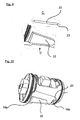
- Fig. 3 is a perspective view of the elastic bushing 1, but without the outer sleeve 7 is shown. There are clearly the inner part 2, the upper working chamber 5 with the upper stop 14, as well as the front side circumferential annular regions 16 and 17 with the sealing lips for the outer sleeve 7 recognizable.
- the elastomer layer 9 can be seen, in which the sub-channels 10a, 10b and the transition contour chamber 11 are formed.
- the sub-channels 10a and 10b each extend laterally adjacent to the working chambers 5 and 6.
- the sub-channel 10b is connected to the upper working chamber 5 via a lateral chamber outlet opening 18b. From there, the sub-channel 10b runs past the upper working chamber 5 and the lower working chamber 6 in the circumferential direction and opens at the junction 19b into the transition contour chamber 11.
- the other subchannel 10a begins at a chamber outlet opening 18a (not visible in FIG. 3) of the lower working chamber 6 and runs in the opposite circumferential direction as far as the junction 19a into the transitional chamber 11 next to the lower working chamber 6 and the upper working chamber 5 Transitional contour chamber 11, the flow connection between the sub-channels 10a, 10b and their junctions 19a, 19b made.
- FIGS. 3 to 10 show different embodiments of the transition contour chamber and the flow-influencing contours contained therein: In all the embodiments of a transition contour chamber 11 shown, this is formed at least partially as a cylindrical section with a vertically projecting section surface.
- the upper limit 20 of the current-carrying contour has in all embodiments a flow-optimized curve between the junctions 19a and 19b.
- longitudinally aligned longitudinal laminations 21 are formed below and laterally to the junction 19a in the lower region of the transitional contour chamber 11, the upper connecting line of which corresponds to a lower boundary of the flow guidance contour approximately parallel to the upper boundary 20.
- the longitudinal lamellae 21 are set somewhat obliquely in the flow direction from the junction 19b to the junction 19a.
- Fig. 7 it is indicated that, depending on the circumstances, other flow-conducting elevations and / or depressions can be attached in order to optimize the flow path.
- Fig. 8 are also in cross section specified different structures that can be used as needed and optimization.
- a flow-conducting contour element is subsequently attached in a form-fitting manner in the transition contour chamber 11 after removal from the mold. As can be seen from FIG. 9, the latter is positively inserted into a dovetail guide 23 in the removal direction.
Landscapes
- Engineering & Computer Science (AREA)
- General Engineering & Computer Science (AREA)
- Mechanical Engineering (AREA)
- Combined Devices Of Dampers And Springs (AREA)
Abstract
Die Erfindung betrifft eine elastische Lagerbuchse mit hydraulischer Dämpfung mit einem Innenteil (2) zur Verbindung mit einem ersten zu lagernden Bauteil und mit einem Außenrohr (3). Ein Elastomerkörper (4) ist zwischen dem Innenteil (2) und dem Außenrohr (3) angebracht, der zwei, radial gegenüberliegende, mit hydraulischer Flüssigkeit gefüllte Arbeitskammern (5, 6) aufweist, die durch zugeordnete Aussparungen im Außenrohr (3) und im Elastomerkörper (4), sowie durch eine flüssigkeitsdicht abschließende Außenhülse (7) gebildet sind. Ein Strömungskanal (10a, 10b, 11) ist zur Strömungsverbindung der zwei Arbeitskammern (5, 6) vorgesehen. Erfindungsgemäß ist auf dem Außenrohr (3) radial außen eine Elastomerschicht (9) aufgebracht, in der der Strömungskanal (10a, 10b) mit seinem Kanalboden und den Kanalseitenwänden sowie eine Übergangskonturkammer (11) eingeformt ist, wobei der Strömungskanal (10a, 10b) und die Übergangskonturkammer (11) radial außen von der Außenhülse (7) flüssigkeitsdicht begrenzt sind. Der Strömungskanal besteht aus zwei Teilkanälen (10a, 10b), von denen jeweils ein Teilkanal (10a, 10b) seitlich neben den Arbeitskammern (5, 6) in einer Querebene verläuft, dergestalt dass der erste Teilkanal (10b) mit der ersten Arbeitskammer (5) über eine erste seitliche Kammerausgangsöffnung (18b) verbunden ist, neben der ersten Arbeitskammer (5) und der zweiten Arbeitskammer (6) in Umfangsrichtung vorbeiläuft und in die Übergangskonturkammer (11) einmündet, und dass der zweite Teilkanal (10a) entsprechend axial gegenüberliegend ausgebildet ist.

Description
Die Erfindung betrifft eine elastische Lagerbuchse mit hydraulischer Dämpfung insbesondere für Lagerungen in einem Kraftfahrzeug oder als Maschinenlagerung nach dem Oberbegriff des Anspruchs 1.The invention relates to an elastic bushing with hydraulic damping, in particular for bearings in a motor vehicle or as a machine bearing according to the preamble of
Bekannte gattungsgemäße elastische Lagerbuchsen mit hydraulischer Dämpfung (
Bei einer solchen elastischen Lagerbuchse mit hydraulischer Dämpfung wird bei radialer oszilierender Ein- und Ausfederung eine Änderung des Volumens mit einer Änderung des Drucks in den Arbeitskammern erzeugt, die von der Einfederung und der Beulfähigkeit oder sog. Volumensteifigkeit der Kammerbegrenzungen abhängig ist. Durch eine solche Volumenänderung wird Flüssigkeit von der einen Arbeitskammer durch den Strömungskanal in die andere Arbeitskammer und zurück verdrängt. Das gewünschte Dämpfungs- oder Tilgungsverhalten ergibt sich durch die Eigenschwingung der Flüssigkeitsmasse im Strömungskanal, welche gegen die Volumensteifigkeit schwingt. Das Dämpfungsverhalten ist dabei abhängig von Eintritts-, Umlenk- und Reibungsverlusten im Strömungskanal. Erzielbar sind mechanische Verlustwinkel bis zu 60°, je nach Amplitude im Frequenzbereich von im allgemeinen größer/gleich 5 Hz. Hohe Verlustwinkel bei gewünscht niedrigen Frequenzen sind bauartbedingt regelmäßig dann erreichbar, wenn die schwingende Flüssigkeitsmasse im Strömungskanal möglichst groß ist, was durch einen möglichst langen Strömungskanal zu erreichen ist.In such an elastic bushing with hydraulic damping a change in the volume is generated with a change in the pressure in the working chambers with radial oszilierender rebound and rebound, which is dependent on the deflection and buckling or so-called. Volume stiffness of the chamber boundaries. By such a change in volume, liquid is displaced from one working chamber through the flow channel into the other working chamber and back. The desired damping or repayment behavior results from the natural vibration of the liquid mass in the flow channel, which oscillates against the volume stiffness. The damping behavior is dependent on entry, deflection and friction losses in the flow channel. Achievable are mechanical loss angles up to 60 °, depending on the amplitude in the frequency range of generally greater than / equal to 5 Hz. High loss angle at desired low frequencies are due to the design regularly reachable when the oscillating fluid mass in the flow channel is as large as possible, which is as long as possible Flow channel is reached.
Bei den bekannten Lagern wird dies durch eine zum Teil mehrfach umlaufende Strömungskanalführung an der Buchsenmantelfläche erreicht. Diese Kanalführung erfolgt in zusätzlichen Bauteilen wie Kanalträgern oder Einsätzen. Dies führt zu einem komplexen Lageraufbau mit relativ hohen Herstellkosten.In the known bearings this is achieved by a partially multi-circumferential flow channel guide on the bushing surface area. This ducting takes place in additional components such as channel girders or inserts. This leads to a complex bearing structure with relatively high production costs.
Aufgabe der Erfindung ist es demgegenüber, eine gattungsgemäße elastische Lagerbuchse mit hydraulischer Dämpfung so weiterzubilden, dass sie bei einfachem Aufbau und guter Funktion kostengünstig herstellbar ist und einen langen Strömungskanal aufweist.Object of the invention is in contrast to develop a generic elastic bushing with hydraulic damping so that it is inexpensive to produce with a simple structure and good function and has a long flow channel.
Diese Aufgabe wird mit den Merkmalen des Anspruchs 1 gelöst.This object is achieved with the features of
Gemäß Anspruch 1 ist auf dem Außenrohr radial außen eine Elastomerschicht aufgebracht, in der der Strömungskanal mit seinem Kanalboden und den Kanalseitenwänden sowie eine Übergangskonturkammer eingeformt sind, wobei der Strömungskanal und die Übergangskonturkammer radial außen von der Außenhülse flüssigkeitsdicht begrenzt sind.According to
Der Strömungskanal besteht aus zwei Kanalteilen, von denen jeweils ein Kanalteil seitlich neben den Arbeitskammern in einer Querebene verläuft dergestalt, dass der erste Teilkanal mit der ersten Arbeitskammer über eine erste seitliche Kammerausgangsöffnung verbunden ist, neben der ersten Arbeitskammer und der zweiten Arbeitskammer in Umfangsrichtung vorbeiläuft und in die Übergangskonturkammer einmündet. Entsprechend ist der zweite Teilkanal mit der zweiten Arbeitskammer über eine zweite seitliche Kammerausgangsöffnung verbunden und läuft neben der zweiten Arbeitskammer und der ersten Arbeitskammer in der entgegengesetzten Umfangsrichtung vorbei, wonach er ebenfalls in die Übergangskonturkammer einmündet. Über diese Übergangskonturkammer ist die Strömungsverbindung der axial gegenüberliegenden Teilkanäle hergestellt.The flow channel consists of two channel parts, of which in each case a channel part extends laterally next to the working chambers in a transverse plane in such a way, the first subchannel is connected to the first working chamber via a first lateral chamber outlet opening, passes in the circumferential direction next to the first working chamber and the second working chamber and opens into the transitional contour chamber. Correspondingly, the second subchannel is connected to the second working chamber via a second lateral chamber outlet opening and runs alongside the second working chamber and the first working chamber in the opposite circumferential direction, after which it also opens into the transitional contour chamber. About this transition contour chamber, the flow connection of the axially opposite sub-channels is made.
Die erfindungsgemäße elastische Buchse enthält einen gewünscht langen Strömungskanal und ist einfach aufgebaut, sowie einfach und kostengünstig zu fertigen, da keine zusätzlichen aufwendigen Bauteile, wie z. B. Kanalträger erforderlich sind. Das Lagerteil bestehend aus dem Innenteil, dem Außenrohr und dem Elastomermaterial ist bei der Fertigung einfach in vertikaler Richtung aus einer horizontal geteilten Form zu entformen, da beim Strömungskanalverlauf keine Hinterschneidungen vorliegen und auch Strömungsführungskonturen in der Übergangskonturkammer einfach entformbar gestaltet werden können, wobei zusätzlich eine die Strömung günstig beeinflussende Geometrie einformbar ist.The elastic bushing according to the invention contains a desired long flow channel and is simple in construction, and easy and inexpensive to manufacture, since no additional complex components, such. B. channel support are required. The bearing part consisting of the inner part, the outer tube and the elastomer material is easy to remove in the vertical direction from a horizontally split shape during production, since there are no undercuts in the flow channel course and flow guidance contours in the transition contour chamber can be easily demoulded, with an additional Flow favorable influencing geometry is einformbar.
Gemäß einer vorteilhaften Weiterbildung nach Anspruch 2 hat die Übergangskonturkammer einen größeren Querschnitt als die Teilkanäle, so dass diese gegenüber den Teilkanälen eine Erweiterung darstellt. Dadurch wird vorteilhaft die schwingende Flüssigkeitsmasse zur Erzielung eines geeigneten Dämpfungsverhaltens weiter vergrößert. Zudem kann in der Übergangskontur eine Strömungsführungskontur zwischen den einmündenden Teilkanälen ausgebildet werden, mit der die Strömung der Flüssigkeit im Sinne eines geeigneten Dämpfungsverhaltens positiv beeinflussbar ist.According to an advantageous development according to
Für eine einfache Entformung bei der Herstellung ist es zweckmäßig, die Übergangskonturkammer zumindest teilweise als Zylinderabschnitt auszubilden, wobei die Abschnittfläche in der Entformrichtung liegt.For a simple demolding in the production, it is expedient to form the transition contour chamber at least partially as a cylindrical portion, wherein the portion surface is located in the Entformrichtung.
Bei einem bevorzugten Einbau nach Anspruch 4, beispielsweise als Aggregatlager, wird die Lagerbuchse in ein Aufnahmeauge des zweiten zu lagernden Bauteils, beispielsweise eines Fahrerhauses eines Lkw, mit etwa horizontaler Buchsenachse und vertikal übereinanderliegenden Arbeitskammern eingepresst. Eine so eingebaute Lagerbuchse ist dann für eine gedämpfte elastische Abstützung vertikaler Belastungen geeignet.In a preferred installation according to
Vorteilhaft kann die obere Begrenzung (bezogen auf die vorstehend genannte Einbaulage) der Stromführungskontur in der Übergangskonturkammer einen strömungsoptimierten Kurvenverlauf zwischen der Einmündung des ersten Teilkanals und des zweiten Teilkanals aufweisen. Dabei ist die Entformbarkeit gewährleistet.Advantageously, the upper limit (based on the above-mentioned mounting position) of the current-carrying contour in the transition contour chamber have a flow-optimized curve between the junction of the first sub-channel and the second sub-channel. The demolding is guaranteed.
Zudem können im unteren Bereich (bezogen auf die vorstehend genannte Einbaulage) der Übergangskonturkammer etwa unter der Einmündung des zweiten Teilkanals vertikal ausgerichtete Längslamellen eingeformt sein, deren obere Verbindungslinie einer unteren Begrenzung der Stromführungskontur gegebenenfalls in Verbindung mit dem vorstehend genannten strömungsoptimierten Kurvenverlauf der oberen Begrenzung entspricht. Durch Verwendung von Längslamellen ist damit die Nachbildung eines geeigneten Stromführungskanals möglich, wobei durch die vertikale Ausrichtung der Längslamellen die Entformbarkeit gewährleistet ist. Gegebenenfalls können die Längslamellen auch etwas schräg gestellt sein, insbesondere in Strömungsrichtung, wodurch ebenfalls noch die Entformbarkeit gegeben ist.In addition, in the lower region (based on the above-mentioned installation position) of the transitional contour chamber may be formed approximately below the junction of the second sub-channel vertically aligned longitudinal slats whose upper connecting line corresponds to a lower limit of the current-carrying contour optionally in conjunction with the flow-optimized curve above the upper limit. The use of longitudinal lamellae makes it possible to replicate a suitable current-carrying channel, the mold being able to be removed from mold by the vertical orientation of the longitudinal lamellae. Optionally, the longitudinal lamellae can also be set slightly obliquely, in particular in the flow direction, as a result of which demoldability is likewise still present.
Alternativ oder zusätzlich können in der Übergangskonturkammer ein oder mehrere strömungsleitende Konturelemente nachträglich nach der Entformung formschlüssig und/oder kraftschlüssig angebracht werden. Damit ist eine weitere Anpassung und Abstimmung an konkrete Gegebenheiten möglich.Alternatively or additionally, in the transition contour chamber one or more flow-conducting contour elements can be subsequently attached in a form-fitting and / or force-fitting manner after demoulding. This allows further adaptation and coordination to specific circumstances.
Als weitere Maßnahme zur Beeinflussung der Strömung können nach Anspruch 8 im unteren Bereich der Übergangskonturkammer (bezogen auf die oben genannte Einbaulage) etwa unter der Einmündung des zweiten Teilkanals Vertiefungen eingeformt sein, um hier ein "Totwassergebiet" zu erzeugen oder zu verstärken. Für die Vertiefungen können unterschiedliche Geometrien gewählt werden.As a further measure to influence the flow can be formed in accordance with
In einer weiteren Ausgestaltung nach Anspruch 9 sind am Innenteil mit Elastomermaterial überzogene Anschläge angeformt, die radial in die Arbeitskammern unter Berücksichtigung eines freien Federwegs einragen. Bei starken Ein- oder Ausfederungen kommen diese Anschläge an der Innenseite der Außenhülse zur Anlage und stützen sich darüber im Aufnahmeauge ab.In a further embodiment according to
Für eine gute Tragfunktion ist das Innenteil etwa entsprechend einem Rohr oder einem Konuslager im Querschnitt nach unten konisch verjüngt ausgebildet. Zudem ist das Innenteil aus Kunststoff mit einer zentralen Bohrung zur Aufnahme einer Schwenkachse hergestellt. Ein solches Lager ist u. a. gut geeignet zur Abstützung des Fahrerhauses eines Lkw.For a good support function, the inner part is approximately conically tapered downwards in cross-section corresponding to a pipe or cone bearing. In addition, the inner part is made of plastic with a central bore for receiving a pivot axis. Such a warehouse is u. a. well suited to support the cab of a truck.
Anhand einer Zeichnung wird die Erfindung näher erläutert.Reference to a drawing, the invention is explained in detail.
Es zeigen:
- Fig. 1
- einen Querschnitt durch eine elastische Lagerbuchse mit hydraulischer Dämpfung,
- Fig. 2
- einen entsprechenden Längsschnitt,
- Fig. 3
- eine perspektivische Ansicht der Lagerbuchse,
- Fig. 4 bis 7
- jeweils eine Draufsicht auf eine Übergangskonturkammer mit unterschiedlichen Strömungsleitmaßnahmen,
- Fig. 8
- unterschiedliche Geometrien für Vertiefungen bzw. Lamellenausführungen in der Übergangskonturkammer,
- Fig. 9
- eine Detailansicht eines strömungsleitenden Konturelements, und
- Fig. 10
- eine perspektivische Ansicht einer Lagerbuchse mit dem Konturelement nach Fig. 9.
- Fig. 1
- a cross section through an elastic bushing with hydraulic damping,
- Fig. 2
- a corresponding longitudinal section,
- Fig. 3
- a perspective view of the bearing bush,
- Fig. 4 to 7
- in each case a plan view of a transition contour chamber with different Strömungsleitmaßnahmen,
- Fig. 8
- different geometries for depressions or fin embodiments in the transition contour chamber,
- Fig. 9
- a detailed view of a flow-conducting contour element, and
- Fig. 10
- a perspective view of a bearing bush with the contour element of FIG. 9th
In den Fig. 1 bis 3 ist eine elastische Lagerbuchse 1 dargestellt, die aus einem Innenteil 2, einem Außenrohr 3 und einem Elastomerkörper 4 zwischen dem Innenteil 2 und dem Außenrohr 3 besteht.1 to 3, an
Zudem sind zwei radial gegenüberliegende, mit hydraulischer Flüssigkeit gefüllte Arbeitskammern ausgebildet (obere Arbeitskammer 5 und untere Arbeitskammer 6), die durch zugeordnete Aussparungen im Außenrohr 3 sowie im Elastomerkörper 4 und durch eine flüssigkeitsdicht abschließende Außenhülse 7 hergestellt sind. Wie aus den Fig. 1 und 2 ersichtlich, sind damit die Arbeitskammern 5, 6 bezüglich des Elastomermaterials an den jeweiligen Kammerböden von den beidseitigen stark dimensionierten Elastomerpaketen und in den Seitenbereichen von zur Lagermitte eingezogenen dünnwandigeren Elastomerwänden 8 begrenzt. Bedingt durch die Ausnehmungen am Außenrohr 3 im Bereich der Arbeitskammern 5, 6 sind in Fig. 1 lediglich gegenüberliegende ringförmig umlaufende Seitenabschnitte des Außenrohrs 3 und entsprechen in Fig. 2 nur die eingeformten umlaufenden Ringbereiche des Außenrohrs 3 sichtbar.In addition, two radially opposite, filled with hydraulic fluid working chambers are formed (upper working
Auf dem Außenrohr 3 ist radial außen eine Elastomerschicht 9 aufgebracht, in der ein Strömungskanal 10 mit seinen beiden Teilkanälen 10a, 10b sowie eine Übergangskonturkammer 11 eingeformt sind, wobei die Teilkanäle 10a, 10b und die Übergangskonturkammer 11 radial außen von der Außenhülse 7 flüssigkeitsdicht begrenzt sind.On the
Am Innenteil 2 sind in einem axial mittleren Bereich gegenüberliegende, mit Elastomermaterial 13 überzogene Anschläge 14 angeformt, die jeweils radial in die Arbeitskammern 5, 6 einragen. Das Innenteil 2 ist im Querschnitt nach unten konisch verjüngt ausgebildet. Es ist vorzugsweise aus Kunststoff hergestellt mit einer zentralen Bohrung 15 zur Aufnahme einer metallischen Schwenkachse.On the
In Fig. 3 ist eine perspektivische Ansicht der elastischen Lagerbuchse 1, jedoch ohne die Außenhülse 7 gezeigt. Es sind hier deutlich das Innenteil 2, die obere Arbeitskammer 5 mit dem oberen Anschlag 14, sowie die stirnseitig umlaufenden Ringbereiche 16 und 17 mit den Dichtlippen für die Außenhülse 7 erkennbar. Zudem ist die Elastomerschicht 9 zu ersehen, in die die Teilkanäle 10a, 10b und die Übergangskonturkammer 11 eingeformt sind.In Fig. 3 is a perspective view of the
Die Teilkanäle 10a und 10b verlaufen jeweils seitlich neben den Arbeitskammern 5 und 6. Dabei ist der Teilkanal 10b mit der oberen Arbeitskammer 5 über eine seitliche Kammerausgangsöffnung 18b verbunden. Von dort läuft der Teilkanal 10b an der oberen Arbeitskammer 5 und der unteren Arbeitskammer 6 in Umfangsrichtung vorbei und mündet an der Einmündung 19b in die Übergangskonturkammer 11.The sub-channels 10a and 10b each extend laterally adjacent to the working
Entsprechend beginnt der andere Teilkanal 10a an einer (in Fig. 3 nicht zu ersehenden) Kammerausgangsöffnung 18a der unteren Arbeitskammer 6 und verläuft neben der unteren Arbeitskammer 6 und der oberen Arbeitskammer 5 in der entgegengesetzten Umfangsrichtung bis zur Einmündung 19a in die Überganskonturkammer 11. In der Übergangskonturkammer 11 ist die Strömungsverbindung zwischen den Teilkanälen 10a, 10b bzw. deren Einmündungen 19a, 19b hergestellt.Correspondingly, the
In den Fig. 3 bis 10 sind unterschiedliche Ausbildungen der Übergangskonturkammer und der darin enthaltene strömungsbeeinflussende Konturen gezeigt: In allen gezeigten Ausführungen einer Übergangskonturkammer 11 ist diese zumindest teilweise als Zylinderabschnitt ausgebildet mit einer vertikalstehenden Abschnittsfläche. Die obere Begrenzung 20 der Stromführungskontur hat in allen Ausführungsformen einen strömungsoptimierten Kurvenverlauf zwischen den Einmündungen 19a und 19b.FIGS. 3 to 10 show different embodiments of the transition contour chamber and the flow-influencing contours contained therein: In all the embodiments of a
In der Ausführungsform nach Fig. 4 sind keine weiteren strömungsführenden Maßnahmen mehr vorgesehen.In the embodiment according to FIG. 4, no further flow-carrying measures are provided.
In den Ausführungen nach Fig. 3 und Fig. 5 sind dagegen im unteren Bereich der Übergangskonturkammer 11 unterhalb und seitlich zur Einmündung 19a vertikal ausgerichtete Längslamellen 21 angeformt, deren obere Verbindungslinie einer unteren Begrenzung der Stromführungskontur etwa parallel mitlaufend mit der oberen Begrenzung 20 entspricht. In der Ausführungsform nach Fig. 6 sind die Längslamellen 21 etwas schräg in Strömungsrichtung von der Einmündung 19b zur Einmündung 19a angestellt.In the embodiments according to FIGS. 3 and 5, however, longitudinally aligned
In Fig. 7 ist angedeutet, dass je nach den Gegebenheiten auch andere strömungsleitende Erhebungen und/oder Vertiefungen angebracht werden können, um den Strömungsverlauf zu optimieren. In Fig. 8 sind zudem im Querschnitt unterschiedliche Strukturen angegeben, die je nach Bedarf und Optimierung eingesetzt werden können.In Fig. 7 it is indicated that, depending on the circumstances, other flow-conducting elevations and / or depressions can be attached in order to optimize the flow path. In Fig. 8 are also in cross section specified different structures that can be used as needed and optimization.
In der Ausführung gemäß Fig. 9 und 10 ist nachträglich nach der Entformung ein strömungsleitendes Konturelement formschlüssig in der Übergangskonturkammer 11 angebracht. Wie aus Fig. 9 ersichtlich ist dieses formschlüssig in Entformungsrichtung in eine Schwalbenschwanzführung 23 eingesteckt.In the embodiment according to FIGS. 9 and 10, a flow-conducting contour element is subsequently attached in a form-fitting manner in the
Claims (10)
mit einem Innenteil (2) zur Verbindung mit einem ersten zu lagernden Bauteil und einem Außenrohr (3),
mit einem Elastomerkörper (4) zwischen dem Innenteil (2) und dem Außenrohr (3),
mit zwei, radial gegenüberliegenden, mit hydraulischer Flüssigkeit gefüllten Arbeitskammern (5, 6), die durch zugeordnete Aussparungen im Außenrohr (3) und im Elastomerkörper (4) sowie durch eine flüssigkeitsdicht abschließende Außenhülse (7) gebildet sind, und
mit einem Strömungskanal (10a, 10b, 11) zur Strömungsverbindung der zwei Arbeitskammern (5, 6),
dadurch gekennzeichnet,
dass auf dem Außenrohr (3) radial außen eine Elastomerschicht (9) aufgebracht ist, in der der Strömungskanal (10a, 10b) mit seinem Kanalboden und den Kanalseitenwänden sowie eine Übergangskonturkammer (11) eingeformt ist, wobei der Strömungskanal (10a, 10b) und die Übergangskonturkammer (11) radial außen von der Außenhülse (7) flüssigkeitsdicht begrenzt sind, und
dass der Strömungskanal aus zwei Teilkanälen (10a, 10b) besteht, von denen jeweils ein Teilkanal (10a, 10b) seitlich neben den Arbeitskammern (5, 6) in einer Querebene verläuft, dergestalt
dass der erste Teilkanal (10b) mit der ersten Arbeitskammer (5) über eine erste seitliche Kammerausgangsöffnung (18b) verbunden ist, neben der ersten Arbeitskammer (5) und der zweiten Arbeitskammer (6) in Umfangsrichtung vorbeiläuft und in die Übergangskonturkammer (11) einmündet, und
dass der zweite Teilkanal (10a) entsprechend mit der zweiten Arbeitskammer (6) über eine zweite seitliche Kammerausgangsöffnung (19a) verbunden ist, neben der zweiten Arbeitskammer (6) und der ersten Arbeitskammer (5) in der entgegengesetzten Umfangsrichtung vorbeiläuft und ebenfalls in die Übergangskonturkammer (11) einmündet, über die in Buchsenlängsrichtung eine Strömungsverbindung zwischen dem ersten Teilkanal (10b) und dem zweiten Teilkanal (10a) hergestellt ist.Elastic bushing with hydraulic damping
with an inner part (2) for connection to a first component to be supported and an outer tube (3),
with an elastomeric body (4) between the inner part (2) and the outer tube (3),
with two, radially opposite, filled with hydraulic fluid working chambers (5, 6), which are formed by associated recesses in the outer tube (3) and in the elastomer body (4) and by a liquid-tight final outer sleeve (7), and
with a flow channel (10a, 10b, 11) for the flow connection of the two working chambers (5, 6),
characterized,
that on the outer tube (3) radially on the outside, an elastomer layer (9) is applied, in which the flow channel (10a, 10b) is formed with its channel bottom and channel side walls, and a transition contour chamber (11), wherein the flow channel (10a, 10b) and the transition contour chamber (11) are bounded liquid-tight radially outside of the outer sleeve (7), and
that the flow passage consists of two sub-channels (10a, 10b), each having one sub-channel (10a, 10b) laterally next to the working chambers (5, 6) extends in a transverse plane, in such a way
in that the first sub-channel (10b) is connected to the first working chamber (5) via a first lateral chamber outlet opening (18b), passes in the circumferential direction next to the first working chamber (5) and the second working chamber (6) and opens into the transitional contour chamber (11) , and
in that the second sub-passage (10a) is correspondingly connected to the second working chamber (6) via a second lateral chamber exit port (19a), alongside the second working chamber (6) and the first working chamber (5) in the opposite circumferential direction and also into the transitional contour chamber (11), via which a flow connection between the first part-channel (10b) and the second part-channel (10a) is established in the longitudinal direction of the receptacle.
dass die Übergangskonturkammer (11) eine Strömungsführungskontur (20; 21; 22) zwischen den einmündenden Teilkanälen (10a, 10b) aufweist.Elastic bushing according to claim 1, characterized in that the transition contour chamber (11) has a larger cross-section than the sub-channels (10a, 10b) and with respect to this represents an extension, and
the transition contour chamber (11) has a flow guidance contour (20; 21; 22) between the opening partial passages (10a, 10b).
dass das Innenteil (2) aus Kunststoff mit einer zentralen Bohrung (15) zur Aufnahme einer Schwenkachse hergestellt ist.Elastic bushing according to one of claims 1 to 9, characterized in that the inner part (2) is tubular or conically tapered in cross-section downwards, and
in that the inner part (2) is made of plastic with a central bore (15) for receiving a pivot axis.
Applications Claiming Priority (1)
| Application Number | Priority Date | Filing Date | Title |
|---|---|---|---|
| DE102006047446A DE102006047446A1 (en) | 2006-10-07 | 2006-10-07 | Elastic bushing with hydraulic damping |
Publications (3)
| Publication Number | Publication Date |
|---|---|
| EP1908986A2 true EP1908986A2 (en) | 2008-04-09 |
| EP1908986A3 EP1908986A3 (en) | 2010-07-07 |
| EP1908986B1 EP1908986B1 (en) | 2011-09-28 |
Family
ID=38984224
Family Applications (1)
| Application Number | Title | Priority Date | Filing Date |
|---|---|---|---|
| EP07019118A Not-in-force EP1908986B1 (en) | 2006-10-07 | 2007-09-28 | Elastic bearing sleeve with hydraulic damping |
Country Status (3)
| Country | Link |
|---|---|
| EP (1) | EP1908986B1 (en) |
| AT (1) | ATE526515T1 (en) |
| DE (1) | DE102006047446A1 (en) |
Family Cites Families (6)
| Publication number | Priority date | Publication date | Assignee | Title |
|---|---|---|---|---|
| JP2583212B2 (en) * | 1985-05-27 | 1997-02-19 | 日産自動車株式会社 | Vibration damping device |
| FR2669091B1 (en) * | 1990-11-13 | 1995-02-17 | Hutchinson | IMPROVEMENTS TO HYDRAULIC ANTI-VIBRATION SLEEVES. |
| JPH0642577A (en) * | 1992-07-23 | 1994-02-15 | Marugo Rubber Kogyo Kk | Liquid mount device |
| JPH06346943A (en) * | 1993-06-10 | 1994-12-20 | Kurashiki Kako Co Ltd | Liquid sealed type vibration control device |
| DE4320643C2 (en) * | 1993-06-22 | 1997-02-06 | Hubert Dipl Ing Bruehl | Hydraulically damping bush bearing |
| DE4332367C2 (en) * | 1993-09-23 | 1995-10-12 | Lemfoerder Metallwaren Ag | Sleeve rubber spring for bearings in a motor vehicle |
-
2006
- 2006-10-07 DE DE102006047446A patent/DE102006047446A1/en not_active Withdrawn
-
2007
- 2007-09-28 AT AT07019118T patent/ATE526515T1/en active
- 2007-09-28 EP EP07019118A patent/EP1908986B1/en not_active Not-in-force
Also Published As
| Publication number | Publication date |
|---|---|
| DE102006047446A1 (en) | 2008-04-10 |
| EP1908986B1 (en) | 2011-09-28 |
| ATE526515T1 (en) | 2011-10-15 |
| EP1908986A3 (en) | 2010-07-07 |
Similar Documents
| Publication | Publication Date | Title |
|---|---|---|
| EP1162338B1 (en) | Shock absorbing device, especially for cabinet doors or drawers | |
| DE102005046407B4 (en) | engine cover | |
| DE3039801C2 (en) | ||
| DE10347533B4 (en) | Linear guide device and method of assembling same | |
| EP3737875B1 (en) | Hydraulic bearing bush | |
| DE19529168A1 (en) | Hydraulic door closer and method of making the same | |
| EP1611367A1 (en) | Hydraulically damping rubber bush bearing for vertical mounting | |
| DE202004001679U1 (en) | Clamp or guide rail with installation channel | |
| DE10135931A1 (en) | motorcycle frame | |
| EP1908987A2 (en) | Elastic bearing sleeve with hydraulic damping | |
| EP1908986B1 (en) | Elastic bearing sleeve with hydraulic damping | |
| DE102005009348B4 (en) | Adaptable sliding bearing for telescopic crane jib | |
| DE102004014328B4 (en) | Hydraulically damping rubber mount | |
| DE102005054852A1 (en) | Hydraulic bearing and method for producing a hydraulic bearing | |
| DE102013006196B4 (en) | Suction pipe for gas of an internal combustion engine with a flap unit | |
| EP1908988B1 (en) | Exterior sleeve for an elastic bush with hydraulic damping | |
| EP2058551B1 (en) | Elastic bearing sleeve with hydraulic dampening | |
| DE102005003552B4 (en) | Crosshead engine | |
| DE102005004997A1 (en) | Pedal, for motor vehicle, has pedal lever with corrugations that are arranged in facing walls at outer surface of lever, where walls lie parallel in deflection direction of lever that is supported in area of its end around rotation axis | |
| DE19936956B4 (en) | Process for producing a plastic molding | |
| DE102015211365A1 (en) | Slide rail with hydrostatic bearing | |
| EP2058550B1 (en) | Elastic bearing sleeve with hydraulic dampening | |
| DE102005054851A1 (en) | Hydraulic bearing and method for producing a hydraulic bearing | |
| DE10314242A1 (en) | servo cylinder | |
| DE102007053111A1 (en) | Rubber bushing with hydraulic damping |
Legal Events
| Date | Code | Title | Description |
|---|---|---|---|
| PUAI | Public reference made under article 153(3) epc to a published international application that has entered the european phase |
Free format text: ORIGINAL CODE: 0009012 |
|
| AK | Designated contracting states |
Kind code of ref document: A2 Designated state(s): AT BE BG CH CY CZ DE DK EE ES FI FR GB GR HU IE IS IT LI LT LU LV MC MT NL PL PT RO SE SI SK TR |
|
| AX | Request for extension of the european patent |
Extension state: AL BA HR MK RS |
|
| PUAL | Search report despatched |
Free format text: ORIGINAL CODE: 0009013 |
|
| AK | Designated contracting states |
Kind code of ref document: A3 Designated state(s): AT BE BG CH CY CZ DE DK EE ES FI FR GB GR HU IE IS IT LI LT LU LV MC MT NL PL PT RO SE SI SK TR |
|
| AX | Request for extension of the european patent |
Extension state: AL BA HR MK RS |
|
| 17P | Request for examination filed |
Effective date: 20110103 |
|
| AKX | Designation fees paid |
Designated state(s): AT BE BG CH CY CZ DE DK EE ES FI FR GB GR HU IE IS IT LI LT LU LV MC MT NL PL PT RO SE SI SK TR |
|
| GRAP | Despatch of communication of intention to grant a patent |
Free format text: ORIGINAL CODE: EPIDOSNIGR1 |
|
| RIC1 | Information provided on ipc code assigned before grant |
Ipc: F16F 13/14 20060101AFI20110307BHEP |
|
| GRAS | Grant fee paid |
Free format text: ORIGINAL CODE: EPIDOSNIGR3 |
|
| GRAA | (expected) grant |
Free format text: ORIGINAL CODE: 0009210 |
|
| AK | Designated contracting states |
Kind code of ref document: B1 Designated state(s): AT BE BG CH CY CZ DE DK EE ES FI FR GB GR HU IE IS IT LI LT LU LV MC MT NL PL PT RO SE SI SK TR |
|
| REG | Reference to a national code |
Ref country code: GB Ref legal event code: FG4D Free format text: NOT ENGLISH |
|
| REG | Reference to a national code |
Ref country code: CH Ref legal event code: EP |
|
| REG | Reference to a national code |
Ref country code: IE Ref legal event code: FG4D |
|
| REG | Reference to a national code |
Ref country code: DE Ref legal event code: R096 Ref document number: 502007008243 Country of ref document: DE Effective date: 20111215 |
|
| REG | Reference to a national code |
Ref country code: NL Ref legal event code: VDEP Effective date: 20110928 |
|
| PG25 | Lapsed in a contracting state [announced via postgrant information from national office to epo] |
Ref country code: SE Free format text: LAPSE BECAUSE OF FAILURE TO SUBMIT A TRANSLATION OF THE DESCRIPTION OR TO PAY THE FEE WITHIN THE PRESCRIBED TIME-LIMIT Effective date: 20110928 Ref country code: FI Free format text: LAPSE BECAUSE OF FAILURE TO SUBMIT A TRANSLATION OF THE DESCRIPTION OR TO PAY THE FEE WITHIN THE PRESCRIBED TIME-LIMIT Effective date: 20110928 Ref country code: LT Free format text: LAPSE BECAUSE OF FAILURE TO SUBMIT A TRANSLATION OF THE DESCRIPTION OR TO PAY THE FEE WITHIN THE PRESCRIBED TIME-LIMIT Effective date: 20110928 |
|
| LTIE | Lt: invalidation of european patent or patent extension |
Effective date: 20110928 |
|
| PG25 | Lapsed in a contracting state [announced via postgrant information from national office to epo] |
Ref country code: CY Free format text: LAPSE BECAUSE OF FAILURE TO SUBMIT A TRANSLATION OF THE DESCRIPTION OR TO PAY THE FEE WITHIN THE PRESCRIBED TIME-LIMIT Effective date: 20110928 Ref country code: LV Free format text: LAPSE BECAUSE OF FAILURE TO SUBMIT A TRANSLATION OF THE DESCRIPTION OR TO PAY THE FEE WITHIN THE PRESCRIBED TIME-LIMIT Effective date: 20110928 Ref country code: SI Free format text: LAPSE BECAUSE OF FAILURE TO SUBMIT A TRANSLATION OF THE DESCRIPTION OR TO PAY THE FEE WITHIN THE PRESCRIBED TIME-LIMIT Effective date: 20110928 Ref country code: GR Free format text: LAPSE BECAUSE OF FAILURE TO SUBMIT A TRANSLATION OF THE DESCRIPTION OR TO PAY THE FEE WITHIN THE PRESCRIBED TIME-LIMIT Effective date: 20111229 |
|
| BERE | Be: lapsed |
Owner name: JORN G.M.B.H. Effective date: 20110930 |
|
| REG | Reference to a national code |
Ref country code: IE Ref legal event code: FD4D |
|
| PG25 | Lapsed in a contracting state [announced via postgrant information from national office to epo] |
Ref country code: SK Free format text: LAPSE BECAUSE OF FAILURE TO SUBMIT A TRANSLATION OF THE DESCRIPTION OR TO PAY THE FEE WITHIN THE PRESCRIBED TIME-LIMIT Effective date: 20110928 Ref country code: MC Free format text: LAPSE BECAUSE OF NON-PAYMENT OF DUE FEES Effective date: 20110930 Ref country code: IS Free format text: LAPSE BECAUSE OF FAILURE TO SUBMIT A TRANSLATION OF THE DESCRIPTION OR TO PAY THE FEE WITHIN THE PRESCRIBED TIME-LIMIT Effective date: 20120128 Ref country code: CZ Free format text: LAPSE BECAUSE OF FAILURE TO SUBMIT A TRANSLATION OF THE DESCRIPTION OR TO PAY THE FEE WITHIN THE PRESCRIBED TIME-LIMIT Effective date: 20110928 |
|
| PGFP | Annual fee paid to national office [announced via postgrant information from national office to epo] |
Ref country code: FR Payment date: 20120319 Year of fee payment: 5 |
|
| REG | Reference to a national code |
Ref country code: CH Ref legal event code: PL |
|
| PG25 | Lapsed in a contracting state [announced via postgrant information from national office to epo] |
Ref country code: PT Free format text: LAPSE BECAUSE OF FAILURE TO SUBMIT A TRANSLATION OF THE DESCRIPTION OR TO PAY THE FEE WITHIN THE PRESCRIBED TIME-LIMIT Effective date: 20120130 Ref country code: NL Free format text: LAPSE BECAUSE OF FAILURE TO SUBMIT A TRANSLATION OF THE DESCRIPTION OR TO PAY THE FEE WITHIN THE PRESCRIBED TIME-LIMIT Effective date: 20110928 Ref country code: RO Free format text: LAPSE BECAUSE OF FAILURE TO SUBMIT A TRANSLATION OF THE DESCRIPTION OR TO PAY THE FEE WITHIN THE PRESCRIBED TIME-LIMIT Effective date: 20110928 Ref country code: EE Free format text: LAPSE BECAUSE OF FAILURE TO SUBMIT A TRANSLATION OF THE DESCRIPTION OR TO PAY THE FEE WITHIN THE PRESCRIBED TIME-LIMIT Effective date: 20110928 |
|
| PG25 | Lapsed in a contracting state [announced via postgrant information from national office to epo] |
Ref country code: BE Free format text: LAPSE BECAUSE OF NON-PAYMENT OF DUE FEES Effective date: 20110930 |
|
| PG25 | Lapsed in a contracting state [announced via postgrant information from national office to epo] |
Ref country code: IE Free format text: LAPSE BECAUSE OF FAILURE TO SUBMIT A TRANSLATION OF THE DESCRIPTION OR TO PAY THE FEE WITHIN THE PRESCRIBED TIME-LIMIT Effective date: 20110928 Ref country code: LI Free format text: LAPSE BECAUSE OF NON-PAYMENT OF DUE FEES Effective date: 20110930 Ref country code: CH Free format text: LAPSE BECAUSE OF NON-PAYMENT OF DUE FEES Effective date: 20110930 Ref country code: DK Free format text: LAPSE BECAUSE OF FAILURE TO SUBMIT A TRANSLATION OF THE DESCRIPTION OR TO PAY THE FEE WITHIN THE PRESCRIBED TIME-LIMIT Effective date: 20110928 |
|
| PLBE | No opposition filed within time limit |
Free format text: ORIGINAL CODE: 0009261 |
|
| STAA | Information on the status of an ep patent application or granted ep patent |
Free format text: STATUS: NO OPPOSITION FILED WITHIN TIME LIMIT |
|
| GBPC | Gb: european patent ceased through non-payment of renewal fee |
Effective date: 20111228 |
|
| PG25 | Lapsed in a contracting state [announced via postgrant information from national office to epo] |
Ref country code: PL Free format text: LAPSE BECAUSE OF FAILURE TO SUBMIT A TRANSLATION OF THE DESCRIPTION OR TO PAY THE FEE WITHIN THE PRESCRIBED TIME-LIMIT Effective date: 20110928 |
|
| 26N | No opposition filed |
Effective date: 20120629 |
|
| REG | Reference to a national code |
Ref country code: DE Ref legal event code: R097 Ref document number: 502007008243 Country of ref document: DE Effective date: 20120629 |
|
| PG25 | Lapsed in a contracting state [announced via postgrant information from national office to epo] |
Ref country code: GB Free format text: LAPSE BECAUSE OF NON-PAYMENT OF DUE FEES Effective date: 20111228 |
|
| PG25 | Lapsed in a contracting state [announced via postgrant information from national office to epo] |
Ref country code: MT Free format text: LAPSE BECAUSE OF FAILURE TO SUBMIT A TRANSLATION OF THE DESCRIPTION OR TO PAY THE FEE WITHIN THE PRESCRIBED TIME-LIMIT Effective date: 20110928 |
|
| PG25 | Lapsed in a contracting state [announced via postgrant information from national office to epo] |
Ref country code: ES Free format text: LAPSE BECAUSE OF FAILURE TO SUBMIT A TRANSLATION OF THE DESCRIPTION OR TO PAY THE FEE WITHIN THE PRESCRIBED TIME-LIMIT Effective date: 20120108 |
|
| PG25 | Lapsed in a contracting state [announced via postgrant information from national office to epo] |
Ref country code: LU Free format text: LAPSE BECAUSE OF NON-PAYMENT OF DUE FEES Effective date: 20110928 |
|
| PG25 | Lapsed in a contracting state [announced via postgrant information from national office to epo] |
Ref country code: BG Free format text: LAPSE BECAUSE OF FAILURE TO SUBMIT A TRANSLATION OF THE DESCRIPTION OR TO PAY THE FEE WITHIN THE PRESCRIBED TIME-LIMIT Effective date: 20111228 |
|
| REG | Reference to a national code |
Ref country code: FR Ref legal event code: ST Effective date: 20130531 |
|
| PG25 | Lapsed in a contracting state [announced via postgrant information from national office to epo] |
Ref country code: IT Free format text: LAPSE BECAUSE OF NON-PAYMENT OF DUE FEES Effective date: 20120928 Ref country code: FR Free format text: LAPSE BECAUSE OF NON-PAYMENT OF DUE FEES Effective date: 20121001 |
|
| PG25 | Lapsed in a contracting state [announced via postgrant information from national office to epo] |
Ref country code: TR Free format text: LAPSE BECAUSE OF FAILURE TO SUBMIT A TRANSLATION OF THE DESCRIPTION OR TO PAY THE FEE WITHIN THE PRESCRIBED TIME-LIMIT Effective date: 20110928 |
|
| PG25 | Lapsed in a contracting state [announced via postgrant information from national office to epo] |
Ref country code: HU Free format text: LAPSE BECAUSE OF FAILURE TO SUBMIT A TRANSLATION OF THE DESCRIPTION OR TO PAY THE FEE WITHIN THE PRESCRIBED TIME-LIMIT Effective date: 20110928 |
|
| PGFP | Annual fee paid to national office [announced via postgrant information from national office to epo] |
Ref country code: DE Payment date: 20130926 Year of fee payment: 7 |
|
| REG | Reference to a national code |
Ref country code: AT Ref legal event code: MM01 Ref document number: 526515 Country of ref document: AT Kind code of ref document: T Effective date: 20120928 |
|
| PG25 | Lapsed in a contracting state [announced via postgrant information from national office to epo] |
Ref country code: AT Free format text: LAPSE BECAUSE OF NON-PAYMENT OF DUE FEES Effective date: 20120928 |
|
| REG | Reference to a national code |
Ref country code: DE Ref legal event code: R119 Ref document number: 502007008243 Country of ref document: DE |
|
| REG | Reference to a national code |
Ref country code: DE Ref legal event code: R119 Ref document number: 502007008243 Country of ref document: DE Effective date: 20150401 |
|
| PG25 | Lapsed in a contracting state [announced via postgrant information from national office to epo] |
Ref country code: DE Free format text: LAPSE BECAUSE OF NON-PAYMENT OF DUE FEES Effective date: 20150401 |