EP1908983B1 - Système de mise à niveau et d'amortissement de vibrations - Google Patents
Système de mise à niveau et d'amortissement de vibrations Download PDFInfo
- Publication number
- EP1908983B1 EP1908983B1 EP06125135A EP06125135A EP1908983B1 EP 1908983 B1 EP1908983 B1 EP 1908983B1 EP 06125135 A EP06125135 A EP 06125135A EP 06125135 A EP06125135 A EP 06125135A EP 1908983 B1 EP1908983 B1 EP 1908983B1
- Authority
- EP
- European Patent Office
- Prior art keywords
- platform
- accordance
- damping
- central
- grub
- Prior art date
- Legal status (The legal status is an assumption and is not a legal conclusion. Google has not performed a legal analysis and makes no representation as to the accuracy of the status listed.)
- Active
Links
Images
Classifications
-
- F—MECHANICAL ENGINEERING; LIGHTING; HEATING; WEAPONS; BLASTING
- F16—ENGINEERING ELEMENTS AND UNITS; GENERAL MEASURES FOR PRODUCING AND MAINTAINING EFFECTIVE FUNCTIONING OF MACHINES OR INSTALLATIONS; THERMAL INSULATION IN GENERAL
- F16F—SPRINGS; SHOCK-ABSORBERS; MEANS FOR DAMPING VIBRATION
- F16F15/00—Suppression of vibrations in systems; Means or arrangements for avoiding or reducing out-of-balance forces, e.g. due to motion
- F16F15/02—Suppression of vibrations of non-rotating, e.g. reciprocating systems; Suppression of vibrations of rotating systems by use of members not moving with the rotating systems
- F16F15/04—Suppression of vibrations of non-rotating, e.g. reciprocating systems; Suppression of vibrations of rotating systems by use of members not moving with the rotating systems using elastic means
- F16F15/06—Suppression of vibrations of non-rotating, e.g. reciprocating systems; Suppression of vibrations of rotating systems by use of members not moving with the rotating systems using elastic means with metal springs
- F16F15/067—Suppression of vibrations of non-rotating, e.g. reciprocating systems; Suppression of vibrations of rotating systems by use of members not moving with the rotating systems using elastic means with metal springs using only wound springs
-
- E—FIXED CONSTRUCTIONS
- E04—BUILDING
- E04F—FINISHING WORK ON BUILDINGS, e.g. STAIRS, FLOORS
- E04F15/00—Flooring
- E04F15/22—Resiliently-mounted floors, e.g. sprung floors
- E04F15/225—Shock absorber members therefor
-
- F—MECHANICAL ENGINEERING; LIGHTING; HEATING; WEAPONS; BLASTING
- F16—ENGINEERING ELEMENTS AND UNITS; GENERAL MEASURES FOR PRODUCING AND MAINTAINING EFFECTIVE FUNCTIONING OF MACHINES OR INSTALLATIONS; THERMAL INSULATION IN GENERAL
- F16F—SPRINGS; SHOCK-ABSORBERS; MEANS FOR DAMPING VIBRATION
- F16F1/00—Springs
- F16F1/02—Springs made of steel or other material having low internal friction; Wound, torsion, leaf, cup, ring or the like springs, the material of the spring not being relevant
- F16F1/04—Wound springs
- F16F1/12—Attachments or mountings
- F16F1/121—Attachments or mountings adjustable, e.g. to modify spring characteristics
-
- F—MECHANICAL ENGINEERING; LIGHTING; HEATING; WEAPONS; BLASTING
- F16—ENGINEERING ELEMENTS AND UNITS; GENERAL MEASURES FOR PRODUCING AND MAINTAINING EFFECTIVE FUNCTIONING OF MACHINES OR INSTALLATIONS; THERMAL INSULATION IN GENERAL
- F16F—SPRINGS; SHOCK-ABSORBERS; MEANS FOR DAMPING VIBRATION
- F16F3/00—Spring units consisting of several springs, e.g. for obtaining a desired spring characteristic
- F16F3/02—Spring units consisting of several springs, e.g. for obtaining a desired spring characteristic with springs made of steel or of other material having low internal friction
- F16F3/04—Spring units consisting of several springs, e.g. for obtaining a desired spring characteristic with springs made of steel or of other material having low internal friction composed only of wound springs
-
- F—MECHANICAL ENGINEERING; LIGHTING; HEATING; WEAPONS; BLASTING
- F16—ENGINEERING ELEMENTS AND UNITS; GENERAL MEASURES FOR PRODUCING AND MAINTAINING EFFECTIVE FUNCTIONING OF MACHINES OR INSTALLATIONS; THERMAL INSULATION IN GENERAL
- F16F—SPRINGS; SHOCK-ABSORBERS; MEANS FOR DAMPING VIBRATION
- F16F3/00—Spring units consisting of several springs, e.g. for obtaining a desired spring characteristic
- F16F3/08—Spring units consisting of several springs, e.g. for obtaining a desired spring characteristic with springs made of a material having high internal friction, e.g. rubber
- F16F3/10—Spring units consisting of several springs, e.g. for obtaining a desired spring characteristic with springs made of a material having high internal friction, e.g. rubber combined with springs made of steel or other material having low internal friction
-
- F—MECHANICAL ENGINEERING; LIGHTING; HEATING; WEAPONS; BLASTING
- F16—ENGINEERING ELEMENTS AND UNITS; GENERAL MEASURES FOR PRODUCING AND MAINTAINING EFFECTIVE FUNCTIONING OF MACHINES OR INSTALLATIONS; THERMAL INSULATION IN GENERAL
- F16F—SPRINGS; SHOCK-ABSORBERS; MEANS FOR DAMPING VIBRATION
- F16F2230/00—Purpose; Design features
- F16F2230/0005—Attachment, e.g. to facilitate mounting onto confer adjustability
Definitions
- the present invention refers to a vibration levelling and damping system as defined in the preamble of claim 1 and known from DE-A-102 05 788 that, besides the damping function, is capable of levelling the height and inclination of the platform where the aforementioned machine is supported. This system additionally provides greater stability in the supporting of the machine.
- One of the possible solutions involves supporting the equipment on damping devices capable of absorbing the vibrations caused, so that these vibrations are eliminated or reduced.
- a damping device of this type is the Vibrabsorber ® system, available commercially, that consists of a kind of sandwich made up of a lower and an upper plate base, inserting a set of springs between both. In the upper part of the base, and in its centre, there is an opening to fix a grub screw with nuts and washers. The leg or support of the machine rests on the lower nut-washer unit. Another way to carry out this connection is to directly support the machine on the upper base.
- damping device used to resolve the previously mentioned disadvantages is the AM series, commercialised by Eddo Comfort Products.
- This damping device consists of a set of insulators in parallel fitted between two plates, the upper plate having a central opening to join a central grub screw. Its most outstanding feature is the lateral shielding that limits the rocking of the insulator when confronting recurrent forces under dynamic working conditions. On the other hand, it has a rubber plate inside the shielding that dampens through friction, dispersing part of the vibratory energy through heat. In this case, the machine also rests on the upper surface or is joined to a central grub screw.
- a damping device is described in this document that consists of a set of insulators arranged in parallel between two platforms, one of them joined to the machine and the other to the ground. It also has lateral stabilizers that prevent horizontal movement of the machine, without impeding its vertical movement.
- the aim of the system according to the present invention is to dampen vibrations caused by a machine in a stable way so that they are not transmitted to the ground, providing a levelling mechanism for the support of the aforementioned machine at the same time.
- a vibration levelling and damping system that includes a lower platform, an intermediate platform, damping units fixed between both platforms and a central grub screw that is joined to the intermediate platform.
- This system also comprises an upper platform joined to the central grub screw and, at least, three perimetral scrub screws for levelling the above-mentioned upper platform.
- the upper platform has a central hole to join the central grub screw.
- level in the present description, includes both the levelling of the inclination angle of the upper surface and levelling in height.
- connection refers to any connection between a pin and a piece through a hole made in the piece that allows the position of the pin in the hole to be adjusted.
- An example of a connection like this would be a screwed coupling or by means of thread.
- these couplings preferably have nut and locking nut, together with their corresponding washers.
- a connection of this type using a screw, locking nut and washers could also be used.
- connection any rigid connection between two pieces is referred to.
- This connection might be, for example, a threaded coupling to which fixing means have been added, such as nut and locking nut, or a threaded joint by means of suitably tightened screws or bolts.
- An advantage of the present invention consists in that the means to level the upper platform together with the central grub screw, when the system is loaded, create a rigid connection between the intermediate and upper platforms, so that both make up a compact block. In this way, when the system is loaded, both platforms remain in the same position relative to each other. Thus, there is improved stability in the support of the machine.
- the means to level the upper platform comprise perimetral grub screws.
- These perimetral grub screws preferably consist of threaded rods or screws that keep the distance constant between the upper and intermediate surfaces, preventing any relative movement between them when the new vibration levelling and damping system is in operation.
- the perimetral grub screws are at least three and are joined to the intermediate platform. In this way, the height of the perimetral grub screws is adjustable, so that their upper end reaches the lower surface of the upper platform.
- the upper platform resting on the above-mentioned perimetral grub screws is achieved, which, added to the central grub screw, creates several points of support for the upper surface. This gives the upper surface high stability when facing vibrations transmitted by the machine.
- locking nuts and washers are preferably to be used.
- An additional advantage of the present invention consists of the fact that it allows the height and inclination of the upper platform to be modified. Among others, this gives it the advantage that a machine placed on an inclined area resting on the system in the present invention stays in a horizontal position in a stable and safe way.
- the height that the above-mentioned upper platform is to have to overcome a specific inclination has to be decided. Then the position of the above-mentioned upper platform is vertically modified along the central grub screw and is fixed, with nuts and locking nuts, into the desired position. Afterwards, the vertical position of the perimetral grub screws are modified until they touch the lower surface of the central platform and push it up to obtain the desired inclination.
- the intermediate platform comprises holes to join the perimetral grub screws and join the central grub screw.
- the holes for the perimetral grub screws are preferably located near the perimeter of the intermediate platform, always remaining inside the vertical projection of the upper platform. Thus, one ensures that on raising the perimetral grub screws, their upper ends are supported on the upper platform.
- the hole to join the central grub screw is preferably positioned in the centre of the intermediate platform.
- the lower platform may be fixed to the ground or wall using appropriate means, such as glues, cement or others. Nevertheless, a preferred embodiment of the present invention considers holes for fixing it to the ground or wall and to fix the damping units.
- the shape of the lower and intermediate platforms is designed according to the damping units.
- the platforms preferably have a circular or polygonal shape that is adaptable to the outer contours of the damping units, also providing a rounded area on the lower platform, where the holes to fix them to the ground or wall, are.
- the fixing operation is simplified, since it prevents the upper platform from being on the vertical part of the above-mentioned screw holes, allowing the use of tools such as a screwdriver, automatic screwdriver, or others.
- the lower, intermediate and upper platforms may be made up of any rigid, resistant material, though metal is preferably to be used.
- the damping units preferably comprises one o more elastic devices, preferably four. These damping units are formed by two plates, upper and lower, between which the elastic devices are inserted and fixed to the aforementioned plates.
- the elastic devices may be any type of elastic device such as pieces of India rubber or rubber, though springs are preferably to be used.
- the hardness, elasticity or elasticity coefficient of the elastic devices may vary depending on the weight of the machine that is going to be supported on the damping system.
- the above-named elastic devices rest on bases, preferably India rubber and/or rubber, arranged on the plates, the hardness or elasticity coefficient of which may also vary, thus facilitating a more uniform, stable support on the plates.
- An additional effect is that depending on the hardness or elasticity coefficient of both the elastic devices and bases, acoustic insulation optimisation of the damping system to certain frequencies may be achieved as well.
- the damping devices preferably also have lateral stabilizers.
- These lateral stabilizers are formed by flaps, preferably of a rectangular shape, which jut out from the upper and lower plates of the damping devices.
- a certain number of flaps are preferably made available in the lower plate, covered with India rubber or rubber, with the same number of flaps in the upper plate. When the system is loaded, these flaps remain face to face, thus impeding twisting movement of the damping unit.
- the overall effect of the lateral stabilizers on the complete system is to prevent sudden movements different from vertical ones, especially during machine startup. In this way, the disadvantage of breakage occasionally produced in pipes and rigid ducts when, for example, electrical engines with strong start-up torque are started up, is avoided.
- Another preferred embodiment of the invention also includes an elastic base pad on the bottom, preferably manufactured from India rubber and/or rubber.
- This bottom pad is fixed to the lower surface of the lower platform and helps to obtain better support for the damping system on rough surfaces, such as grounds with flaws or that are not completely clean.
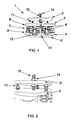
- Figure 1 shows a general view of the new vibration levelling and damping system (1) in accordance with the present invention.
- the lower (4), intermediate (3) and upper (2) platforms may be seen in the drawing.
- the upper platform (2) is joined to the central grub screw (10) and has a nut (14) and locking nut for its fixing to the above-mentioned platform (2 above). Though not observed in the drawing, it also has the corresponding washers.
- the perimetral grub screws (11) that jut out above and below the intermediate platform (3) may also be seen. These perimetral grub screws (11) also have locking nut and washer.
- Below the intermediate platform (3) the damping units (7) are located below the intermediate platform (3).
- damping units (7) each of which comprises four elastic devices, in this case springs (15). These springs are fixed to the upper (8) and lower (9) plates, and rest on bases (16) of India rubber or rubber. Bolts or screws (12) that fix the damping units (7) to the lower platform (4) are fitted to flaps that jut out from the lower plate (9) of the damping units (7). Though it is not observed in the drawing, there are also means to fix the units (7) to the intermediate platform (3).
- the lateral stabilizers (6), four per each damping unit (7), may also be seen.
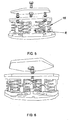
- lateral stabilizers (6) consist in rectangular-shaped flaps that jut out from the outer edges of the upper (8) and lower (9) plates, as may more closely be appreciated in Figure 5 .
- the upper and lower lateral flaps remain face to face, restricting lateral movements of the unit (7).
- the overall effect on the complete system (1) is the restriction of system movement (1) that is different from its natural vertical-direction working movement. In this way, problems that arise when sudden movement of machines due to hammering suffered by the starting of certain machines, such as large electrical engines, for example, are resolved.
- the elastic base pad on the bottom (5) may also be seen under the bottom plate of the system, fixed to the lower surface of the lower platform (4).
- This bottom elastic base pad (4) enables the system (1) to support itself better on the surface where it is going to work, in the case where it is rough or not completely clean.
- the lower platform (4) is fixed to the working area by means of suitable bolts or screws, which do not appear in the drawings.
- the desired height of the upper platform (2) is adjusted by the central grub screw (10) and is fixed to it by using a nut (14) and locking nut, with their corresponding washers.
- the height of the perimetral grub screws (11) is adjusted until they touch the lower surface of the upper platform (2) and situated at the suitable position to obtain the desired inclination angle of the upper platform (2).
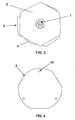
- Figure 3 shows an upper view of the system (1) in accordance with the present invention.
- the upper platform (2) may be observed in the foreground, and, almost completely covered by it, part of the edge of the intermediate platform (3) and part of the edge of the lower platform (4) may be seen.
- the central grub screw (10) may also be seen.
- Figure 4 shows a lower view of the system (1) in accordance with the present invention, where the bottom elastic pad (5) and lower platform (4) screw holes (13) may be seen.
- Figure 5 shows another general view of the system (1) in accordance with the present invention.
- Figure 6 shows another general view of the system (1) in accordance with the present invention, from a close-up angle.
Landscapes
- Engineering & Computer Science (AREA)
- General Engineering & Computer Science (AREA)
- Mechanical Engineering (AREA)
- Architecture (AREA)
- Aviation & Aerospace Engineering (AREA)
- Physics & Mathematics (AREA)
- Acoustics & Sound (AREA)
- Civil Engineering (AREA)
- Structural Engineering (AREA)
- Vibration Prevention Devices (AREA)
- Buildings Adapted To Withstand Abnormal External Influences (AREA)
- Machine Tool Units (AREA)
- Vehicle Body Suspensions (AREA)
- Fluid-Damping Devices (AREA)
Claims (16)
- Un système vibrant de nivellement et d'amortissement (1) qui comprend une plateforme inférieure (4), une plateforme intermédiaire (3), des unités d'amortissement (7) fixées entre les deux plateformes et une vis sans tête centrale (10) qui est assemblée à la plateforme intermédiaire (3), le système comprenant une plateforme supérieure (2) assemblée à la vis sans tête centrale (10), caractérisé en ce que le système comprend en outre au moins, trois vis sans tête périphériques (11) pour niveler la plateforme supérieure (2) mentionnée ci-dessus.
- Le système (1), conformément à la revendication 1, où les vis sans tête périphériques (11) sont assemblées à la plateforme intermédiaire (3).
- Le système (1), conformément à n'importe laquelle des revendications précédentes, où les vis sans tête périphériques (11) sont ajustées en hauteur à la plateforme supérieure (2).
- Le système (1), conformément à n'importe laquelle des revendications précédentes, où la plateforme supérieure comporte un trou central pour assembler la vis sans tête centrale.
- Le système (1), conformément à n'importe laquelle des revendications précédentes, où la plateforme intermédiaire (3) comporte des trous pour les vis sans tête périphériques (11) et la vis sans tête centrale (10).
- Le système (1), conformément à n'importe laquelle des revendications précédentes, où la plateforme inférieure (4) comporte des trous (13) pour sa fixation au sol ou au mur et pour fixer les unités d'amortissement (7).
- Le système (1), conformément à n'importe laquelle des revendications précédentes, où les plateformes inférieure (4), intermédiaire (3) et supérieure (2) sont fabriquées en métal.
- Le système (1), conformément à n'importe laquelle des revendications précédentes, caractérisé en ce qu'il possède au moins trois unités d'amortissement (7).
- Le système (1), conformément à la revendication 8, où les unités d'amortissement (7) comprennent un ou plusieurs dispositifs élastiques (15).
- Le système (1), conformément à la revendication 9, où les unités d'amortissement (7) sont constituées de deux plaques, supérieure (8) et inférieure (9), entre lesquelles les dispositifs élastiques (15) sont insérés.
- Le système (1), conformément à la revendication 9 ou 10, où les unités d'amortissement (7) comprennent également des stabilisateurs latéraux (6).
- Le système (1), conformément à n'importe laquelle des revendications 9 à 11, où les unités d'amortissement (7) possèdent de 2 à 6 dispositifs élastiques (15).
- Le système (1), conformément à la revendication 12, où les dispositifs d'amortissement (7) possèdent quatre dispositifs élastiques (15).
- Le système (1), conformément à n'importe laquelle des revendications 9 à 13, où les dispositifs élastiques (15) sont des ressorts.
- Le système (1), conformément à n'importe laquelle des revendications précédentes, qui comprend également un patin élastique inférieur (5) fixé à la surface inférieure de la plateforme inférieure (4).
- Le système (1), conformément à la revendication 15, où le patin élastique inférieur (5) est fabriqué en caoutchouc.
Applications Claiming Priority (1)
| Application Number | Priority Date | Filing Date | Title |
|---|---|---|---|
| ES200602551A ES2302445B1 (es) | 2006-10-06 | 2006-10-06 | Nuevo sistema de nivelacion y de amortiguacion de vibraciones. |
Publications (3)
| Publication Number | Publication Date |
|---|---|
| EP1908983A2 EP1908983A2 (fr) | 2008-04-09 |
| EP1908983A3 EP1908983A3 (fr) | 2008-04-16 |
| EP1908983B1 true EP1908983B1 (fr) | 2010-03-17 |
Family
ID=38777705
Family Applications (1)
| Application Number | Title | Priority Date | Filing Date |
|---|---|---|---|
| EP06125135A Active EP1908983B1 (fr) | 2006-10-06 | 2006-11-30 | Système de mise à niveau et d'amortissement de vibrations |
Country Status (4)
| Country | Link |
|---|---|
| EP (1) | EP1908983B1 (fr) |
| AT (1) | ATE461381T1 (fr) |
| DE (1) | DE602006012987D1 (fr) |
| ES (2) | ES2302445B1 (fr) |
Cited By (1)
| Publication number | Priority date | Publication date | Assignee | Title |
|---|---|---|---|---|
| CN106051041A (zh) * | 2016-05-24 | 2016-10-26 | 蚌埠学院 | 一种减振装置 |
Families Citing this family (8)
| Publication number | Priority date | Publication date | Assignee | Title |
|---|---|---|---|---|
| ITMI20130982A1 (it) * | 2013-06-14 | 2014-12-15 | Soleco Engineering Srl | Supporto antivibrante con dispositivo di regolazione interna |
| FI125062B (fi) * | 2013-12-05 | 2015-05-15 | Metso Minerals Inc | Jousen kiristyslaite, leukamurskain, mineraalimateriaalin prosessointilaitos ja menetelmä palautintankoa kuormittavan jousen supistamiseksi tai laajentamiseksi leukamurskaimessa |
| FI125063B (fi) * | 2013-12-05 | 2015-05-15 | Metso Minerals Inc | Kiristyselin, kiristyslaite, leukamurskain, mineraalimateriaalin prosessointilaitos ja menetelmä kulutusosan kireyden säätämiseksi |
| CN108372978A (zh) * | 2018-02-22 | 2018-08-07 | 安徽永裕云商企业管理有限公司 | 一种办公设备转运输送装置 |
| CN111503438A (zh) * | 2020-05-25 | 2020-08-07 | 国网河北省电力有限公司邢台供电分公司 | 一种新型电力通信设备保护装置 |
| CN116446551B (zh) * | 2023-05-10 | 2025-11-25 | 同济大学 | 弯曲振动控制的三维组合隔震支座 |
| CN116872185B (zh) * | 2023-08-18 | 2025-08-19 | 北京半导体专用设备研究所(中国电子科技集团公司第四十五研究所) | 调平机构及晶圆传输机械手 |
| CN119554525B (zh) * | 2025-01-27 | 2025-06-03 | 太高控股有限公司 | 一种可快速安装的矿用设备定位装置及使用方法 |
Family Cites Families (7)
| Publication number | Priority date | Publication date | Assignee | Title |
|---|---|---|---|---|
| US2468043A (en) * | 1945-10-31 | 1949-04-26 | Charles E Crede | Article supporting structure |
| FR1479413A (fr) * | 1966-03-21 | 1967-05-05 | Robatel & Mulatier Atel | Perfectionnements aux suspensions élastiques pour essoreuses centrifuges et applications analogues |
| DE2019348A1 (de) * | 1970-04-22 | 1971-11-04 | Isoliertechnik Horst Grassmann | Stahlfederisolator |
| DE7617012U1 (de) * | 1976-05-28 | 1978-06-29 | Wolf, Hans, 3300 Braunschweig | Schwingungsdämpfer mit Stellvorrichtung für Maschinen |
| US4846436A (en) * | 1987-06-08 | 1989-07-11 | Vibro Dynamics Corporation | Power assisted equipment mounting system |
| DE10205788B4 (de) * | 2002-02-13 | 2007-06-14 | Bundesrepublik Deutschland, vertreten durch das Bundesministerium der Verteidigung, dieses vertreten durch den Präsidenten des Bundesamtes für Wehrtechnik und Beschaffung | Lagefixierte, schockelastische Lagerung |
| ES2321511T3 (es) * | 2003-12-23 | 2009-06-08 | Suspensiones Elasticas Del Norte, S.L. | Amortiguador acustico ajustable. |
-
2006
- 2006-10-06 ES ES200602551A patent/ES2302445B1/es not_active Expired - Fee Related
- 2006-11-30 DE DE602006012987T patent/DE602006012987D1/de active Active
- 2006-11-30 ES ES06125135T patent/ES2343076T3/es active Active
- 2006-11-30 EP EP06125135A patent/EP1908983B1/fr active Active
- 2006-11-30 AT AT06125135T patent/ATE461381T1/de not_active IP Right Cessation
Cited By (1)
| Publication number | Priority date | Publication date | Assignee | Title |
|---|---|---|---|---|
| CN106051041A (zh) * | 2016-05-24 | 2016-10-26 | 蚌埠学院 | 一种减振装置 |
Also Published As
| Publication number | Publication date |
|---|---|
| ES2302445B1 (es) | 2009-05-05 |
| ES2302445A1 (es) | 2008-07-01 |
| EP1908983A2 (fr) | 2008-04-09 |
| ATE461381T1 (de) | 2010-04-15 |
| DE602006012987D1 (de) | 2010-04-29 |
| ES2343076T3 (es) | 2010-07-22 |
| EP1908983A3 (fr) | 2008-04-16 |
Similar Documents
| Publication | Publication Date | Title |
|---|---|---|
| KR101193469B1 (ko) | 내진장치를 구비하고 수평조절이 용이한 배전반(고압 배전반, 저압 배전반, 분전반, mcc) | |
| EP1908983B1 (fr) | Système de mise à niveau et d'amortissement de vibrations | |
| US5573220A (en) | Adjustable vibration absorbing machinery foundation mount and method for tuning the same | |
| KR101712803B1 (ko) | 내진기능을 갖는 천장용 행거장치 | |
| JP2009541626A (ja) | 地震に対して安定したフローリング | |
| KR101737822B1 (ko) | 방진 성능 및 내진 성능을 갖춘 배전반 | |
| US4281739A (en) | Damping body for machine support arrangements | |
| JPH10231894A (ja) | 一定の水平方向固有振動数の振動を絶縁するマウントパッドインサート | |
| JP5947696B2 (ja) | 緩み止め具及び当該緩み止め具を備えた減震ストッパ構造 | |
| JP6209784B2 (ja) | 減震ストッパ構造並びに当該減震ストッパ構造を備えた防振架台 | |
| KR100983630B1 (ko) | 높이 조절이 가능한 마루틀 고정장치 | |
| JP5973864B2 (ja) | 隙間管理具 | |
| JPH07139589A (ja) | 防振架台 | |
| JP5972309B2 (ja) | 免震装置、及び免震工法 | |
| KR20160087789A (ko) | 내진장치를 구비하고 수평조절이 용이한 배전반 | |
| KR20200077121A (ko) | 방진완충기능을 갖는 무용접 무피스 데크로드시스템 | |
| CN217422014U (zh) | 建筑工程用机电设备减震装置 | |
| KR101752828B1 (ko) | 내진 기능을 갖는 전기케이블 트레이 고정대 | |
| KR101795927B1 (ko) | 진동 흡수 댐퍼 | |
| KR102226293B1 (ko) | 마루틀 고정장치 | |
| RU2269700C1 (ru) | Виброизолятор рессорного типа | |
| JP4503493B2 (ja) | 薄型制振装置及び制振システム | |
| KR101613567B1 (ko) | 방진 마운트 | |
| KR102174840B1 (ko) | 방진 장치 | |
| JP3239830U (ja) | 変換器バルブ構成 |
Legal Events
| Date | Code | Title | Description |
|---|---|---|---|
| PUAI | Public reference made under article 153(3) epc to a published international application that has entered the european phase |
Free format text: ORIGINAL CODE: 0009012 |
|
| PUAL | Search report despatched |
Free format text: ORIGINAL CODE: 0009013 |
|
| AK | Designated contracting states |
Kind code of ref document: A2 Designated state(s): AT BE BG CH CY CZ DE DK EE ES FI FR GB GR HU IE IS IT LI LT LU LV MC NL PL PT RO SE SI SK TR |
|
| AX | Request for extension of the european patent |
Extension state: AL BA HR MK RS |
|
| AK | Designated contracting states |
Kind code of ref document: A3 Designated state(s): AT BE BG CH CY CZ DE DK EE ES FI FR GB GR HU IE IS IT LI LT LU LV MC NL PL PT RO SE SI SK TR |
|
| AX | Request for extension of the european patent |
Extension state: AL BA HR MK RS |
|
| RIC1 | Information provided on ipc code assigned before grant |
Ipc: F16F 3/00 20060101ALI20080311BHEP Ipc: F16F 3/10 20060101AFI20071213BHEP |
|
| 17P | Request for examination filed |
Effective date: 20080806 |
|
| AKX | Designation fees paid |
Designated state(s): AT BE BG CH CY CZ DE DK EE ES FI FR GB GR HU IE IS IT LI LT LU LV MC NL PL PT RO SE SI SK TR |
|
| RAP1 | Party data changed (applicant data changed or rights of an application transferred) |
Owner name: SUSPENSIONES ELASTICAS DEL NORTE, S.L. |
|
| GRAP | Despatch of communication of intention to grant a patent |
Free format text: ORIGINAL CODE: EPIDOSNIGR1 |
|
| RIC1 | Information provided on ipc code assigned before grant |
Ipc: F16F 3/10 20060101AFI20091019BHEP Ipc: F16F 15/067 20060101ALN20091019BHEP Ipc: F16F 3/00 20060101ALI20091019BHEP |
|
| RTI1 | Title (correction) |
Free format text: LEVELLING AND DAMPING SYSTEM FOR VIBRATIONS |
|
| GRAS | Grant fee paid |
Free format text: ORIGINAL CODE: EPIDOSNIGR3 |
|
| GRAA | (expected) grant |
Free format text: ORIGINAL CODE: 0009210 |
|
| AK | Designated contracting states |
Kind code of ref document: B1 Designated state(s): AT BE BG CH CY CZ DE DK EE ES FI FR GB GR HU IE IS IT LI LT LU LV MC NL PL PT RO SE SI SK TR |
|
| REG | Reference to a national code |
Ref country code: GB Ref legal event code: FG4D |
|
| REG | Reference to a national code |
Ref country code: CH Ref legal event code: EP |
|
| REG | Reference to a national code |
Ref country code: IE Ref legal event code: FG4D |
|
| REF | Corresponds to: |
Ref document number: 602006012987 Country of ref document: DE Date of ref document: 20100429 Kind code of ref document: P |
|
| REG | Reference to a national code |
Ref country code: NL Ref legal event code: VDEP Effective date: 20100317 |
|
| REG | Reference to a national code |
Ref country code: ES Ref legal event code: FG2A Ref document number: 2343076 Country of ref document: ES Kind code of ref document: T3 |
|
| PG25 | Lapsed in a contracting state [announced via postgrant information from national office to epo] |
Ref country code: LT Free format text: LAPSE BECAUSE OF FAILURE TO SUBMIT A TRANSLATION OF THE DESCRIPTION OR TO PAY THE FEE WITHIN THE PRESCRIBED TIME-LIMIT Effective date: 20100317 |
|
| LTIE | Lt: invalidation of european patent or patent extension |
Effective date: 20100317 |
|
| PG25 | Lapsed in a contracting state [announced via postgrant information from national office to epo] |
Ref country code: FI Free format text: LAPSE BECAUSE OF FAILURE TO SUBMIT A TRANSLATION OF THE DESCRIPTION OR TO PAY THE FEE WITHIN THE PRESCRIBED TIME-LIMIT Effective date: 20100317 Ref country code: AT Free format text: LAPSE BECAUSE OF FAILURE TO SUBMIT A TRANSLATION OF THE DESCRIPTION OR TO PAY THE FEE WITHIN THE PRESCRIBED TIME-LIMIT Effective date: 20100317 Ref country code: LV Free format text: LAPSE BECAUSE OF FAILURE TO SUBMIT A TRANSLATION OF THE DESCRIPTION OR TO PAY THE FEE WITHIN THE PRESCRIBED TIME-LIMIT Effective date: 20100317 Ref country code: PL Free format text: LAPSE BECAUSE OF FAILURE TO SUBMIT A TRANSLATION OF THE DESCRIPTION OR TO PAY THE FEE WITHIN THE PRESCRIBED TIME-LIMIT Effective date: 20100317 Ref country code: SI Free format text: LAPSE BECAUSE OF FAILURE TO SUBMIT A TRANSLATION OF THE DESCRIPTION OR TO PAY THE FEE WITHIN THE PRESCRIBED TIME-LIMIT Effective date: 20100317 |
|
| PG25 | Lapsed in a contracting state [announced via postgrant information from national office to epo] |
Ref country code: SE Free format text: LAPSE BECAUSE OF FAILURE TO SUBMIT A TRANSLATION OF THE DESCRIPTION OR TO PAY THE FEE WITHIN THE PRESCRIBED TIME-LIMIT Effective date: 20100317 Ref country code: BE Free format text: LAPSE BECAUSE OF FAILURE TO SUBMIT A TRANSLATION OF THE DESCRIPTION OR TO PAY THE FEE WITHIN THE PRESCRIBED TIME-LIMIT Effective date: 20100317 Ref country code: CY Free format text: LAPSE BECAUSE OF FAILURE TO SUBMIT A TRANSLATION OF THE DESCRIPTION OR TO PAY THE FEE WITHIN THE PRESCRIBED TIME-LIMIT Effective date: 20100317 Ref country code: EE Free format text: LAPSE BECAUSE OF FAILURE TO SUBMIT A TRANSLATION OF THE DESCRIPTION OR TO PAY THE FEE WITHIN THE PRESCRIBED TIME-LIMIT Effective date: 20100317 Ref country code: GR Free format text: LAPSE BECAUSE OF FAILURE TO SUBMIT A TRANSLATION OF THE DESCRIPTION OR TO PAY THE FEE WITHIN THE PRESCRIBED TIME-LIMIT Effective date: 20100618 Ref country code: NL Free format text: LAPSE BECAUSE OF FAILURE TO SUBMIT A TRANSLATION OF THE DESCRIPTION OR TO PAY THE FEE WITHIN THE PRESCRIBED TIME-LIMIT Effective date: 20100317 Ref country code: RO Free format text: LAPSE BECAUSE OF FAILURE TO SUBMIT A TRANSLATION OF THE DESCRIPTION OR TO PAY THE FEE WITHIN THE PRESCRIBED TIME-LIMIT Effective date: 20100317 |
|
| PG25 | Lapsed in a contracting state [announced via postgrant information from national office to epo] |
Ref country code: SK Free format text: LAPSE BECAUSE OF FAILURE TO SUBMIT A TRANSLATION OF THE DESCRIPTION OR TO PAY THE FEE WITHIN THE PRESCRIBED TIME-LIMIT Effective date: 20100317 Ref country code: BG Free format text: LAPSE BECAUSE OF FAILURE TO SUBMIT A TRANSLATION OF THE DESCRIPTION OR TO PAY THE FEE WITHIN THE PRESCRIBED TIME-LIMIT Effective date: 20100617 Ref country code: CZ Free format text: LAPSE BECAUSE OF FAILURE TO SUBMIT A TRANSLATION OF THE DESCRIPTION OR TO PAY THE FEE WITHIN THE PRESCRIBED TIME-LIMIT Effective date: 20100317 Ref country code: IS Free format text: LAPSE BECAUSE OF FAILURE TO SUBMIT A TRANSLATION OF THE DESCRIPTION OR TO PAY THE FEE WITHIN THE PRESCRIBED TIME-LIMIT Effective date: 20100717 |
|
| PLBE | No opposition filed within time limit |
Free format text: ORIGINAL CODE: 0009261 |
|
| STAA | Information on the status of an ep patent application or granted ep patent |
Free format text: STATUS: NO OPPOSITION FILED WITHIN TIME LIMIT |
|
| PG25 | Lapsed in a contracting state [announced via postgrant information from national office to epo] |
Ref country code: DK Free format text: LAPSE BECAUSE OF FAILURE TO SUBMIT A TRANSLATION OF THE DESCRIPTION OR TO PAY THE FEE WITHIN THE PRESCRIBED TIME-LIMIT Effective date: 20100317 Ref country code: PT Free format text: LAPSE BECAUSE OF FAILURE TO SUBMIT A TRANSLATION OF THE DESCRIPTION OR TO PAY THE FEE WITHIN THE PRESCRIBED TIME-LIMIT Effective date: 20100719 |
|
| 26N | No opposition filed |
Effective date: 20101220 |
|
| PG25 | Lapsed in a contracting state [announced via postgrant information from national office to epo] |
Ref country code: IT Free format text: LAPSE BECAUSE OF FAILURE TO SUBMIT A TRANSLATION OF THE DESCRIPTION OR TO PAY THE FEE WITHIN THE PRESCRIBED TIME-LIMIT Effective date: 20100317 |
|
| PG25 | Lapsed in a contracting state [announced via postgrant information from national office to epo] |
Ref country code: MC Free format text: LAPSE BECAUSE OF NON-PAYMENT OF DUE FEES Effective date: 20101130 |
|
| REG | Reference to a national code |
Ref country code: CH Ref legal event code: PL |
|
| GBPC | Gb: european patent ceased through non-payment of renewal fee |
Effective date: 20101130 |
|
| PG25 | Lapsed in a contracting state [announced via postgrant information from national office to epo] |
Ref country code: CH Free format text: LAPSE BECAUSE OF NON-PAYMENT OF DUE FEES Effective date: 20101130 Ref country code: LI Free format text: LAPSE BECAUSE OF NON-PAYMENT OF DUE FEES Effective date: 20101130 |
|
| REG | Reference to a national code |
Ref country code: FR Ref legal event code: ST Effective date: 20110801 |
|
| REG | Reference to a national code |
Ref country code: DE Ref legal event code: R119 Ref document number: 602006012987 Country of ref document: DE Effective date: 20110601 Ref country code: DE Ref legal event code: R119 Ref document number: 602006012987 Country of ref document: DE Effective date: 20110531 |
|
| PG25 | Lapsed in a contracting state [announced via postgrant information from national office to epo] |
Ref country code: FR Free format text: LAPSE BECAUSE OF NON-PAYMENT OF DUE FEES Effective date: 20101130 Ref country code: IE Free format text: LAPSE BECAUSE OF NON-PAYMENT OF DUE FEES Effective date: 20101130 |
|
| PG25 | Lapsed in a contracting state [announced via postgrant information from national office to epo] |
Ref country code: GB Free format text: LAPSE BECAUSE OF NON-PAYMENT OF DUE FEES Effective date: 20101130 |
|
| PG25 | Lapsed in a contracting state [announced via postgrant information from national office to epo] |
Ref country code: HU Free format text: LAPSE BECAUSE OF FAILURE TO SUBMIT A TRANSLATION OF THE DESCRIPTION OR TO PAY THE FEE WITHIN THE PRESCRIBED TIME-LIMIT Effective date: 20100918 Ref country code: LU Free format text: LAPSE BECAUSE OF NON-PAYMENT OF DUE FEES Effective date: 20101130 |
|
| PG25 | Lapsed in a contracting state [announced via postgrant information from national office to epo] |
Ref country code: TR Free format text: LAPSE BECAUSE OF FAILURE TO SUBMIT A TRANSLATION OF THE DESCRIPTION OR TO PAY THE FEE WITHIN THE PRESCRIBED TIME-LIMIT Effective date: 20100317 |
|
| PG25 | Lapsed in a contracting state [announced via postgrant information from national office to epo] |
Ref country code: DE Free format text: LAPSE BECAUSE OF NON-PAYMENT OF DUE FEES Effective date: 20110531 |
|
| PGFP | Annual fee paid to national office [announced via postgrant information from national office to epo] |
Ref country code: ES Payment date: 20251202 Year of fee payment: 20 |