EP1908973A2 - Interface de moments dans un entraînement de véhicule automobile - Google Patents
Interface de moments dans un entraînement de véhicule automobile Download PDFInfo
- Publication number
- EP1908973A2 EP1908973A2 EP07017444A EP07017444A EP1908973A2 EP 1908973 A2 EP1908973 A2 EP 1908973A2 EP 07017444 A EP07017444 A EP 07017444A EP 07017444 A EP07017444 A EP 07017444A EP 1908973 A2 EP1908973 A2 EP 1908973A2
- Authority
- EP
- European Patent Office
- Prior art keywords
- locking pin
- flange
- support plate
- motor vehicle
- torque interface
- Prior art date
- Legal status (The legal status is an assumption and is not a legal conclusion. Google has not performed a legal analysis and makes no representation as to the accuracy of the status listed.)
- Granted
Links
Images

Classifications
-
- F—MECHANICAL ENGINEERING; LIGHTING; HEATING; WEAPONS; BLASTING
- F16—ENGINEERING ELEMENTS AND UNITS; GENERAL MEASURES FOR PRODUCING AND MAINTAINING EFFECTIVE FUNCTIONING OF MACHINES OR INSTALLATIONS; THERMAL INSULATION IN GENERAL
- F16D—COUPLINGS FOR TRANSMITTING ROTATION; CLUTCHES; BRAKES
- F16D1/00—Couplings for rigidly connecting two coaxial shafts or other movable machine elements
- F16D1/06—Couplings for rigidly connecting two coaxial shafts or other movable machine elements for attachment of a member on a shaft or on a shaft-end
- F16D1/08—Couplings for rigidly connecting two coaxial shafts or other movable machine elements for attachment of a member on a shaft or on a shaft-end with clamping hub; with hub and longitudinal key
- F16D1/0894—Couplings for rigidly connecting two coaxial shafts or other movable machine elements for attachment of a member on a shaft or on a shaft-end with clamping hub; with hub and longitudinal key with other than axial keys, e.g. diametral pins, cotter pins and no other radial clamping
-
- F—MECHANICAL ENGINEERING; LIGHTING; HEATING; WEAPONS; BLASTING
- F16—ENGINEERING ELEMENTS AND UNITS; GENERAL MEASURES FOR PRODUCING AND MAINTAINING EFFECTIVE FUNCTIONING OF MACHINES OR INSTALLATIONS; THERMAL INSULATION IN GENERAL
- F16D—COUPLINGS FOR TRANSMITTING ROTATION; CLUTCHES; BRAKES
- F16D1/00—Couplings for rigidly connecting two coaxial shafts or other movable machine elements
- F16D1/10—Quick-acting couplings in which the parts are connected by simply bringing them together axially
- F16D1/108—Quick-acting couplings in which the parts are connected by simply bringing them together axially having retaining means rotating with the coupling and acting by interengaging parts, i.e. positive coupling
-
- F—MECHANICAL ENGINEERING; LIGHTING; HEATING; WEAPONS; BLASTING
- F16—ENGINEERING ELEMENTS AND UNITS; GENERAL MEASURES FOR PRODUCING AND MAINTAINING EFFECTIVE FUNCTIONING OF MACHINES OR INSTALLATIONS; THERMAL INSULATION IN GENERAL
- F16D—COUPLINGS FOR TRANSMITTING ROTATION; CLUTCHES; BRAKES
- F16D2300/00—Special features for couplings or clutches
- F16D2300/12—Mounting or assembling
Definitions
- the invention relates to a torque interface for transmitting torque in a drive train of a motor vehicle with a particular driven by an internal combustion engine of the motor vehicle flange, a spring element and a flange on the spring element relatively rotatably resiliently associated support plate.
- Torque interfaces in a powertrain of a motor vehicle can be used to transmit a torque generated by an internal combustion engine.
- a torque interface for transmitting a torque for coupling a dual-mass flywheel to a coupling unit of the drive train of the motor vehicle.
- the output unit can be, for example, a double clutch.
- the object of the invention is to provide an alternative, in particular improved, torque interface for transmitting a torque in a drive train of a motor vehicle.
- the object is achieved with a torque interface for transmitting torque in a drive train of a motor vehicle with a particular driven by an internal combustion engine of the motor vehicle flange, a spring element and a flange on the spring element relatively rotatably resiliently associated support plate in that for mounting the torque interface, the support plate can be locked in rotation with the flange via a locking pin against a restoring force of the spring element. It is therefore possible to keep the spring element biased over the locking pin.
- the support plate relative to the flange rotatably positioned against the restoring force of the spring element and locked there, so that for further use of the torque interface, for example, for connecting the flange and the support plate to another unit of the drive train, the spring force of the spring element no longer must be overcome.
- a connection of the coupled to the support plate flange to other units of the drive train is free of possibly caused by the spring element clamping forces, ie without jamming or with game possible.
- a preferred embodiment is characterized in that the flange has a substantially radially extending first slot, and that the support plate has a substantially extending in the circumferential direction and substantially radially pointing inwardly angled extending second slot, said locking pin in the first and second Slot engages.
- the slots thus overlap at least partially, so that can pass through them through the locking pin.
- the locking pin abut on corresponding flanks of the slots and thus lock the flange against rotation relative to the support plate.
- Another embodiment is characterized in that the locking pin engages in the first and second slot with clearance.
- the locking pin is freely movable in the slots without significant frictional forces, in particular as far as the flange and the support plate are brought into a rotational position relative to each other, in which the locking pin is powerless, so does not hit the corresponding edges of the slots.
- Another embodiment is characterized in that the locking pin is adjustable between a locking position and a release position.
- the locking pin is adjustable between a locking position and a release position.
- the locking pin can be rotated by the choice of the position of the locking pin of the flange in the release position within certain limits relative to the support plate or locked in the locking position corresponding to the restoring forces of the spring element rotatably.
- a further embodiment is characterized in that the locking pin centrifugally, spring force and / or magnetic force supported by the locking position in the release position is adjustable. This makes it possible, for example, after connection of the torque interface to the output unit, to adjust the locking pin in its release position to make the torque interface operational.
- a further embodiment is characterized in that the locking pin during operation of the motor vehicle is adjustable from the locking position to the release position.
- the locking pin is initially still in the locked position. Only at a later time, for example, at the first start of the motor vehicle, then the locking pin are moved from its locking position to the release position. This can advantageously be done, for example, without further action, only depending on a specific operating state of the motor vehicle. This can advantageously be done for example by the centrifugal forces occurring within the drive train.
- the locking pin is jammed in the train operation of the motor vehicle on the slots, in addition, the flange and the support plate must be relatively rotated to each other that triggers the occurring, caused by the spring element frictional engagement of the locking pin within the slots.
- the locking pin can be adjusted by its radially further inward locking position in its radially outer unlocking position. Thereafter, the locking pin is inoperative and the torque interface is completely established. However, it is possible to lock the locking pins again at a later time, for example during a workshop visit.
- a further preferred embodiment is characterized in that the flange has a first internal toothing for the rotationally fixed connection of the torque interface to an external toothing of an output unit of the drive train, and that the support plate has a second internal toothing engaging in the first internal toothing.
- the second internal toothing of the support plate presses the outer toothing of the output unit without play against the first internal toothing on the tension side via the spring element coupled to the support plate when the torque interface is connected and the locking pin is unlocked.
- a toothing-free toothing of the first and second internal toothing with the external toothing of the output unit can be effected in accordance with the torque exerted by the spring element.
- a backlash-free toothing up to about 60 Nm can be effective.
- a thrust torque occurring within the drive train of about 60 Nm or more is required for the first time. If the torque fluctuations move below the maximum value provided by the spring element, the first internal toothing of the flange is always pressed against the external toothing of the output unit of the drive train via the spring element and by means of the second internal toothing engaging in the first internal toothing.
- the object is also achieved by a drive train of a motor vehicle with a torque interface described above.
- the object is further achieved by a motor vehicle with a drive train described above.
- the object is finally achieved by a method for mounting a torque interface of a drive train of a motor vehicle, in particular a torque interface described above, by the following steps: biasing the flange against the support plate on the spring element, rotationally fixed locking the flange with the support plate on the locking pin.
- the flange can be locked to the support plate via the locking pin. This can advantageously be exploited to mount the torque interface quasi powerless, so without having to overcome the spring force of the spring element, with the output unit of the drive train to assemble or manufacture.
- a preferred embodiment of the method is characterized by the following step: introducing a thrust torque in the torque interface via the drive train of the motor vehicle during operation of the motor vehicle and thereby unlocking the locking pin. It is thus possible to release the locking pin almost without further action during operation, in particular during the first start-up of the motor vehicle, merely by introducing a thrust moment.
- Another preferred embodiment of the method is characterized by the following step: unlocking the locking pin, centrifugal, magnetic force and / or spring assisted.
- the locking pin can almost automatically be unlocked during operation.
- magnetic and / or spring forces can advantageously also serve additionally and / or supportively for this purpose.
- a further preferred embodiment of the method is characterized by the following step: displacing the locking pin radially outward for unlocking the locking pin. Since the centrifugal forces occurring in the drive train always act radially outwards, these can be advantageously utilized for the displacement and thus simultaneous unlocking of the securing pin.
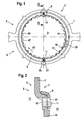
- FIG. 1 shows a plan view of a torque interface 1 for transmitting a torque in a drive train 3 of a motor vehicle 5.
- Figure 2 shows a partial section along the line II - 11 of Figure 1 with a flange 7, a support plate 9 and a locking pin 11.
- the flange 7 has a first internal toothing 15.
- the support plate 9 has a second internal toothing 17 which engages by means of tabs 19 in the first internal toothing 15 of the flange 7.
- Figure 1 shows the flange 7 in a relative rotational position to the support plate 9, wherein the locking pin 11 is in a securing position.
- a corresponding external toothing of an output unit 21 of the drive train 3 can be introduced into the internal gears 15 and 17.
- the output unit 21 is indicated in Figure 2 by the reference numeral 21.
- the output unit 21 may be, for example, a clutch, for example a double clutch of the drive train 3 of the motor vehicle 5.
- FIG. 3 shows a detail marked with an X in FIG. 1.
- the securing pin 11 can be seen in a top view in three different positions relative to the flange 7 and to the support plate 9.
- An arrow 23 indicates the time sequence of the total of three shown in FIG Positions during an assembly process of the torque interface 1 on. Invisible lines are shown by dashed lines in FIG.
- the flange 7 has a first slot 25.
- the elongated hole 25 extends essentially in the radial direction, that is to say in its longitudinal extent it extends essentially along a radius of the drive train 3 of the motor vehicle 5.
- the support plate 9 has a second slot 27.
- the second slot 27 extends substantially along an imaginary circumference of the torque interface 1 of the drive train 3 of the motor vehicle 5, ie an imaginary line that is traversed by a certain point of the torque interface during a rotation.
- the second slot 27 extends at an angle 29 angled pointing substantially radially inward, ie pointing to a rotational axis 31 of the torque interface 1 of the drive train 3 of the motor vehicle 5 back.
- the locking pin 11 is located at a radially outer end of the first elongated hole 25 and at a left end of the second slot 27.
- a spring element which is connected between the flange 7 and the support plate 9 , essentially relaxed.
- the spring element is not shown in detail in Figures 1 to 4, but indicated in Figures 1 and 4 by a double arrow 33 indicating that the flange 7 is supported against the restoring force of the spring element relative to the support plate 9 rotatably.
- the locking pin 11 can be moved to a locking position, which is indicated by an arrow 37. In this locking position, the locking pin 11 is located at a, seen in alignment of Figure 3, the lower end of the first elongated hole 25 of the flange 7 and at a lower end of the second elongated hole 27 of the support plate. 9
- the locking pin 11 seen in its securing position, in alignment of Figure 3, the right side abuts a stop 39 of the first elongated hole 25 of the flange 7 and the left side on a second stop 41 of the second slot 27 of the support plate 9, so on the flanks of the slots 25 and 27 is frictionally clamped.
- the locking pin 11 is located in a radially inner position and prevented by means of the stops 39 and 41 caused by the restoring force of the spring element rotational movement of the flange 7 and the support plate 9.
- Figure 1 it can be seen that in this position of the flange. 7 to the support plate 9, the first internal toothing 15 and the second internal toothing 17 engage each other so that a corresponding external toothing of the output element 21 quasi powerless, so can be introduced with play.
- Figure 4 also shows the detail shown in Figure 3 of Figure 1, wherein the locking pin 11 is in an unlocked position.
- the locking pin 11 strikes a, seen in alignment of Figure 4, the upper end of the first elongated hole 25 of the flange 7 at.
- the double arrow 33 is indicated that the locking pin 11 can move freely within the second slot 27 of the support plate 9 while back and forth.
- a free movement of the flange 7 relative to the support plate 9 according to the coupling of the spring element is possible, as indicated by the double arrow 33.
- the outer toothing, not shown, of the output unit 21 strikes a thrust side 47 of the first internal toothing 15 of the flange 7.
- the tabs 19 of the second internal toothing 17 and the first internal toothing 15 are dimensioned such that the lugs 19 have thrust side play, so no thrust moment can break through the tabs 19 on the first internal toothing 15 of the flange 7.
- the locking pin 11 can be moved radially outward.
- This position is shown in Figure 4 and corresponds to the unlocking position of the locking pin 11. It can thus in a simple manner by moving the motor vehicle 5 in overrun the locking pin 11 of its locking position, as shown in Figure 3 on the right side, by the centrifugal forces occurring in his Unlocking position, as shown in Figure 4, are moved radially outward. If necessary, this movement can be assisted by magnetic forces and / or additional spring elements which can additionally act on the securing pin 11.
- the flange 7 can be biased against the support plate 9 via the spring element.
- the locking pin 11 By a corresponding displacement of the locking pin 11, as shown in Figure 3, then the flange 7 rotatably locked to the support plate 9.
- a thrust torque in the drive train 3 of the motor vehicle 5 can be initiated, for example during operation of the motor vehicle 5, preferably at the first commissioning of the motor vehicle 5.
- this means means in the drive train 3 occurring centrifugal forces, possibly supported by magnetic and / or spring forces happen.
- the locking pin 11 can be moved to unlock radially outward.
- one or more locking pins 11 may be provided.
- the spring element may have one or more compression springs, such as coil springs, which press the first internal teeth 15 and 17 of the flange 7 and the support plate 9 apart.
- compression springs such as coil springs
- they can be locked against each other by means of the locking pin 11 so that a non-illustrated driving ring of the output unit 21 quasi powerless in the internal gears 15 and 17, so with game introduced can be.
- the flange 7 passes the engine torque directly to the driving ring on.
- the carrier ring displaces the support plate 9, whereby the at least one securing pin 11 is relieved, ie becomes powerless , By the applied centrifugal force of at least one locking pin 11 is driven to the outside and thus gives the support plate 9 free.
- the support plate 9 is now unlocked and presses the flange 7 Anlagen profession, ie backlash against the driver ring of the output unit 21, not shown.
- the first internal teeth 15 of the flange 7 and the second internal teeth 17 of the support plate 9 are designed so that high shear moments (for example, impacts ) are passed directly from the driving ring in the first internal toothing 15 of the flange 7, without blocking the tabs 19 of the support plate 9.
Landscapes
- Engineering & Computer Science (AREA)
- General Engineering & Computer Science (AREA)
- Mechanical Engineering (AREA)
- Arrangement Or Mounting Of Propulsion Units For Vehicles (AREA)
- One-Way And Automatic Clutches, And Combinations Of Different Clutches (AREA)
- Mechanical Operated Clutches (AREA)
- Control Of Electric Motors In General (AREA)
- Hybrid Electric Vehicles (AREA)
Applications Claiming Priority (1)
| Application Number | Priority Date | Filing Date | Title |
|---|---|---|---|
| DE102006047301 | 2006-10-06 |
Publications (3)
| Publication Number | Publication Date |
|---|---|
| EP1908973A2 true EP1908973A2 (fr) | 2008-04-09 |
| EP1908973A3 EP1908973A3 (fr) | 2010-03-10 |
| EP1908973B1 EP1908973B1 (fr) | 2011-05-04 |
Family
ID=38884673
Family Applications (1)
| Application Number | Title | Priority Date | Filing Date |
|---|---|---|---|
| EP07017444A Not-in-force EP1908973B1 (fr) | 2006-10-06 | 2007-09-06 | Interface de moments dans un entraînement de véhicule automobile |
Country Status (3)
| Country | Link |
|---|---|
| EP (1) | EP1908973B1 (fr) |
| AT (1) | ATE508289T1 (fr) |
| DE (1) | DE502007007108D1 (fr) |
Cited By (1)
| Publication number | Priority date | Publication date | Assignee | Title |
|---|---|---|---|---|
| FR2982332A1 (fr) * | 2011-11-08 | 2013-05-10 | Valeo Embrayages | Ensemble de transmission de couple, en particulier pour vehicule automobile |
Families Citing this family (1)
| Publication number | Priority date | Publication date | Assignee | Title |
|---|---|---|---|---|
| WO2012031582A1 (fr) | 2010-09-09 | 2012-03-15 | Schaeffler Technologies Gmbh & Co. Kg | Dispositif de mise en tension pour une chaîne cinématique d'un véhicule à moteur |
Citations (3)
| Publication number | Priority date | Publication date | Assignee | Title |
|---|---|---|---|---|
| US2803474A (en) * | 1953-01-21 | 1957-08-20 | Wilson John Hart | Quick detachable joints |
| WO2007000131A2 (fr) * | 2005-06-28 | 2007-01-04 | Luk Lamellen Und Kupplungsbau Beteiligungs Kg | Systeme d'embrayage |
| WO2007000151A2 (fr) * | 2005-06-28 | 2007-01-04 | Luk Lamellen Und Kupplungsbau Beteiligungs Kg | Unite d'accouplement |
-
2007
- 2007-09-06 EP EP07017444A patent/EP1908973B1/fr not_active Not-in-force
- 2007-09-06 DE DE502007007108T patent/DE502007007108D1/de active Active
- 2007-09-06 AT AT07017444T patent/ATE508289T1/de active
Patent Citations (3)
| Publication number | Priority date | Publication date | Assignee | Title |
|---|---|---|---|---|
| US2803474A (en) * | 1953-01-21 | 1957-08-20 | Wilson John Hart | Quick detachable joints |
| WO2007000131A2 (fr) * | 2005-06-28 | 2007-01-04 | Luk Lamellen Und Kupplungsbau Beteiligungs Kg | Systeme d'embrayage |
| WO2007000151A2 (fr) * | 2005-06-28 | 2007-01-04 | Luk Lamellen Und Kupplungsbau Beteiligungs Kg | Unite d'accouplement |
Cited By (4)
| Publication number | Priority date | Publication date | Assignee | Title |
|---|---|---|---|---|
| FR2982332A1 (fr) * | 2011-11-08 | 2013-05-10 | Valeo Embrayages | Ensemble de transmission de couple, en particulier pour vehicule automobile |
| WO2013068689A1 (fr) * | 2011-11-08 | 2013-05-16 | Valeo Embrayages | Ensemble de transmission de couple, en particulier pour vehicule automobile |
| CN103930686A (zh) * | 2011-11-08 | 2014-07-16 | Valeo离合器公司 | 特别用于机动车的扭矩传递组件 |
| CN103930686B (zh) * | 2011-11-08 | 2018-02-27 | Valeo离合器公司 | 特别用于机动车的扭矩传递组件 |
Also Published As
| Publication number | Publication date |
|---|---|
| ATE508289T1 (de) | 2011-05-15 |
| EP1908973B1 (fr) | 2011-05-04 |
| EP1908973A3 (fr) | 2010-03-10 |
| DE502007007108D1 (de) | 2011-06-16 |
Similar Documents
| Publication | Publication Date | Title |
|---|---|---|
| EP3285904B1 (fr) | Dispositif de filtration | |
| EP3093516B1 (fr) | Systeme de serrage pour une chaine cinematique d'un vehicule automobile | |
| EP1834108B1 (fr) | Dispositif de blocage de couple de charge | |
| WO2007000131A2 (fr) | Systeme d'embrayage | |
| EP1862689B1 (fr) | Agencement de transmission d'un couple de rotation pour le conducteur de commande d'un véhicule | |
| DE3324999C2 (fr) | ||
| DE102006062833B4 (de) | Drehmomentübertragungseinrichtung | |
| DE3206623A1 (de) | Torsionsdaempfungsvorrichtung, insbesondere reibkupplung, insbesondere fuer kraftfahrzeuge | |
| WO2010060397A1 (fr) | Ensemble embrayage muni d'un dispositif de protection pour le transport | |
| EP2743541A2 (fr) | Dispositif de transmission de couple | |
| EP1908973B1 (fr) | Interface de moments dans un entraînement de véhicule automobile | |
| EP3365575B1 (fr) | Ensemble amortisseur de vibrations de torsion à embrayage, muni d'un embrayage de coupure hybride intégré dans un élément rotatif d'un amortisseur de vibrations de torsion | |
| DE2824718A1 (de) | Einer brennkraftmaschine nachgeschaltete schwungmasse | |
| DE102015120818B4 (de) | Getriebe mit schaltbarem Planetensatz sowie Freilaufkupplung für ein elektrisch antreibbares Kraftfahrzeug | |
| DE102020106248A1 (de) | Elektromotor-Getriebe-Anordnung mit einem Elektromotor mit integrierter Übersetzung; sowie Antriebseinheit | |
| DE19950597A1 (de) | Antriebsanordnung | |
| WO2020074269A1 (fr) | Dispositif d'accouplement à roue libre bidirectionnel commutable et dispositif d'entraînement destiné à un véhicule automobile muni dudit dispositif d'accouplement | |
| DE10003044A1 (de) | Torsionsschwingungsdämpfer | |
| DE19810918C2 (de) | Reibungskupplung | |
| DE102015121705A1 (de) | Kupplungsanordnung, insbesondere zum optionalen Verbinden eines Luftverdichters mit einer Antriebseinrichtung | |
| DE102018215162A1 (de) | Mehrscheibenkupplung | |
| DE102007008983B4 (de) | Vorrichtung zum Toleranzausgleich für eine Kupplung | |
| WO2018091022A1 (fr) | Dispositif de transmission de couple | |
| WO2018177462A1 (fr) | Dispositif d'embrayage pour une chaîne cinématique d'un véhicule | |
| DE102007042429A1 (de) | Momentenschnittstelle in einem Triebstrang eines Kraftfahrzeugs |
Legal Events
| Date | Code | Title | Description |
|---|---|---|---|
| PUAI | Public reference made under article 153(3) epc to a published international application that has entered the european phase |
Free format text: ORIGINAL CODE: 0009012 |
|
| AK | Designated contracting states |
Kind code of ref document: A2 Designated state(s): AT BE BG CH CY CZ DE DK EE ES FI FR GB GR HU IE IS IT LI LT LU LV MC MT NL PL PT RO SE SI SK TR |
|
| AX | Request for extension of the european patent |
Extension state: AL BA HR MK RS |
|
| RIN1 | Information on inventor provided before grant (corrected) |
Inventor name: ZHOU, BIN Inventor name: ZIERDEN, OLIVER Inventor name: MUELLER, JENS Inventor name: ZUEFLE, MARKUS Inventor name: JUNKER, ULI |
|
| PUAL | Search report despatched |
Free format text: ORIGINAL CODE: 0009013 |
|
| AK | Designated contracting states |
Kind code of ref document: A3 Designated state(s): AT BE BG CH CY CZ DE DK EE ES FI FR GB GR HU IE IS IT LI LT LU LV MC MT NL PL PT RO SE SI SK TR |
|
| AX | Request for extension of the european patent |
Extension state: AL BA HR MK RS |
|
| 17P | Request for examination filed |
Effective date: 20100910 |
|
| AKX | Designation fees paid |
Designated state(s): AT BE BG CH CY CZ DE DK EE ES FI FR GB GR HU IE IS IT LI LT LU LV MC MT NL PL PT RO SE SI SK TR |
|
| GRAP | Despatch of communication of intention to grant a patent |
Free format text: ORIGINAL CODE: EPIDOSNIGR1 |
|
| RIC1 | Information provided on ipc code assigned before grant |
Ipc: F16D 1/08 20060101AFI20101027BHEP Ipc: F16D 1/108 20060101ALI20101027BHEP |
|
| GRAS | Grant fee paid |
Free format text: ORIGINAL CODE: EPIDOSNIGR3 |
|
| GRAA | (expected) grant |
Free format text: ORIGINAL CODE: 0009210 |
|
| RAP1 | Party data changed (applicant data changed or rights of an application transferred) |
Owner name: SCHAEFFLER TECHNOLOGIES GMBH & CO. KG |
|
| AK | Designated contracting states |
Kind code of ref document: B1 Designated state(s): AT BE BG CH CY CZ DE DK EE ES FI FR GB GR HU IE IS IT LI LT LU LV MC MT NL PL PT RO SE SI SK TR |
|
| REG | Reference to a national code |
Ref country code: GB Ref legal event code: FG4D Free format text: NOT ENGLISH |
|
| REG | Reference to a national code |
Ref country code: CH Ref legal event code: EP |
|
| REG | Reference to a national code |
Ref country code: IE Ref legal event code: FG4D Free format text: LANGUAGE OF EP DOCUMENT: GERMAN |
|
| REF | Corresponds to: |
Ref document number: 502007007108 Country of ref document: DE Date of ref document: 20110616 Kind code of ref document: P |
|
| REG | Reference to a national code |
Ref country code: DE Ref legal event code: R096 Ref document number: 502007007108 Country of ref document: DE Effective date: 20110616 |
|
| REG | Reference to a national code |
Ref country code: NL Ref legal event code: VDEP Effective date: 20110504 |
|
| PG25 | Lapsed in a contracting state [announced via postgrant information from national office to epo] |
Ref country code: PT Free format text: LAPSE BECAUSE OF FAILURE TO SUBMIT A TRANSLATION OF THE DESCRIPTION OR TO PAY THE FEE WITHIN THE PRESCRIBED TIME-LIMIT Effective date: 20110905 Ref country code: LT Free format text: LAPSE BECAUSE OF FAILURE TO SUBMIT A TRANSLATION OF THE DESCRIPTION OR TO PAY THE FEE WITHIN THE PRESCRIBED TIME-LIMIT Effective date: 20110504 Ref country code: SE Free format text: LAPSE BECAUSE OF FAILURE TO SUBMIT A TRANSLATION OF THE DESCRIPTION OR TO PAY THE FEE WITHIN THE PRESCRIBED TIME-LIMIT Effective date: 20110504 |
|
| PG25 | Lapsed in a contracting state [announced via postgrant information from national office to epo] |
Ref country code: LV Free format text: LAPSE BECAUSE OF FAILURE TO SUBMIT A TRANSLATION OF THE DESCRIPTION OR TO PAY THE FEE WITHIN THE PRESCRIBED TIME-LIMIT Effective date: 20110504 Ref country code: SI Free format text: LAPSE BECAUSE OF FAILURE TO SUBMIT A TRANSLATION OF THE DESCRIPTION OR TO PAY THE FEE WITHIN THE PRESCRIBED TIME-LIMIT Effective date: 20110504 Ref country code: CY Free format text: LAPSE BECAUSE OF FAILURE TO SUBMIT A TRANSLATION OF THE DESCRIPTION OR TO PAY THE FEE WITHIN THE PRESCRIBED TIME-LIMIT Effective date: 20110504 Ref country code: IS Free format text: LAPSE BECAUSE OF FAILURE TO SUBMIT A TRANSLATION OF THE DESCRIPTION OR TO PAY THE FEE WITHIN THE PRESCRIBED TIME-LIMIT Effective date: 20110904 Ref country code: FI Free format text: LAPSE BECAUSE OF FAILURE TO SUBMIT A TRANSLATION OF THE DESCRIPTION OR TO PAY THE FEE WITHIN THE PRESCRIBED TIME-LIMIT Effective date: 20110504 Ref country code: ES Free format text: LAPSE BECAUSE OF FAILURE TO SUBMIT A TRANSLATION OF THE DESCRIPTION OR TO PAY THE FEE WITHIN THE PRESCRIBED TIME-LIMIT Effective date: 20110815 Ref country code: GR Free format text: LAPSE BECAUSE OF FAILURE TO SUBMIT A TRANSLATION OF THE DESCRIPTION OR TO PAY THE FEE WITHIN THE PRESCRIBED TIME-LIMIT Effective date: 20110805 |
|
| REG | Reference to a national code |
Ref country code: IE Ref legal event code: FD4D |
|
| PG25 | Lapsed in a contracting state [announced via postgrant information from national office to epo] |
Ref country code: NL Free format text: LAPSE BECAUSE OF FAILURE TO SUBMIT A TRANSLATION OF THE DESCRIPTION OR TO PAY THE FEE WITHIN THE PRESCRIBED TIME-LIMIT Effective date: 20110504 |
|
| PG25 | Lapsed in a contracting state [announced via postgrant information from national office to epo] |
Ref country code: CZ Free format text: LAPSE BECAUSE OF FAILURE TO SUBMIT A TRANSLATION OF THE DESCRIPTION OR TO PAY THE FEE WITHIN THE PRESCRIBED TIME-LIMIT Effective date: 20110504 Ref country code: EE Free format text: LAPSE BECAUSE OF FAILURE TO SUBMIT A TRANSLATION OF THE DESCRIPTION OR TO PAY THE FEE WITHIN THE PRESCRIBED TIME-LIMIT Effective date: 20110504 Ref country code: IE Free format text: LAPSE BECAUSE OF FAILURE TO SUBMIT A TRANSLATION OF THE DESCRIPTION OR TO PAY THE FEE WITHIN THE PRESCRIBED TIME-LIMIT Effective date: 20110504 |
|
| PG25 | Lapsed in a contracting state [announced via postgrant information from national office to epo] |
Ref country code: RO Free format text: LAPSE BECAUSE OF FAILURE TO SUBMIT A TRANSLATION OF THE DESCRIPTION OR TO PAY THE FEE WITHIN THE PRESCRIBED TIME-LIMIT Effective date: 20110504 Ref country code: DK Free format text: LAPSE BECAUSE OF FAILURE TO SUBMIT A TRANSLATION OF THE DESCRIPTION OR TO PAY THE FEE WITHIN THE PRESCRIBED TIME-LIMIT Effective date: 20110504 Ref country code: SK Free format text: LAPSE BECAUSE OF FAILURE TO SUBMIT A TRANSLATION OF THE DESCRIPTION OR TO PAY THE FEE WITHIN THE PRESCRIBED TIME-LIMIT Effective date: 20110504 Ref country code: PL Free format text: LAPSE BECAUSE OF FAILURE TO SUBMIT A TRANSLATION OF THE DESCRIPTION OR TO PAY THE FEE WITHIN THE PRESCRIBED TIME-LIMIT Effective date: 20110504 |
|
| PLBE | No opposition filed within time limit |
Free format text: ORIGINAL CODE: 0009261 |
|
| STAA | Information on the status of an ep patent application or granted ep patent |
Free format text: STATUS: NO OPPOSITION FILED WITHIN TIME LIMIT |
|
| RAP2 | Party data changed (patent owner data changed or rights of a patent transferred) |
Owner name: SCHAEFFLER TECHNOLOGIES AG & CO. KG |
|
| REG | Reference to a national code |
Ref country code: CH Ref legal event code: PFA Owner name: SCHAEFFLER TECHNOLOGIES AG & CO. KG Free format text: SCHAEFFLER TECHNOLOGIES GMBH & CO. KG#INDUSTRIESTRASSE 1-3#91074 HERZOGENAURACH (DE) -TRANSFER TO- SCHAEFFLER TECHNOLOGIES AG & CO. KG#INDUSTRIESTRASSE 1-3#91074 HERZOGENAURACH (DE) |
|
| BERE | Be: lapsed |
Owner name: SCHAEFFLER TECHNOLOGIES G.M.B.H. & CO. KG Effective date: 20110930 |
|
| 26N | No opposition filed |
Effective date: 20120207 |
|
| PG25 | Lapsed in a contracting state [announced via postgrant information from national office to epo] |
Ref country code: MC Free format text: LAPSE BECAUSE OF NON-PAYMENT OF DUE FEES Effective date: 20110930 |
|
| REG | Reference to a national code |
Ref country code: CH Ref legal event code: PL |
|
| GBPC | Gb: european patent ceased through non-payment of renewal fee |
Effective date: 20110906 |
|
| PG25 | Lapsed in a contracting state [announced via postgrant information from national office to epo] |
Ref country code: IT Free format text: LAPSE BECAUSE OF FAILURE TO SUBMIT A TRANSLATION OF THE DESCRIPTION OR TO PAY THE FEE WITHIN THE PRESCRIBED TIME-LIMIT Effective date: 20110504 |
|
| REG | Reference to a national code |
Ref country code: DE Ref legal event code: R097 Ref document number: 502007007108 Country of ref document: DE Effective date: 20120207 |
|
| PG25 | Lapsed in a contracting state [announced via postgrant information from national office to epo] |
Ref country code: BE Free format text: LAPSE BECAUSE OF NON-PAYMENT OF DUE FEES Effective date: 20110930 |
|
| PG25 | Lapsed in a contracting state [announced via postgrant information from national office to epo] |
Ref country code: CH Free format text: LAPSE BECAUSE OF NON-PAYMENT OF DUE FEES Effective date: 20110930 Ref country code: LI Free format text: LAPSE BECAUSE OF NON-PAYMENT OF DUE FEES Effective date: 20110930 |
|
| PG25 | Lapsed in a contracting state [announced via postgrant information from national office to epo] |
Ref country code: GB Free format text: LAPSE BECAUSE OF NON-PAYMENT OF DUE FEES Effective date: 20110906 |
|
| REG | Reference to a national code |
Ref country code: DE Ref legal event code: R081 Ref document number: 502007007108 Country of ref document: DE Owner name: SCHAEFFLER TECHNOLOGIES AG & CO. KG, DE Free format text: FORMER OWNER: SCHAEFFLER TECHNOLOGIES GMBH & CO. KG, 91074 HERZOGENAURACH, DE Effective date: 20120828 Ref country code: DE Ref legal event code: R081 Ref document number: 502007007108 Country of ref document: DE Owner name: SCHAEFFLER TECHNOLOGIES GMBH & CO. KG, DE Free format text: FORMER OWNER: SCHAEFFLER TECHNOLOGIES GMBH & CO. KG, 91074 HERZOGENAURACH, DE Effective date: 20120828 |
|
| PG25 | Lapsed in a contracting state [announced via postgrant information from national office to epo] |
Ref country code: MT Free format text: LAPSE BECAUSE OF FAILURE TO SUBMIT A TRANSLATION OF THE DESCRIPTION OR TO PAY THE FEE WITHIN THE PRESCRIBED TIME-LIMIT Effective date: 20110504 |
|
| PG25 | Lapsed in a contracting state [announced via postgrant information from national office to epo] |
Ref country code: LU Free format text: LAPSE BECAUSE OF NON-PAYMENT OF DUE FEES Effective date: 20110906 |
|
| PG25 | Lapsed in a contracting state [announced via postgrant information from national office to epo] |
Ref country code: BG Free format text: LAPSE BECAUSE OF FAILURE TO SUBMIT A TRANSLATION OF THE DESCRIPTION OR TO PAY THE FEE WITHIN THE PRESCRIBED TIME-LIMIT Effective date: 20110804 |
|
| PG25 | Lapsed in a contracting state [announced via postgrant information from national office to epo] |
Ref country code: TR Free format text: LAPSE BECAUSE OF FAILURE TO SUBMIT A TRANSLATION OF THE DESCRIPTION OR TO PAY THE FEE WITHIN THE PRESCRIBED TIME-LIMIT Effective date: 20110504 |
|
| PG25 | Lapsed in a contracting state [announced via postgrant information from national office to epo] |
Ref country code: HU Free format text: LAPSE BECAUSE OF FAILURE TO SUBMIT A TRANSLATION OF THE DESCRIPTION OR TO PAY THE FEE WITHIN THE PRESCRIBED TIME-LIMIT Effective date: 20110504 |
|
| REG | Reference to a national code |
Ref country code: AT Ref legal event code: MM01 Ref document number: 508289 Country of ref document: AT Kind code of ref document: T Effective date: 20120906 |
|
| PG25 | Lapsed in a contracting state [announced via postgrant information from national office to epo] |
Ref country code: AT Free format text: LAPSE BECAUSE OF NON-PAYMENT OF DUE FEES Effective date: 20120906 |
|
| REG | Reference to a national code |
Ref country code: DE Ref legal event code: R081 Ref document number: 502007007108 Country of ref document: DE Owner name: SCHAEFFLER TECHNOLOGIES AG & CO. KG, DE Free format text: FORMER OWNER: SCHAEFFLER TECHNOLOGIES AG & CO. KG, 91074 HERZOGENAURACH, DE Effective date: 20140218 Ref country code: DE Ref legal event code: R081 Ref document number: 502007007108 Country of ref document: DE Owner name: SCHAEFFLER TECHNOLOGIES GMBH & CO. KG, DE Free format text: FORMER OWNER: SCHAEFFLER TECHNOLOGIES AG & CO. KG, 91074 HERZOGENAURACH, DE Effective date: 20140218 |
|
| REG | Reference to a national code |
Ref country code: DE Ref legal event code: R081 Ref document number: 502007007108 Country of ref document: DE Owner name: SCHAEFFLER TECHNOLOGIES AG & CO. KG, DE Free format text: FORMER OWNER: SCHAEFFLER TECHNOLOGIES GMBH & CO. KG, 91074 HERZOGENAURACH, DE Effective date: 20150223 |
|
| REG | Reference to a national code |
Ref country code: FR Ref legal event code: PLFP Year of fee payment: 9 |
|
| REG | Reference to a national code |
Ref country code: FR Ref legal event code: PLFP Year of fee payment: 10 |
|
| REG | Reference to a national code |
Ref country code: FR Ref legal event code: PLFP Year of fee payment: 11 |
|
| PGFP | Annual fee paid to national office [announced via postgrant information from national office to epo] |
Ref country code: FR Payment date: 20171002 Year of fee payment: 11 Ref country code: DE Payment date: 20171130 Year of fee payment: 11 |
|
| REG | Reference to a national code |
Ref country code: DE Ref legal event code: R119 Ref document number: 502007007108 Country of ref document: DE |
|
| PG25 | Lapsed in a contracting state [announced via postgrant information from national office to epo] |
Ref country code: DE Free format text: LAPSE BECAUSE OF NON-PAYMENT OF DUE FEES Effective date: 20190402 |
|
| PG25 | Lapsed in a contracting state [announced via postgrant information from national office to epo] |
Ref country code: FR Free format text: LAPSE BECAUSE OF NON-PAYMENT OF DUE FEES Effective date: 20180930 |
|
| P01 | Opt-out of the competence of the unified patent court (upc) registered |
Effective date: 20230523 |