EP2743541A2 - Dispositif de transmission de couple - Google Patents
Dispositif de transmission de couple Download PDFInfo
- Publication number
- EP2743541A2 EP2743541A2 EP13196669.9A EP13196669A EP2743541A2 EP 2743541 A2 EP2743541 A2 EP 2743541A2 EP 13196669 A EP13196669 A EP 13196669A EP 2743541 A2 EP2743541 A2 EP 2743541A2
- Authority
- EP
- European Patent Office
- Prior art keywords
- clutch
- torque transmission
- torque
- housing
- transmission device
- Prior art date
- Legal status (The legal status is an assumption and is not a legal conclusion. Google has not performed a legal analysis and makes no representation as to the accuracy of the status listed.)
- Withdrawn
Links
Images
Classifications
-
- F—MECHANICAL ENGINEERING; LIGHTING; HEATING; WEAPONS; BLASTING
- F16—ENGINEERING ELEMENTS AND UNITS; GENERAL MEASURES FOR PRODUCING AND MAINTAINING EFFECTIVE FUNCTIONING OF MACHINES OR INSTALLATIONS; THERMAL INSULATION IN GENERAL
- F16F—SPRINGS; SHOCK-ABSORBERS; MEANS FOR DAMPING VIBRATION
- F16F15/00—Suppression of vibrations in systems; Means or arrangements for avoiding or reducing out-of-balance forces, e.g. due to motion
- F16F15/10—Suppression of vibrations in rotating systems by making use of members moving with the system
- F16F15/12—Suppression of vibrations in rotating systems by making use of members moving with the system using elastic members or friction-damping members, e.g. between a rotating shaft and a gyratory mass mounted thereon
- F16F15/131—Suppression of vibrations in rotating systems by making use of members moving with the system using elastic members or friction-damping members, e.g. between a rotating shaft and a gyratory mass mounted thereon the rotating system comprising two or more gyratory masses
- F16F15/139—Suppression of vibrations in rotating systems by making use of members moving with the system using elastic members or friction-damping members, e.g. between a rotating shaft and a gyratory mass mounted thereon the rotating system comprising two or more gyratory masses characterised by friction-damping means
- F16F15/1395—Suppression of vibrations in rotating systems by making use of members moving with the system using elastic members or friction-damping members, e.g. between a rotating shaft and a gyratory mass mounted thereon the rotating system comprising two or more gyratory masses characterised by friction-damping means characterised by main friction means acting radially outside the circumferential lines of action of the elastic members
-
- F—MECHANICAL ENGINEERING; LIGHTING; HEATING; WEAPONS; BLASTING
- F16—ENGINEERING ELEMENTS AND UNITS; GENERAL MEASURES FOR PRODUCING AND MAINTAINING EFFECTIVE FUNCTIONING OF MACHINES OR INSTALLATIONS; THERMAL INSULATION IN GENERAL
- F16F—SPRINGS; SHOCK-ABSORBERS; MEANS FOR DAMPING VIBRATION
- F16F15/00—Suppression of vibrations in systems; Means or arrangements for avoiding or reducing out-of-balance forces, e.g. due to motion
- F16F15/10—Suppression of vibrations in rotating systems by making use of members moving with the system
- F16F15/14—Suppression of vibrations in rotating systems by making use of members moving with the system using masses freely rotating with the system, i.e. uninvolved in transmitting driveline torque, e.g. rotative dynamic dampers
- F16F15/1407—Suppression of vibrations in rotating systems by making use of members moving with the system using masses freely rotating with the system, i.e. uninvolved in transmitting driveline torque, e.g. rotative dynamic dampers the rotation being limited with respect to the driving means
- F16F15/145—Masses mounted with play with respect to driving means thus enabling free movement over a limited range
Definitions
- the invention relates to a torque transmission device according to the preamble of claim 1.
- Such torque transmitting devices are well known. So shows WO2010037661 a torque transmitting device comprising a wet-running starting clutch for transmitting a torque with a friction device for releasably connecting a coupling input part with a coupling output part and a torsional vibration damper with a damper input part and opposite this against the action of energy storage elements limited rotatable damper output part, and a centrifugal pendulum device with a pendulum mass carrier and both sides thereof recorded pendulum masses.
- the centrifugal pendulum device is arranged in the torque transmission path after the friction device.
- the task is to bring about an improved reduction of the torsional vibrations. Furthermore, the task may also be to reduce the space requirement within the coupling housing.
- a torque transmission device comprising a designed as a starting clutch, wet-running clutch device for transmitting torque, proposed with a friction device for releasably connecting a clutch input part with a clutch output member receiving clutch housing, a Tilger adopted for eradicating torsional vibrations, comprising a Tilgermassenexcellent and a absorbed absorber mass in Torque transmission path is arranged in front of the friction device.
- the absorber device can be designed as a centrifugal pendulum device.
- the Tilgermassenlie is as a pendulum mass carrier and the absorber mass as on the pendulum mass carrier recorded pendulum mass executed.
- the pendulum mass can be pivoted limited relative to the pendulum mass carrier to allow a deflection of the pendulum mass against the pendulum mass carrier along a predetermined pendulum track.
- At least two pendulum masses can be provided, which are accommodated axially on both sides of the pendulum mass carrier pivotable and are interconnected to form a pendulum mass pair, in particular firmly connected.
- the coupling device can also be part of a torque transmission device in the form of a double clutch, with at least two clutch devices, each of which can be connected to a transmission input shaft, in which the torque transmission device has the above-mentioned features.
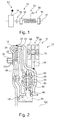
- FIG. 1 shows a block diagram of a torque transmission device 10 in a specific embodiment of the invention.
- the torque transmission device 10 comprises a wet-running clutch device 12 designed as a starting clutch for transmitting a torque between a drive element, for example an internal combustion engine and an output element, for example a transmission.
- the coupling device 12 has a coupling housing 14, in which a fluid can be received.
- a friction device 20 is introduced for selectively effecting or interrupting the torque transmission between the drive element and output element.
- the friction device 20 is connected downstream of a torsional vibration damper 50 with respect to the torque transmission path, which has a damper input part 52 and a damper output part 56 rotatable relative to the latter against the action of energy storage elements 54.
- the damper output part 56 is connectable to an output member 44.
- a damping device 60 is arranged in front of the friction device 12.
- the absorber device 60 is arranged on the clutch housing 14.
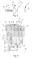
- FIG. 3 is a cross-sectional view of a portion of a torque transmitting device 10 in a particular embodiment of the invention.
- Component of the torque transmission device 10 forms a rotatable about an axis of rotation 100 wet-running and designed as a starting clutch coupling means 12 which is enclosed by a two-part clutch housing 14, wherein a fluid is received.
- the clutch housing 14 is connectable to a driver element 16 with a drive element.
- the driver element 16 is attached to the clutch housing 14, in particular welded or riveted.
- a friction device 20 is arranged, which can detachably connect a clutch input part 22 with a clutch output part 28 via the action of friction regions 30.
- the clutch input part 22 is designed as part of the clutch housing 14. Effective between the clutch input part 22 and the coupling output part 28, an intermediate element 24 is introduced, the housing side via a first Friction region 30 and opposite via a second friction portion 30 with a piston member 36 is connectable.
- the piston member 36 is axially slidably received on an output hub 44 and rotatably connected to the clutch housing 14, in particular riveted.
- the intermediate member 24 is rotatably connected to the clutch output member 28 via a toothing.
- the clutch output part 28 is integrally formed with a damper input part 52 of the friction device 20 downstream torsional vibration damper 50 and received centered on the output hub 44.
- the damper input part 52 is supplemented by a further component 58, which is fixedly connected to the damper input part 52.
- the damper input part 52 serves to act on energy storage elements 54 for transmitting a torque to a relative to the damper input part 52 limited rotatable damper output member 56, to which the damper output member 56 is in engagement with the energy storage elements 54.
- the damper output part 56 is integrally formed with the output hub 44, which has radially inwardly a toothing for the rotationally fixed connection to an output shaft.
- the output hub is supported via a bearing element 46 and a further bearing element 48 on the clutch housing 14, in particular axially supported on both sides.
- an absorber device 60 is mounted rotatably outside of the clutch housing 14.
- the absorber device 60 is designed as a centrifugal pendulum device, comprising a pendulum mass carrier 64 which is fixedly connected to the clutch housing 14, in particular welded.
- the pendulum mass carrier 64 extends from the connection point radially outward and takes in a radially outer region axially on both sides pendulum masses 68, which are connected to each other via spacer bolts 70.
- the spacing bolts 70 engage through corresponding cutouts in the pendulum mass carrier 64.
- the pendulum masses 68 are limited in displacement in the pendulum mass carrier 64 rolling elements relative to the pendulum mass carrier 64 along a pendulum track. As a result, a speed-dependent eradication of torsional vibrations can be effected.
- FIG. 3 shows a block diagram of a torque transmission device 10 in a further specific embodiment of the invention.
- the torque transmission device 10 comprises a wet-running clutch device 12 designed as a starting clutch for transmitting a torque between a drive element, for example an internal combustion engine and an output element, for example a transmission.
- the coupling device 12 has a coupling housing 14, in which a fluid can be received.
- a friction device 20 is introduced for selectively effecting or interrupting the torque transmission between the drive element and output element.
- the friction device 20 is preceded by a torsional vibration damper 50 in relation to the torque transmission path, which has a damper input part 52 and a damper output part 56 rotatable in a limited manner against the action of energy storage elements 54.
- the damper output part 56 is connected to the clutch housing 14, in particular rotatably connected, preferably designed in one piece with this.
- the torsional vibration damper 50 is disposed outside of the clutch housing 14.
- a damping device 60 is arranged in front of the friction device 12.
- the absorber device 60 is arranged on the clutch housing 14.
- a further absorber device 60 is arranged on an output component, in particular the output hub 44. In this case, this absorber 60 may be mounted inside or outside of the coupling housing 14.
- FIG. 4 is a cross section of a section of a torque transmission device 10 is shown in a further specific embodiment of the invention.
- Component of the torque transmission device 10 forms a rotatable about an axis of rotation 100 wet-running and designed as a starting clutch coupling means 12 which is enclosed by a two-part clutch housing 14, wherein a fluid is received.
- the clutch housing 14 is connectable via a torsional vibration damper 72 with a drive element.
- the torsional vibration damper 72 has a damper input part 74, which can be connected to a drive element, for example via a toothing, and is in engagement with energy storage elements 76.
- a damper output member 78 is operatively connectable to the energy storage elements 76 for transmission of torque between the damper input part 74 and the damper output part 78, for which purpose the damper output part 78 is limitedly rotatable relative to the damper input part 74.
- the damper output part 78 is in particular formed integrally with the clutch housing 14 and surrounds the energy storage elements 76 radially outward.
- projections 80 for torque transmission between energy storage elements 76 and damper output member 78 are projections 80, in particular tabs formed from the clutch housing 14, which are effectively engaged with the energy storage elements 76.
- the clutch housing 14 receives in the interior a friction device 20, which can connect a clutch input part 22 with a clutch output part 28 via the action of friction regions 30 releasably.
- the clutch input part 22 is designed as part of the clutch housing 14. Effective between the clutch input member 22 and the clutch output member 28, an intermediate member 24 is inserted, the housing side via a first friction region 30 and opposite via a second friction region 30 with a piston member 36 is connectable.
- the piston member 36 is axially slidably received on an output hub 44 and rotatably connected to the clutch housing 14, in particular riveted.
- the intermediate element 26 is rotatably connected to the output hub 44 via a toothing.
- the absorber device 60 is designed as a centrifugal pendulum device, comprising a pendulum mass carrier 64, which is fixedly connected to the output hub 44, in particular welded.
- the pendulum mass carrier 64 extends from the connection point radially outward and takes in a radially outer region axially on both sides pendulum masses 68, which are connected to each other via spacer bolts 70.
- the spacing bolts 70 engage through corresponding cutouts in the pendulum mass carrier 64.
- the pendulum masses 70 are limitedly displaceable by means of rolling elements received in the pendulum mass carrier 64 relative to the pendulum mass carrier 64 along a pendulum track. As a result, a speed-dependent eradication of torsional vibrations can be effected.
- the absorber device 60 is connected downstream of the friction device with respect to the torque transmission path.
- Another, second Tilger noticed 62 is upstream of the friction device 20 with respect to the torque transmission path and outside and fixedly connected to the clutch housing 14, in particular riveted.
- the absorber 62 is designed as a centrifugal pendulum device.
- the absorber 62 is arranged on the output side with respect to the coupling housing.
Applications Claiming Priority (1)
| Application Number | Priority Date | Filing Date | Title |
|---|---|---|---|
| DE102012223254 | 2012-12-14 |
Publications (2)
| Publication Number | Publication Date |
|---|---|
| EP2743541A2 true EP2743541A2 (fr) | 2014-06-18 |
| EP2743541A3 EP2743541A3 (fr) | 2018-01-03 |
Family
ID=49766929
Family Applications (1)
| Application Number | Title | Priority Date | Filing Date |
|---|---|---|---|
| EP13196669.9A Withdrawn EP2743541A3 (fr) | 2012-12-14 | 2013-12-11 | Dispositif de transmission de couple |
Country Status (2)
| Country | Link |
|---|---|
| EP (1) | EP2743541A3 (fr) |
| DE (1) | DE102013225599A1 (fr) |
Cited By (3)
| Publication number | Priority date | Publication date | Assignee | Title |
|---|---|---|---|---|
| US20150240912A1 (en) * | 2012-07-06 | 2015-08-27 | Schaeffler Technologies Gmbh & Co. Kg | Centrifugal pendulum device for vibration isolation |
| FR3033858A1 (fr) * | 2015-03-16 | 2016-09-23 | Valeo Embrayages | Dispositif d'amortissement d'oscillations de torsion pour systeme de transmission de vehicule |
| WO2018134011A1 (fr) * | 2017-01-18 | 2018-07-26 | Zf Friedrichshafen Ag | Ensemble de transmission de couple |
Families Citing this family (2)
| Publication number | Priority date | Publication date | Assignee | Title |
|---|---|---|---|---|
| DE102016202980A1 (de) | 2016-02-25 | 2017-08-31 | Schaeffler Technologies AG & Co. KG | Antriebsstrang mit einem hydrodynamischen Drehmomentwandler und Fliehkraftpendel sowie hydrodynamischer Drehmomentwandler |
| DE102019200210A1 (de) * | 2019-01-10 | 2020-07-16 | Zf Friedrichshafen Ag | Kupplungsanordnung |
Family Cites Families (5)
| Publication number | Priority date | Publication date | Assignee | Title |
|---|---|---|---|---|
| DE102006028552A1 (de) * | 2005-10-29 | 2007-05-03 | Luk Lamellen Und Kupplungsbau Beteiligungs Kg | Kupplungseinrichtung |
| DE102008042466A1 (de) | 2008-09-30 | 2010-04-01 | Zf Friedrichshafen Ag | Nasslaufende Anfahrkupplung |
| DE102009042836A1 (de) * | 2008-11-24 | 2010-05-27 | Luk Lamellen Und Kupplungsbau Beteiligungs Kg | Fliehkraftpendel |
| DE102010018774B4 (de) * | 2009-05-06 | 2020-06-18 | Schaeffler Technologies AG & Co. KG | Doppelkupplung mit Drehschwingungsdämpfer |
| DE102010049930A1 (de) * | 2009-11-19 | 2011-05-26 | Schaeffler Technologies Gmbh & Co. Kg | Drehmomentübertragungseinrichtung |
-
2013
- 2013-12-11 EP EP13196669.9A patent/EP2743541A3/fr not_active Withdrawn
- 2013-12-11 DE DE102013225599.3A patent/DE102013225599A1/de not_active Ceased
Cited By (6)
| Publication number | Priority date | Publication date | Assignee | Title |
|---|---|---|---|---|
| US20150240912A1 (en) * | 2012-07-06 | 2015-08-27 | Schaeffler Technologies Gmbh & Co. Kg | Centrifugal pendulum device for vibration isolation |
| US9689462B2 (en) * | 2012-07-06 | 2017-06-27 | Schaeffler Technologies AG & Co. KG | Centrifugal pendulum device for vibration isolation |
| FR3033858A1 (fr) * | 2015-03-16 | 2016-09-23 | Valeo Embrayages | Dispositif d'amortissement d'oscillations de torsion pour systeme de transmission de vehicule |
| EP3073147A1 (fr) * | 2015-03-16 | 2016-09-28 | Valeo Embrayages | Dispositif d'amortissement d'oscillations de torsion pour systeme de transmission de vehicule |
| WO2018134011A1 (fr) * | 2017-01-18 | 2018-07-26 | Zf Friedrichshafen Ag | Ensemble de transmission de couple |
| US11047461B2 (en) | 2017-01-18 | 2021-06-29 | Zf Friedrichshafen Ag | Torque transmission assembly |
Also Published As
| Publication number | Publication date |
|---|---|
| EP2743541A3 (fr) | 2018-01-03 |
| DE102013225599A1 (de) | 2014-06-18 |
Similar Documents
| Publication | Publication Date | Title |
|---|---|---|
| DE112011100547B4 (de) | Drehmomentübertragungseinrichtung | |
| DE102010014674B4 (de) | Hydrodynamischer Drehmomentwandler | |
| DE112011100549B4 (de) | Hydrodynamischer Drehmomentwandler | |
| DE112009001368B4 (de) | Drehschwingungsdämpfer mit Fliehkraftpendel | |
| DE112011100546B4 (de) | Hydrodynamischer Drehmomentwandler | |
| EP2724050B1 (fr) | Dispositif de transmission de couple de rotation | |
| DE102012219799B4 (de) | Drehmomentübertragungseinrichtung | |
| DE102012212970A1 (de) | Drehmomentübertragungseinrichtung und Antriebsstrang mit Drehmomentübertragungseinrichtung | |
| EP2706262A2 (fr) | Dispositif de transmission de couple | |
| DE102010025582A1 (de) | Drehmomentübertragungseinrichtung | |
| EP2706260B1 (fr) | Dispositif de transmission de couple | |
| EP2743541A2 (fr) | Dispositif de transmission de couple | |
| DE102014214634A1 (de) | Rotationsbaugruppe für eine Kupplung und/oder Dämpfereinrichtung sowie Drehmomentübertragungseinrichtung | |
| DE102012219965B4 (de) | Torsionsschwingungsdämpfer | |
| DE102011084641A1 (de) | Drehmomentübertragungseinrichtung | |
| EP2706263B1 (fr) | Dispositif de transmission de couple | |
| WO2016150441A1 (fr) | Dispositif de transmission de couple | |
| DE102008057104B4 (de) | Kraftübertragungsvorrichtung und Verfahren zur Montage einer Dämpferanordnung in einer Kraftübertragungsvorrichtung | |
| EP2706261A2 (fr) | Dispositif de transmission de couple | |
| DE102014220901A1 (de) | Baueinheit einer Kopplungsanordnung mit einer Schwingungsreduzierungseinrichtung und mit einer Kupplungseinrichtung | |
| WO2014023306A1 (fr) | Dispositif de pendule à force centrifuge | |
| EP3593007B1 (fr) | Système d'amortissement | |
| DE102013220417A1 (de) | Dämpfervorrichtung für einen Antriebsstrang eines Kraftfahrzeugs | |
| DE102012219194A1 (de) | Torsionsschwingungsdämpferanordnung | |
| DE102016214679A1 (de) | Drehschwingungsreduzierung |
Legal Events
| Date | Code | Title | Description |
|---|---|---|---|
| PUAI | Public reference made under article 153(3) epc to a published international application that has entered the european phase |
Free format text: ORIGINAL CODE: 0009012 |
|
| 17P | Request for examination filed |
Effective date: 20131211 |
|
| AK | Designated contracting states |
Kind code of ref document: A2 Designated state(s): AL AT BE BG CH CY CZ DE DK EE ES FI FR GB GR HR HU IE IS IT LI LT LU LV MC MK MT NL NO PL PT RO RS SE SI SK SM TR |
|
| AX | Request for extension of the european patent |
Extension state: BA ME |
|
| RAP1 | Party data changed (applicant data changed or rights of an application transferred) |
Owner name: SCHAEFFLER TECHNOLOGIES AG & CO. KG |
|
| PUAL | Search report despatched |
Free format text: ORIGINAL CODE: 0009013 |
|
| AK | Designated contracting states |
Kind code of ref document: A3 Designated state(s): AL AT BE BG CH CY CZ DE DK EE ES FI FR GB GR HR HU IE IS IT LI LT LU LV MC MK MT NL NO PL PT RO RS SE SI SK SM TR |
|
| AX | Request for extension of the european patent |
Extension state: BA ME |
|
| RIC1 | Information provided on ipc code assigned before grant |
Ipc: F16F 15/139 20060101AFI20171128BHEP Ipc: F16F 15/14 20060101ALI20171128BHEP |
|
| STAA | Information on the status of an ep patent application or granted ep patent |
Free format text: STATUS: THE APPLICATION IS DEEMED TO BE WITHDRAWN |
|
| 18D | Application deemed to be withdrawn |
Effective date: 20180704 |
|
| P01 | Opt-out of the competence of the unified patent court (upc) registered |
Effective date: 20230522 |