EP1908962A2 - Dispositif d'étanchéité pour machine à fluide - Google Patents
Dispositif d'étanchéité pour machine à fluide Download PDFInfo
- Publication number
- EP1908962A2 EP1908962A2 EP07018756A EP07018756A EP1908962A2 EP 1908962 A2 EP1908962 A2 EP 1908962A2 EP 07018756 A EP07018756 A EP 07018756A EP 07018756 A EP07018756 A EP 07018756A EP 1908962 A2 EP1908962 A2 EP 1908962A2
- Authority
- EP
- European Patent Office
- Prior art keywords
- ring
- sealing
- sliding contact
- contact surface
- scroll
- Prior art date
- Legal status (The legal status is an assumption and is not a legal conclusion. Google has not performed a legal analysis and makes no representation as to the accuracy of the status listed.)
- Withdrawn
Links
- 238000007789 sealing Methods 0.000 title claims abstract description 117
- 239000012530 fluid Substances 0.000 title claims abstract description 50
- 239000013013 elastic material Substances 0.000 claims abstract description 11
- 238000010276 construction Methods 0.000 description 22
- 230000015556 catabolic process Effects 0.000 description 12
- 238000006731 degradation reaction Methods 0.000 description 12
- 230000006866 deterioration Effects 0.000 description 4
- 230000002035 prolonged effect Effects 0.000 description 3
- 230000003247 decreasing effect Effects 0.000 description 2
- 238000005516 engineering process Methods 0.000 description 2
- 239000000463 material Substances 0.000 description 2
- 238000000034 method Methods 0.000 description 1
- 238000013021 overheating Methods 0.000 description 1
- 230000002093 peripheral effect Effects 0.000 description 1
Images
Classifications
-
- F—MECHANICAL ENGINEERING; LIGHTING; HEATING; WEAPONS; BLASTING
- F04—POSITIVE - DISPLACEMENT MACHINES FOR LIQUIDS; PUMPS FOR LIQUIDS OR ELASTIC FLUIDS
- F04C—ROTARY-PISTON, OR OSCILLATING-PISTON, POSITIVE-DISPLACEMENT MACHINES FOR LIQUIDS; ROTARY-PISTON, OR OSCILLATING-PISTON, POSITIVE-DISPLACEMENT PUMPS
- F04C18/00—Rotary-piston pumps specially adapted for elastic fluids
- F04C18/02—Rotary-piston pumps specially adapted for elastic fluids of arcuate-engagement type, i.e. with circular translatory movement of co-operating members, each member having the same number of teeth or tooth-equivalents
- F04C18/0207—Rotary-piston pumps specially adapted for elastic fluids of arcuate-engagement type, i.e. with circular translatory movement of co-operating members, each member having the same number of teeth or tooth-equivalents both members having co-operating elements in spiral form
- F04C18/0215—Rotary-piston pumps specially adapted for elastic fluids of arcuate-engagement type, i.e. with circular translatory movement of co-operating members, each member having the same number of teeth or tooth-equivalents both members having co-operating elements in spiral form where only one member is moving
-
- F—MECHANICAL ENGINEERING; LIGHTING; HEATING; WEAPONS; BLASTING
- F01—MACHINES OR ENGINES IN GENERAL; ENGINE PLANTS IN GENERAL; STEAM ENGINES
- F01C—ROTARY-PISTON OR OSCILLATING-PISTON MACHINES OR ENGINES
- F01C19/00—Sealing arrangements in rotary-piston machines or engines
- F01C19/005—Structure and composition of sealing elements such as sealing strips, sealing rings and the like; Coating of these elements
-
- F—MECHANICAL ENGINEERING; LIGHTING; HEATING; WEAPONS; BLASTING
- F04—POSITIVE - DISPLACEMENT MACHINES FOR LIQUIDS; PUMPS FOR LIQUIDS OR ELASTIC FLUIDS
- F04C—ROTARY-PISTON, OR OSCILLATING-PISTON, POSITIVE-DISPLACEMENT MACHINES FOR LIQUIDS; ROTARY-PISTON, OR OSCILLATING-PISTON, POSITIVE-DISPLACEMENT PUMPS
- F04C27/00—Sealing arrangements in rotary-piston pumps specially adapted for elastic fluids
- F04C27/005—Axial sealings for working fluid
Definitions
- the present invention relates to a sealing device of fluid machinery having a stationary member, an orbiting member, an end surface of which slides on an inner face of the stationary member, and a sealing member to be fitted into a sealing groove engraved on the end surface along the ridge line of the end surface, a sliding contact surface of the sealing member being pressed onto an inner surface of the stationary member with a predetermined force to slide on the inner surface in order that fluid sealing is secured between the sliding contact surface of the sealing member and the inner surface of the stationary member.
- volumetric efficiencies thereof vary greatly depending on a sealing function of a working fluid between an end plate of the stationary scroll and an end surface of an orbiting scroll provided so as to revolve against the stationary scroll. Consequently, many technologies have been proposed regarding a tip seal construction between the end plate of the stationary scroll and the end surface of the orbiting scroll.
- a fluid seal between the end plate of the stationary scroll and the end surface of the orbiting scroll is secured by a construction that a sealing groove is engraved on the end surface along the ridge line of the end surface, for receiving a tip seal member fitted into the sealing groove, a sliding contact surface of the tip seal member is pressed onto an inner surface of the end plate of the stationary scroll with a predetermined force to slide on the inner surface of the end plate of the stationary scroll at the sliding contact surface.
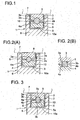
- FIG. 4 is a perspective view of an orbiting scroll of the scroll type fluid machine.
- the reference numeral 1 shows an orbiting scroll which moves on an inner surface of an end plate 7 (See Fig. 5) of a stationary scroll (not shown).
- a lap 6 of a spiral wall shape is set-up on a base plate 6a of the orbiting scroll 1.
- a sealing groove 10 is engraved on the wall end surface, namely, an end surface of the lap 6 along the ridge line of the end surface of the orbiting scroll 1, and a tip seal member 2 is fitted into the sealing groove 10.
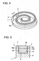
- Fig. 5 shows an example of conventional tip seal construction of the above described orbiting scroll 1.
- reference numeral, 6 shows a lap of the orbiting scroll 1
- 7 is an end plate composing the stationary member, and 10 a sealing groove engraved on the end surface of the lap 6 along the ridge line of the tip end surface of the orbiting scroll 1.
- the numeral 02s shows a tip seal assembly to be fitted into the sealing groove 10, and the assembly is composed of a tip seal member 02 and a back-up ring 05.
- a sliding contact surface 08 of an end surface of the tip seal member 02 slides on the end plate 7, and the back-up ring 05 is made of spring materials and placed inside the tip seal member 02.
- the sliding contact surface 08 is pressed onto the inner surface of the end plate 7 by a spring force of the back-up ring 05 and a pressure force of fluid introduced into a clearance 9 inside the back-up ring 05.
- fluid sealing is secured between the sliding contact surface 08 of the tip seal 02 and the inner surface of the end plate 7.
- patent literature 1 JP: 1998-214977,A discloses a tip sealing construction having a stationary scroll, an orbiting scroll moving along the inner surface of an end plate of the stationary scroll, and a sealing member to be fitted into a sealing groove engraved on the end surface along the ridge line of the end surface, a sliding contact surface of the sealing member being pressed onto an inner surface of the end plate with a predetermined force to slide on the inner surface in order that fluid sealing is secured between the sliding contact surface of the tip sealing member and the inner surface of the end plate.
- the tip seal member is formed by fitting a back-up member, which is a spring member having a C-shaped cross section, into an outer seal of C-shape cross section which contacts to slide on the inner surface of an end plate, and further fitting an O-ring inside the back-up member, thereby the elasticity of the O-ring and the back-up member of C-shape cross section presses the outer seal onto the inner surface of the end plate with a predetermined force, while the contact surfaces slide each other.
- a back-up member which is a spring member having a C-shaped cross section
- patent literature 2 JP: 2001-248576,A discloses a tip sealing construction of the scroll type fluid machinery, which is structured such that a seal member is fitted into a sealing groove provided to a lap so as to contact and slide on the inner surface of the end plate, and a rubber back-up ring of hollow circular cross section is placed between the tip seal member and a bottom face of the sealing groove, thereby the elasticity of the back-up ring presses the tip seal member onto the inner surface of the end plate.
- the tip seal member is formed by fitting a back-up member, which is a spring member having a C-shaped cross section, into an outer seal of C-shape cross section which contacts to slide on the inner surface of an end plate, and further fitting an O-ring inside the back-up member, thereby the elasticity of the O-ring and the back-up member of C-shape cross section presses the outer seal onto the inner surface of the end plate with a predetermined force, to slide on the contact surface.
- a back-up member which is a spring member having a C-shaped cross section
- the outer peripheral surface of the outer seal of C-shape cross section is pressed onto the inner surface of the end plate, substantially under a condition of line contact, so that the contact pressure in the contact part becomes high and deteriorates the durability of the outer seal and the contact surface of the outer seal is worn out.
- the seal function between the outer seal and the inner surface of the end plate is lowered, and the volumetric efficiency of the fluid machine is decreased.
- the tip seal member is structured such that a back-up member, which is a spring member having a C-shaped cross section, is fitted inside of an outer seal of C-shape cross section which and an O-ring is fitted inside the back-up member, thereby the elasticity of the O-ring and the back-up member of C-shape cross section presses the outer seal onto the inner surface of the end plate with a predetermined force, to slide on the contact surface, the seal construction is complicated, bringing difficulties such as increased man-hours as to assembling/disassembling the tip seal member.
- a back-up member which is a spring member having a C-shaped cross section
- a purpose of the present invention is to realize an extremely simple seal construction of easy assembling/disassembling, which can prevent the back-up ring from contacting the sealing groove of an orbiting member, thereby the thermal degradation of the back-up ring due to the contact, the lowered seal function of the working fluid, and the decreased volumetric efficiency can be evaded.
- the present invention proposes, for achieving the above-stated purpose, a sealing construction of fluid machinery, including a stationary member, a orbiting member, an end surface of which slides on an inner face of the stationary member, and a sealing member to be fitted into a sealing groove engraved on the end surface along the ridge line of the end surface, a sliding contact surface of the sealing member being pressed onto an inner surface of the stationary member with a predetermined force to slide on the inner surface in order that fluid: sealing is secured between the sliding contact surface of the sealing member and the inner surface of the stationary member, in which the sealing member is divided in a plane parallel to the sliding contact surface into two parts of an upper ring and a lower ring, the upper ring contacting the sliding contact surface and the lower ring facing a bottom surface of the sealing groove, and a back-up ring made from elastic material is provided to be fitted into grooves for the back-up ring, which are engraved on the divided surfaces of the upper ring and the lower ring, in a place not facing the sealing grooves, along
- a sealing device of fluid machinery including a scroll compressor or a scroll vacuum pump, having a stationary scroll, an orbiting scroll, an end surface of which slides on an inner face of the stationary scroll, and a tip seal member to be fitted into a sealing groove engraved on the end surface along the ridge line of the end surface, a sliding contact surface of the tip seal member is pressed onto the inner surface of an end plate of the stationary scroll with a predetermined force to slide on the inner surface in order that fluid sealing is secured between the sliding contact surface of the tip seal member and the inner surface of the end plate of the stationary scroll, in which the tip seal member is divided in a plane parallel to the sliding contact surface into two parts of an upper ring and a lower ring, the upper ring contacting the sliding contact surface and the lower ring facing a bottom surface of the sealing groove, and a back-up ring made from elastic material is provided to be fitted into grooves for the back-
- the cross section of the back-up ring is preferably a circular section, a polygon section, or a cross-shaped section.
- the tip seal member to be fitted into a sealing groove engraved, on the end surface of the orbiting member, along the ridge line of the tip end surface is divided in a plane parallel to the sliding contact surface into two parts of an upper ring contacting the sliding contact surface and a lower ring facing a bottom surface of the sealing groove.
- the tip seal member is fitted into a sealing groove engraved, on the end surface of the orbiting scroll sliding on an inner face of the stationary scroll, along the ridge line of the end surface is divided in a plane parallel to the sliding contact surface into two parts of an upper ring and a lower ring, the upper ring contacting the sliding contact surface and the lower ring facing a bottom surface of the sealing groove.
- a back-up ring made from elastic material is provided to be fitted into grooves for the back-up ring, which are engraved on the divided surfaces of the upper ring and the lower ring, in a place not facing the sealing grooves, along the longitudinal direction of the sliding contact surface.
- the present invention makes it possible to secure a fluid seal between the sliding contact surface and the inner face of the end plate by pressing the sliding contact surface of the upper ring 3 onto the inner face of the stationary member (the end plate) by means of a pressure of a working fluid which flows into a clearance between the sealing groove and the tip seal member as well as by means of an elasticity of the back-up ring made from elastic material.
- a back-up ring is fitted into grooves for the back-up ring, which are engraved on the divided surfaces of the upper ring and the lower ring, in a place not facing the sealing grooves, along the longitudinal direction of the sliding contact surface, so that the back-up ring does not touch the orbiting member. Therefore, even when the orbiting member such as the orbiting scroll in scroll type compressors or scroll type vacuum pumps is operated at high temperature, a heat transfer from the orbiting member to the back-up ring is restrained and a thermal degradation of the back-up ring caused due to the heating-up by the heat transfer can be prevented.
- the durability of the back-up ring is improved as a result of preventing the thermal degradation caused by the contact between the back-up ring and the inner face of the stationary member. Further it can be evaded for the sealing function of the back-up ring to be deteriorated by the thermal degradation, the sealing function being a back-up function for pressing the sliding contact surface of the upper ring 3 onto the inner surface of the stationary member (the end plate). In this way, even when the orbiting scroll is in.operation at elevated temperature, a fluid seal condition between the sliding contact surface and the inner surface of the end plate is always maintained securely. As a result, a high volumetric efficiency is maintained.
- the cross section can be a polygon section, or a cross-shaped section.
- the back-up ring can be stably fitted into the sealing groove without sliding on the grooves of the upper/lower ring in rotational direction (in twisted direction), because of the flat side part of the back-up ring along the longitudinal direction,
- the sealing member or the tip sealing member is constructed such that the cross sections of the upper-ring and the lower-ring are of the same shape and the upper-ring, the lower-ring, and the back-up ring are assembled and/or disassembled separately.
- the shape of the cross section of the upper ring is the same as that of the lower ring and each of the upper ring, the lower ring, and the back-up ring is separately assembled into or disassembled from the sealing groove. Therefore, the upper ring and the lower ring are inter-changeable. To be more specifically, the upper ring and the lower ring for the lap of the orbiting member are inter-changeable with the lower ring and the upper ring for the lap of the stationary member respectively.
- the lower ring When the sliding contact surface of the upper ring is worn out, the lower ring can be, with up side down, mounted in the space of the upper ring so that the upper surface (a surface facing the bottom of the sealing groove) of the lower ring becomes a substitute for the sliding contact surface which is pressed onto the inner surface of the stationary member (the end plate), so that the lower ring is reusable.
- the upper ring, the lower ring, and the back-up ring for the orbiting member are reusable as the lower ring, the upper ring, and the back-up ring for the stationary member respectively.
- the upper ring, the lower ring, and the back-up ring installed in the orbiting member which are less sensitive to thermal degradation, are reusable. After all, a lifetime of the back-up ring can be prolonged.
- the tip seal member to be fitted into a sealing groove engraved, on the end surface of the orbiting scroll sliding on the stationary member such as end plate, along the ridge line of the tip end surface is divided in a plane parallel to the sliding contact surface into two parts of an upper ring and a lower ring, the upper ring contacting the sliding contact surface and the lower ring facing a bottom surface of the sealing groove, and further grooves for back-up ring into which a back-up ring made from elastic material is fitted are engraved on the divided surfaces of the upper ring and the lower ring, in a place not facing the sealing grooves, along the longitudinal direction of the sliding contact surface.
- the sliding contact surface of the upper ring is pressed onto the inner face of the stationary member (the end plate) by means of a pressure of a working fluid flowing into a clearance between the sealing groove and the sealing member as well as by means of an elasticity of the back-up ring made from elastic material, to secure a fluid seal between the sliding contact surface and the inner face of the end plate.
- the shape of the cross section of the upper ring is the same as that of the lower ring, and each of the upper ring, the lower ring, and the back-up ring is separately assembled into or disassembled from the sealing groove, accordingly the upper ring and the lower ring are inter-changeable.
- the lower ring can be,'with up side down, mounted in the space of the upper ring so that the upper surface (a surface facing the bottom of the sealing groove) of the lower ring becomes a substitute for the sliding contact surface which is pressed onto the inner surface of the stationary member (the end plate).
- the lower ring is reusable.
- a lifetime of the back-up ring can be prolonged, and the time between replacement of the upper ring and the lower ring can be extended.
- the' present invention provides a sealing construction of a fluid machinery with an extremely simple seal construction, in which the sealing member is divided into two parts of an upper ring and a lower ring, the upper ring contacting the sliding contact surface and the lower ring facing a bottom surface of the sealing groove and grooves for fitting a back-up ring are engraved on the divided surfaces of the upper ring and the lower ring.
- the present invention realizes, with such extremely simple seal construction of less assembling and disassembling process, a sealing device of fluid machinery, which can evade a back-up ring contacting a sealing groove, thereby deterioration due to thermal degradation is lessened and deterioration of the sealing function and/or the volumetric efficiency is prevented.
- FIG. 4 is a perspective view regarding an orbiting scroll of a scroll type fluid machine as an application example of the present invention.
- the reference numeral 1 shows an orbiting scroll which moves along an inner surface of an end plate 7 (See Fig. 1) of a stationary scroll (not shown).
- a lap 6 of a spiral wall shape is set-up on a base plate 6a of the orbiting scroll 1
- a sealing groove 10 is engraved on the wall end surface, namely, an end surface of the lap 6 along the ridge line of the end surface of the orbiting scroll 1
- a tip seal 2 is fitted into the sealing groove.
- the present invention relates to a fluid seal construction applicable for scroll-type fluid machines between a sliding surface of sealing members (tip seal elements) and an inner surface of stationary member.
- FIG.1 is a partial cross section (A-A cross section in Fig. 4) showing a tip seal construction of a scroll type fluid machine relating to a first embodiment of the present invention.
- reference numeral 6 shows a lap of the orbiting scroll
- 7 is an end plate composing the stationary member
- 10 is a sealing groove engraved on the tip end surface of the lap 6 along the ridge line of the tip end surface of the orbiting scroll 1.
- the reference numeral 2 shows a tip seal member comprising of an upper ring 3, which forms a sliding contact surface 8 on the inner surface of the end plate 7, and a lower ring 4, the lower side of which faces a bottom surface 10a of the sealing groove 10.
- the tip seal member is divided in a plane parallel to the sliding contact surface 8 into two parts of the upper ring 3 and the lower ring 4.
- the reference numerals 3a and 4a show engraved grooves for receiving a back-up ring (grooves for a back-up ring 5).
- the grooves 3a and 4a are engraved on the divided surfaces of the upper ring 3 and the lower ring 4 respectively so that the grooves for the back-up ring do not face to the sealing groove and are located inside, namely in the central part of the seal member.
- the reference numeral 5 shows the above-mentioned back-up ring which is fitted into the grooves 3a and 4a.
- a tip seal member 2 is fitted into the sealing groove 10 engraved on the end surface of the lap, along the ridge line of the end surface of the orbiting scroll 1 which slides on an inner face of the end plate 7.
- the tip seal member 2 is divided in a plane parallel to the sliding contact surface 8 into two parts of an upper ring 3 and a lower ring 4, in which the upper ring 3 serves to form the sliding contact surface 8 and the lower ring 4 faces a bottom surface of the sealing groove 10; wherein grooves 3a and 4a for a back-up ring 5 are engraved on the divided surfaces 3b and 4b of the upper ring 3 and the lower ring 4 so that the grooves 3a and 4a for the back-up ring 5 do not face to the sealing groove 10, being engraved along the longitudinal direction of the sliding contact surface 8, and the back-up ring made from elastic material is fitted into the grooves 3a and 4a for the back-up ring.
- the sliding contact surface 8 of the upper ring 3 is pressed onto the inner face of the end plate 7 by means of a pressure of a working fluid which flows into a clearance 9 between the sealing groove 10 and the tip seal member 2 as well as by means of an elasticity of the back-up ring 5 made from elastic material, thereby it is possible to secure a fluid seal between the sliding contact surface 8 and the inner face of the end plate 7
- the back-up ring 5 is fitted into the grooves 3a and 4a which are engraved on the divided surfaces of the upper ring 3 and the lower ring 4 in the central part of the seal member so as not to face to the sealing groove 10. Since the back-up ring 5 are not in contact with the lap 6 of the orbiting scroll 1, even when the temperature of the lap 6 is raised during operation, a heat transfer from the lap 6 to the back-up ring 5 is restrained. As a result, it is possible to prevent a thermal degradation of the back-up ring 5 caused by the heating-up by the heat transfer.
- the durability of the back-up ring 5 is improved, it can be evaded for the buck-up function of the back-up ring 5 for pressing the sliding contact surface 8 of the upper ring 3 onto the inner surface of the end plate 7 to be deteriorated by the thermal degradation.
- a fluid seal condition between the sliding contact surface and the inner surface of the end plate is always maintained securely, and a high volumetric efficiency is maintained.
- the shape of the cross section of the upper ring 3 is the same as that of the lower ring 4, and moreover each of the upper ring 3, the lower ring 4, and the back-up ring 5 is separately mountable into or dismountable from the sealing groove 10. Therefore, the upper ring 3 and the lower ring 4 are inter-changeable. More exactly, the upper ring and the lower ring for the lap of the orbiting scroll are inter-changeable to the lower ring and the upper ring for the lap of the stationary scroll respectively.
- the lower ring 4 can be, with up side down, mounted in the space of the upper ring 3 so that the upper surface (a surface facing the bottom of the sealing groove 10) of the lower ring 4 becomes a substitute for the sliding contact surface 8 which is pressed onto the inner surface of the end plate 7.
- the lower ring 4 is reusable.
- the upper ring 3, the lower ring 4, and the back-up ring 5 for the orbiting scroll are reusable as the lower ring 4, the upper ring 3, and the back-up ring 5 for the stationary scroll respectively.
- the upper ring 3, the lower ring 4, and the back-up ring 5 installed in the orbiting scroll which are less sensitive to thermal degradation, are reusable. After all, a lifetime of the back-up ring 5 can be prolonged.
- FIG. 2(A) and FIG. 2(B) illustrate a second embodiment of the present invention.
- the cross section of the aforementioned back-up ring is of a square shape with its corners chamfered.
- FIG. 2(A) the corners of the cross section square are located at up and down sides as well as at right and left sides. Therefore, the back-up ring is fitted into grooves 3a and 4a of a triangle shape.
- FIG. 2(B) the sides of the cross section square are located at up and down sides as well as at right and left sides. Therefore, the back-up ring is fitted into grooves 3a and 4a of a rectangular shape.
- the plane parts of the back up ring 5 and the grooves 3a and 4a for the back-up ring 5 prevent the back-up ring from sliding on the grooves 3a and 4a in rotational direction, therefore the back-up ring 5 can be stably fitted into the sealing groove 10 without relative movements between the upper and lower rings 3 and 4 and the back-up ring.
- FIG. 3 illustrates a third embodiment of the present invention.
- the cross section of the aforementioned back-up ring is of a cross-shaped section wherein a perpendicular part 5y is fitted into grooves 3a and 4a for the back-up ring of square shape, and a flat part 5z is inserted between the divided surfaces 3b and 4b of the upper ring 3 and the lower ring 4.
- the back-up ring 5 owing to the sides of the perpendicular part 5y of the back-up ring 5, the flat part 5z of the back-up' ring 5, the plane surfaces of the grooves 3a/4a for the back-up ring 5, the back-up ring is prevented from sliding on the grooves 3a and 4a in rotational direction. Therefore, the back-up ring 5 can be stably fitted into the sealing groove 10 without relative movements between the upper and lower rings 3 and 4 and the back-up ring.
- the present invention provides a sealing device for fluid machinery, with an extremely simple construction for assembling and disassembling, which can evade a contact of a back-up ring onto a sealing groove of a orbiting member. Therefore, deterioration of the back-up ring due to thermal degradation caused by the contact can be prevented, and resulting deterioration of the sealing function and/or the volumetric efficiency is lessened.
Landscapes
- Engineering & Computer Science (AREA)
- Mechanical Engineering (AREA)
- General Engineering & Computer Science (AREA)
- Rotary Pumps (AREA)
Applications Claiming Priority (1)
| Application Number | Priority Date | Filing Date | Title |
|---|---|---|---|
| JP2006261638A JP4873706B2 (ja) | 2006-09-27 | 2006-09-27 | 流体機械のシール構造 |
Publications (1)
| Publication Number | Publication Date |
|---|---|
| EP1908962A2 true EP1908962A2 (fr) | 2008-04-09 |
Family
ID=38984564
Family Applications (1)
| Application Number | Title | Priority Date | Filing Date |
|---|---|---|---|
| EP07018756A Withdrawn EP1908962A2 (fr) | 2006-09-27 | 2007-09-24 | Dispositif d'étanchéité pour machine à fluide |
Country Status (4)
| Country | Link |
|---|---|
| US (1) | US7491044B2 (fr) |
| EP (1) | EP1908962A2 (fr) |
| JP (1) | JP4873706B2 (fr) |
| CN (1) | CN101153594A (fr) |
Cited By (1)
| Publication number | Priority date | Publication date | Assignee | Title |
|---|---|---|---|---|
| EP3141696A1 (fr) * | 2015-09-10 | 2017-03-15 | Anest Iwata Corporation | Machine de défilement de fluide |
Families Citing this family (6)
| Publication number | Priority date | Publication date | Assignee | Title |
|---|---|---|---|---|
| JP6008568B2 (ja) * | 2012-05-07 | 2016-10-19 | アネスト岩田株式会社 | スクロール流体機械 |
| CN104942543B (zh) * | 2015-06-15 | 2017-03-29 | 中国石油大学(华东) | 上游泵送机械密封的纳米增材制造方法 |
| CN106678468A (zh) * | 2017-02-06 | 2017-05-17 | 江阴市长龄机械制造有限公司 | 大型作业机械回转接头的密封结构 |
| CN108928537A (zh) * | 2017-05-26 | 2018-12-04 | 天津久久辉科技发展有限公司 | 一种水果保鲜盒 |
| US11306719B2 (en) * | 2018-06-18 | 2022-04-19 | Lg Electronics Inc. | Compressor |
| CN111006022B (zh) * | 2019-12-25 | 2021-12-03 | 中科同帜半导体(江苏)有限公司 | 一种液体压差式真空动密封机构 |
Family Cites Families (7)
| Publication number | Priority date | Publication date | Assignee | Title |
|---|---|---|---|---|
| US2456356A (en) * | 1947-12-09 | 1948-12-14 | Joseph S Aber | Packing gasket and static seal |
| US4087099A (en) * | 1976-03-01 | 1978-05-02 | Toyo Kogyo Co., Ltd. | Oil seal means for rotary piston engines |
| US4244588A (en) * | 1979-11-05 | 1981-01-13 | Caterpillar Tractor Co. | Shear seal assembly |
| US5037281A (en) * | 1990-01-08 | 1991-08-06 | Carrier Corporation | Tip seal for scroll compressor |
| US5466134A (en) * | 1994-04-05 | 1995-11-14 | Puritan Bennett Corporation | Scroll compressor having idler cranks and strengthening and heat dissipating ribs |
| JP2000213475A (ja) * | 1999-01-25 | 2000-08-02 | Hitachi Koki Co Ltd | スクロ―ル形真空ポンプ |
| JP3422747B2 (ja) | 2000-03-06 | 2003-06-30 | アネスト岩田株式会社 | スクロール流体機械 |
-
2006
- 2006-09-27 JP JP2006261638A patent/JP4873706B2/ja not_active Expired - Fee Related
-
2007
- 2007-09-24 EP EP07018756A patent/EP1908962A2/fr not_active Withdrawn
- 2007-09-26 US US11/861,743 patent/US7491044B2/en not_active Expired - Fee Related
- 2007-09-27 CN CNA2007101676543A patent/CN101153594A/zh active Pending
Cited By (2)
| Publication number | Priority date | Publication date | Assignee | Title |
|---|---|---|---|---|
| EP3141696A1 (fr) * | 2015-09-10 | 2017-03-15 | Anest Iwata Corporation | Machine de défilement de fluide |
| US10167867B2 (en) | 2015-09-10 | 2019-01-01 | Anest Iwata Corporation | Scroll fluid machine having tip seal member separated into different portions |
Also Published As
| Publication number | Publication date |
|---|---|
| JP2008082213A (ja) | 2008-04-10 |
| CN101153594A (zh) | 2008-04-02 |
| US7491044B2 (en) | 2009-02-17 |
| JP4873706B2 (ja) | 2012-02-08 |
| US20080075614A1 (en) | 2008-03-27 |
Similar Documents
| Publication | Publication Date | Title |
|---|---|---|
| US7491044B2 (en) | Sealing device of fluid machinery | |
| JP6034808B2 (ja) | 往復及び回転用途用のシールアセンブリ | |
| US5588820A (en) | Scroll compressor having an axial compliance pressure chamber | |
| US8684473B2 (en) | Gear pump and gear pump for brake apparatus | |
| EP1271022B1 (fr) | Dispositif de joint à brosses | |
| EP2299149B1 (fr) | Dispositif de garniture mécanique double | |
| US20100201076A1 (en) | Segmented packing ring | |
| WO2008069234A1 (fr) | Système d'emballage et de scellage | |
| CN101529095B (zh) | 涡旋式压缩机 | |
| EP1837563B1 (fr) | Dispositif de joint d'arbre | |
| WO2011030585A1 (fr) | Joint de type à lèvre | |
| CN100380026C (zh) | 密封装置 | |
| JP4704428B2 (ja) | 複合ロータリーシールアセンブリ | |
| EP2484943A1 (fr) | Dispositif d'étanchéité mécanique | |
| JPH1068467A (ja) | シール装置 | |
| EP3196514B1 (fr) | Pompe avec joint d'étanchéité mécanique | |
| EP1193429A1 (fr) | Mecanisme d'etancheite d'arbre de compresseur par joint mecanique | |
| JP5360569B2 (ja) | パッキン | |
| EP2924324B1 (fr) | Joint d'arbre de rotation | |
| US5470215A (en) | Wear resistant vane-type fluid power converter | |
| EP0967392A1 (fr) | Compresseur à spirales avec joint étanche axial à l'huile entre spirale et plaque d'extrémité | |
| JPH06235386A (ja) | スクロール圧縮機 | |
| JP2005240932A (ja) | 密封装置 | |
| EP1757813A1 (fr) | Joint d'extrémité d'un compresseur à volutes | |
| CN112922831A (zh) | 三角转子泵 |
Legal Events
| Date | Code | Title | Description |
|---|---|---|---|
| PUAI | Public reference made under article 153(3) epc to a published international application that has entered the european phase |
Free format text: ORIGINAL CODE: 0009012 |
|
| AK | Designated contracting states |
Kind code of ref document: A2 Designated state(s): AT BE BG CH CY CZ DE DK EE ES FI FR GB GR HU IE IS IT LI LT LU LV MC MT NL PL PT RO SE SI SK TR |
|
| AX | Request for extension of the european patent |
Extension state: AL BA HR MK RS |
|
| STAA | Information on the status of an ep patent application or granted ep patent |
Free format text: STATUS: THE APPLICATION HAS BEEN WITHDRAWN |
|
| 18W | Application withdrawn |
Effective date: 20110624 |