EP1908902A2 - Dispositif de verrouillage à un point en particulier pour des armoires électriques - Google Patents
Dispositif de verrouillage à un point en particulier pour des armoires électriques Download PDFInfo
- Publication number
- EP1908902A2 EP1908902A2 EP07017522A EP07017522A EP1908902A2 EP 1908902 A2 EP1908902 A2 EP 1908902A2 EP 07017522 A EP07017522 A EP 07017522A EP 07017522 A EP07017522 A EP 07017522A EP 1908902 A2 EP1908902 A2 EP 1908902A2
- Authority
- EP
- European Patent Office
- Prior art keywords
- latch
- locking
- spring
- closing
- locking pin
- Prior art date
- Legal status (The legal status is an assumption and is not a legal conclusion. Google has not performed a legal analysis and makes no representation as to the accuracy of the status listed.)
- Withdrawn
Links
- 230000000903 blocking effect Effects 0.000 claims description 16
- 238000011161 development Methods 0.000 description 1
- 230000018109 developmental process Effects 0.000 description 1
- 230000000694 effects Effects 0.000 description 1
Images

Classifications
-
- E—FIXED CONSTRUCTIONS
- E05—LOCKS; KEYS; WINDOW OR DOOR FITTINGS; SAFES
- E05C—BOLTS OR FASTENING DEVICES FOR WINGS, SPECIALLY FOR DOORS OR WINDOWS
- E05C3/00—Fastening devices with bolts moving pivotally or rotatively
- E05C3/12—Fastening devices with bolts moving pivotally or rotatively with latching action
- E05C3/16—Fastening devices with bolts moving pivotally or rotatively with latching action with operating handle or equivalent member moving otherwise than rigidly with the latch
- E05C3/22—Fastening devices with bolts moving pivotally or rotatively with latching action with operating handle or equivalent member moving otherwise than rigidly with the latch the bolt being spring controlled
- E05C3/24—Fastening devices with bolts moving pivotally or rotatively with latching action with operating handle or equivalent member moving otherwise than rigidly with the latch the bolt being spring controlled in the form of a bifurcated member
-
- E—FIXED CONSTRUCTIONS
- E05—LOCKS; KEYS; WINDOW OR DOOR FITTINGS; SAFES
- E05B—LOCKS; ACCESSORIES THEREFOR; HANDCUFFS
- E05B47/00—Operating or controlling locks or other fastening devices by electric or magnetic means
- E05B47/0001—Operating or controlling locks or other fastening devices by electric or magnetic means with electric actuators; Constructional features thereof
- E05B47/0002—Operating or controlling locks or other fastening devices by electric or magnetic means with electric actuators; Constructional features thereof with electromagnets
-
- E—FIXED CONSTRUCTIONS
- E05—LOCKS; KEYS; WINDOW OR DOOR FITTINGS; SAFES
- E05B—LOCKS; ACCESSORIES THEREFOR; HANDCUFFS
- E05B47/00—Operating or controlling locks or other fastening devices by electric or magnetic means
- E05B47/06—Controlling mechanically-operated bolts by electro-magnetically-operated detents
- E05B47/0607—Controlling mechanically-operated bolts by electro-magnetically-operated detents the detent moving pivotally or rotatively
-
- E—FIXED CONSTRUCTIONS
- E05—LOCKS; KEYS; WINDOW OR DOOR FITTINGS; SAFES
- E05B—LOCKS; ACCESSORIES THEREFOR; HANDCUFFS
- E05B47/00—Operating or controlling locks or other fastening devices by electric or magnetic means
- E05B2047/0048—Circuits, feeding, monitoring
- E05B2047/0067—Monitoring
- E05B2047/0069—Monitoring bolt position
-
- E—FIXED CONSTRUCTIONS
- E05—LOCKS; KEYS; WINDOW OR DOOR FITTINGS; SAFES
- E05B—LOCKS; ACCESSORIES THEREFOR; HANDCUFFS
- E05B47/00—Operating or controlling locks or other fastening devices by electric or magnetic means
- E05B47/0001—Operating or controlling locks or other fastening devices by electric or magnetic means with electric actuators; Constructional features thereof
- E05B47/0002—Operating or controlling locks or other fastening devices by electric or magnetic means with electric actuators; Constructional features thereof with electromagnets
- E05B47/0006—Operating or controlling locks or other fastening devices by electric or magnetic means with electric actuators; Constructional features thereof with electromagnets having a non-movable core; with permanent magnet
-
- Y—GENERAL TAGGING OF NEW TECHNOLOGICAL DEVELOPMENTS; GENERAL TAGGING OF CROSS-SECTIONAL TECHNOLOGIES SPANNING OVER SEVERAL SECTIONS OF THE IPC; TECHNICAL SUBJECTS COVERED BY FORMER USPC CROSS-REFERENCE ART COLLECTIONS [XRACs] AND DIGESTS
- Y10—TECHNICAL SUBJECTS COVERED BY FORMER USPC
- Y10T—TECHNICAL SUBJECTS COVERED BY FORMER US CLASSIFICATION
- Y10T70/00—Locks
- Y10T70/50—Special application
- Y10T70/5093—For closures
- Y10T70/5155—Door
- Y10T70/5199—Swinging door
Definitions
- the invention relates to a locking device, in particular for control cabinets in the form of a single-point lock.
- Such single-point latches are known in the form of so-called sash closures, such as those in U.S. Patent Nos. 4,378,355 DE 298 06 963 described.
- a closure device with a rotatable tongue arranged thereon is attached to the door, which engages behind a part of the cabinet body and thereby locks the door with the cabinet body.
- the invention has for its object to provide a one-point locking device available, in which the closing and opening of the door by simply pressing or pulling on the door, while at the same time a secure locking of the door should be given if necessary.
- the invention provides for this purpose a locking device consisting of a mounted on the cabinet body and a lock having lock and a mounted on the door lock holder with a locking latch to be locked locking pin, the rotatably mounted locking latch both in their locking pin detecting the locking position is biased in its open position by means of a tilt spring and wherein a rotatable and biased by a spring in its blocking position for the locking latch locking lever for blocking a rotational movement of the latch is provided, which is energized by an energized for setting an opening readiness of the closing latch electromagnet against the force of Spring is pivotable in its release position for the latch.
- the latch is secured by a spring-biased safety lever in each case in its closed position, so that the door can not be mounted, but is provided to hold the intended safety lever out of engagement with the latch by means of a current-carrying electromagnet and thus to make an opening readiness of the latch, so that the Door opening can be made by pulling on the door with the associated overcoming of the force of the tilt spring.
- a microswitch assigned to the closing latch to be disposed in the lock for the purpose of emitting a signal.
- This has the advantage that the position of the latch can be queried by a signal such as the lighting of a lamp.
- the respective position of the latch can be displayed in its open position as well as in the locked position, so that it can be determined from outside the cabinet, if the door can be closed by pushing, because the latch is in its open position, or if the door is closed and the latch is in the locked position.
- the microswitch is actuated by the latch in its open position. At the same time, this also makes it possible to additionally emit a signal for the indication of the locking position of the closing latch.
- the locking lever rests in its blocking position against a located on the outer periphery of the latch paragraph.
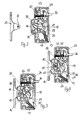
- locking device consists initially of a not shown on a door of a particular cabinet to be mounted closure holder 10 which carries a locking pin 11.
- a lock 12 can be fastened, which consists of two housing halves 13.
- a closing latch 14 is rotatably mounted about a housing-fixed bearing pin 15 which has a receiving opening 16 for the locking pin 11.
- the closing latch 14 is arranged in the housing 13 such that in the still too explanatory opening position of the latch of the locking pin 11 of the shutter holder 10 is inserted into the receiving opening 16 of the latch 14, while in the locked position, the latch 14 holds the locking pin 11 in its receiving opening 16.
- the closing latch 14 is acted upon by a tilt spring 17, which biases the latch 14 both in its open position as well as in its locking position and in this case passes through a dead center. In the two end positions, the tilt spring 17 is held by housing stops 18 in a defined position. Due to the bias of the tilt spring 17 results in a locking action for the latch 14 in the two end positions.
- a locking lever 19 is further rotatably mounted about a bearing pin 22 which has a blocking lug 20 at its end facing the latch 14, while at its opposite end relative to the bearing pin 22 an actuating lug 21 is present.
- a spring 23 which is supported on the housing and biases the safety lever 19 into its blocking position for the latch 14, in which the actuation lug 21 is in engagement with a blocking recess 28 provided on the outside of the latch 14.
- the actuating lug 21 is associated with an electromagnet 24, which attracts in the energized state, the actuating lug 21 to itself and thereby pivots the locking lever 19 against the action of the spring 23 in a release position for the latch.
- a microswitch 25 is still arranged in the housing 13 such that the microswitch 25 is actuated by an eccentric projection 30 located on the latch 14 in the open position of the latch.
- the microswitch 25 is connected via an electrical supply line 26 to a plug 27 arranged outside the housing, so that the signal emitted by the microswitch 25 during its switching can be tapped on the plug 27.
- the latch 14 In the functional position shown in Figure 2, the latch 14 is in its open position, in which the open side of its receiving opening 16 facing the closure holder 10 with locking pin 11. In this position, the latch 14 is held by the tilt spring 17. At the same time, the eccentric projection 30 actuates the microswitch 25 so that a signal can be tapped off the plug 27 so that the closing latch 14 is in the open position, so that the door with the closure holder attached thereto can be closed. This can be done for example by displaying a green lamp.
- the locking pin 11 engages in the receiving opening 16 of the latch 14. Since the corresponding boundary surface of the receiving opening 16 is formed so that the locking pin 11 pressing on this surface acts on the closing latch 14 in its closed position shown in Figure 2, the latch 14 rotates in the position shown in Figure 2, wherein this rotation by walking the tilt spring 17 is supported by the one end position in the end position shown in Figure 3, in which the tilt spring 17 holds the latch 14 in the closed position detent.
- the blocking lug 20 of the safety lever 19 slides along the outside of the latch 14 and engages under the pressure of the spring 23 in the blocking recess 28 of the latch 14, in which the blocking lug 20 abuts against the blocking recess 28 limiting paragraph 29 and a Reverse rotation of the latch 14 is prevented even with a corresponding train on the closure holder 10.
- the lock 12 is securely locked to the shutter holder 10; an opening is not possible.
Landscapes
- Engineering & Computer Science (AREA)
- Mechanical Engineering (AREA)
- Physics & Mathematics (AREA)
- Electromagnetism (AREA)
- Lock And Its Accessories (AREA)
- Casings For Electric Apparatus (AREA)
Applications Claiming Priority (1)
| Application Number | Priority Date | Filing Date | Title |
|---|---|---|---|
| DE200620015093 DE202006015093U1 (de) | 2006-09-30 | 2006-09-30 | Einpunkt-Verriegelungseinrichtung für insbesondere Schaltschränke |
Publications (2)
| Publication Number | Publication Date |
|---|---|
| EP1908902A2 true EP1908902A2 (fr) | 2008-04-09 |
| EP1908902A3 EP1908902A3 (fr) | 2011-07-06 |
Family
ID=37545561
Family Applications (1)
| Application Number | Title | Priority Date | Filing Date |
|---|---|---|---|
| EP20070017522 Withdrawn EP1908902A3 (fr) | 2006-09-30 | 2007-09-07 | Dispositif de verrouillage à un point en particulier pour des armoires électriques |
Country Status (3)
| Country | Link |
|---|---|
| US (1) | US20080087054A1 (fr) |
| EP (1) | EP1908902A3 (fr) |
| DE (1) | DE202006015093U1 (fr) |
Families Citing this family (3)
| Publication number | Priority date | Publication date | Assignee | Title |
|---|---|---|---|---|
| US9915082B2 (en) | 2014-11-07 | 2018-03-13 | Southco, Inc. | Cam latch |
| WO2021195516A1 (fr) * | 2020-03-27 | 2021-09-30 | Home Valet, Inc. | Appareil pour permettre le stockage ou le maintien d'articles, en particulier pour des livraisons et/ou des ramassages |
| US20240209656A1 (en) * | 2021-04-08 | 2024-06-27 | Southco, Inc. | Latch system with actuator, position sensor, or actuator and position sensor |
Family Cites Families (9)
| Publication number | Priority date | Publication date | Assignee | Title |
|---|---|---|---|---|
| US1899234A (en) * | 1932-03-16 | 1933-02-28 | Werth Charles Harold De | Closure fastener operator |
| DE3301636A1 (de) * | 1983-01-19 | 1984-07-19 | Bosch-Siemens Hausgeräte GmbH, 7000 Stuttgart | Verschlussvorrichtung fuer die tuer von elektrischen haushaltgeraeten |
| US6279361B1 (en) * | 1995-12-20 | 2001-08-28 | Vdo Adolf Schindling Ag | Lock in particular for motor vehicle doors |
| DE19600524B4 (de) * | 1995-12-20 | 2006-07-06 | Siemens Ag | Schloß, insbesondere für Kraftfahrzeugtüren |
| DE29806963U1 (de) * | 1998-04-17 | 1998-07-02 | Emka Beschlagteile Gmbh & Co Kg, 42551 Velbert | Vorreiberverschluß |
| DE19943483B4 (de) * | 1999-09-10 | 2008-03-06 | Kiekert Ag | Kraftfahrzeugtürverschluss |
| ITTO20020182A1 (it) * | 2002-03-05 | 2003-09-05 | Itw Ind Components Srl | Dispositivo di chiusura per il portello di un elettrodomestico, in particolare di una lavastoviglie. |
| DE10350710B4 (de) * | 2003-10-30 | 2021-01-07 | Marquardt Gmbh | Verschluß für ein Hausgerät |
| DE102004033735B4 (de) * | 2004-07-13 | 2006-07-27 | Huf Hülsbeck & Fürst Gmbh & Co. Kg | Vorrichtung zur Betätigung von Schlössern an Türen oder Klappen von Fahrzeugen |
-
2006
- 2006-09-30 DE DE200620015093 patent/DE202006015093U1/de not_active Expired - Lifetime
-
2007
- 2007-09-07 EP EP20070017522 patent/EP1908902A3/fr not_active Withdrawn
- 2007-09-28 US US11/904,770 patent/US20080087054A1/en not_active Abandoned
Also Published As
| Publication number | Publication date |
|---|---|
| EP1908902A3 (fr) | 2011-07-06 |
| US20080087054A1 (en) | 2008-04-17 |
| DE202006015093U1 (de) | 2006-11-30 |
Similar Documents
| Publication | Publication Date | Title |
|---|---|---|
| DE202012007145U1 (de) | Versenkbares Druckknopfelement für ein verschließbares oder abschließbares Möbelteil | |
| DE10194835B4 (de) | Hebelverschluss | |
| DE69207320T2 (de) | Verbesserter Schloss mit einer Einrichtung zwecks Öffnen im Notfall | |
| EP3016844B1 (fr) | Ensemble serrure pour porte-bagages | |
| DE3328284C2 (de) | Mit Permutationsschloß ausgerüsteter Verschluß für Koffer | |
| DE202018102221U1 (de) | Schaltmechanismus für Schloss, Schloss und Fahrzeug | |
| EP1908902A2 (fr) | Dispositif de verrouillage à un point en particulier pour des armoires électriques | |
| DE19643370A1 (de) | Einschnappklinke mit einem Knebel mit obenliegendem Drehpunkt und einem eingebauten Schalter | |
| WO2012049127A1 (fr) | Serrure | |
| EP2385195A2 (fr) | Serrure | |
| EP3091151B1 (fr) | Verrouillage de tringle pour une serrure de tringle | |
| WO2008019844A1 (fr) | Serrure à boulon verrouillable pour portes coulissantes | |
| EP1862614A1 (fr) | Fermeture à poignée bateau verrouillable | |
| DE102005017916A1 (de) | Gleitverschlussaufbau | |
| DE202015104480U1 (de) | Kompaktes selbstverriegelndes Einsteckschloss | |
| DE10246643B4 (de) | Elektromechanisches Schloss mit Sicherung gegen Fehlbetätigung | |
| DE202011106902U1 (de) | Einlageteil für Sicherheitsbeschlag | |
| DE2630019C3 (de) | Elektrisch betätigbares Schloß, insbesondere für Wertbehälter o.dgl | |
| EP0239855A1 (fr) | Serrure pour porte, fenêtre ou similaire | |
| WO2007104295A1 (fr) | Serrure pour une porte de maison ou d'appartement | |
| EP3216952B1 (fr) | Dispositif de verrouillage | |
| DE9207865U1 (de) | Durch einen Schlüssel- und/oder durch einen Drücker betätigbares Antipanik-Hotelschloß | |
| DE10048739C1 (de) | Olive zur Betätigung eines Schlosses, insbesondere eines Riegelschlosses | |
| DE366427C (de) | Scheibenfoermiges Haengeschloss | |
| CH608267A5 (en) | Blocking device for a door lock |
Legal Events
| Date | Code | Title | Description |
|---|---|---|---|
| PUAI | Public reference made under article 153(3) epc to a published international application that has entered the european phase |
Free format text: ORIGINAL CODE: 0009012 |
|
| AK | Designated contracting states |
Kind code of ref document: A2 Designated state(s): AT BE BG CH CY CZ DE DK EE ES FI FR GB GR HU IE IS IT LI LT LU LV MC MT NL PL PT RO SE SI SK TR |
|
| AX | Request for extension of the european patent |
Extension state: AL BA HR MK RS |
|
| PUAL | Search report despatched |
Free format text: ORIGINAL CODE: 0009013 |
|
| AK | Designated contracting states |
Kind code of ref document: A3 Designated state(s): AT BE BG CH CY CZ DE DK EE ES FI FR GB GR HU IE IS IT LI LT LU LV MC MT NL PL PT RO SE SI SK TR |
|
| AX | Request for extension of the european patent |
Extension state: AL BA HR MK RS |
|
| 17P | Request for examination filed |
Effective date: 20111111 |
|
| GRAP | Despatch of communication of intention to grant a patent |
Free format text: ORIGINAL CODE: EPIDOSNIGR1 |
|
| STAA | Information on the status of an ep patent application or granted ep patent |
Free format text: STATUS: THE APPLICATION HAS BEEN WITHDRAWN |
|
| AKX | Designation fees paid |
Designated state(s): DE |
|
| 18W | Application withdrawn |
Effective date: 20120303 |