EP1908894A1 - Gehäuseanordnung für eine markise - Google Patents
Gehäuseanordnung für eine markise Download PDFInfo
- Publication number
- EP1908894A1 EP1908894A1 EP06755363A EP06755363A EP1908894A1 EP 1908894 A1 EP1908894 A1 EP 1908894A1 EP 06755363 A EP06755363 A EP 06755363A EP 06755363 A EP06755363 A EP 06755363A EP 1908894 A1 EP1908894 A1 EP 1908894A1
- Authority
- EP
- European Patent Office
- Prior art keywords
- housing
- load bar
- canvas
- awning
- coupling
- Prior art date
- Legal status (The legal status is an assumption and is not a legal conclusion. Google has not performed a legal analysis and makes no representation as to the accuracy of the status listed.)
- Withdrawn
Links
Images

Classifications
-
- E—FIXED CONSTRUCTIONS
- E04—BUILDING
- E04F—FINISHING WORK ON BUILDINGS, e.g. STAIRS, FLOORS
- E04F10/00—Sunshades, e.g. Florentine blinds or jalousies; Outside screens; Awnings or baldachins
- E04F10/02—Sunshades, e.g. Florentine blinds or jalousies; Outside screens; Awnings or baldachins of flexible canopy materials, e.g. canvas ; Baldachins
- E04F10/06—Sunshades, e.g. Florentine blinds or jalousies; Outside screens; Awnings or baldachins of flexible canopy materials, e.g. canvas ; Baldachins comprising a roller-blind with means for holding the end away from a building
- E04F10/0685—Covers or housings for the rolled-up blind
- E04F10/0688—Covers or housings for the rolled-up blind with the housing taking up the articulated arms
-
- E—FIXED CONSTRUCTIONS
- E04—BUILDING
- E04F—FINISHING WORK ON BUILDINGS, e.g. STAIRS, FLOORS
- E04F10/00—Sunshades, e.g. Florentine blinds or jalousies; Outside screens; Awnings or baldachins
- E04F10/02—Sunshades, e.g. Florentine blinds or jalousies; Outside screens; Awnings or baldachins of flexible canopy materials, e.g. canvas ; Baldachins
- E04F10/06—Sunshades, e.g. Florentine blinds or jalousies; Outside screens; Awnings or baldachins of flexible canopy materials, e.g. canvas ; Baldachins comprising a roller-blind with means for holding the end away from a building
- E04F10/0611—Sunshades, e.g. Florentine blinds or jalousies; Outside screens; Awnings or baldachins of flexible canopy materials, e.g. canvas ; Baldachins comprising a roller-blind with means for holding the end away from a building with articulated arms supporting the movable end of the blind for deployment of the blind
-
- E—FIXED CONSTRUCTIONS
- E04—BUILDING
- E04F—FINISHING WORK ON BUILDINGS, e.g. STAIRS, FLOORS
- E04F10/00—Sunshades, e.g. Florentine blinds or jalousies; Outside screens; Awnings or baldachins
- E04F10/02—Sunshades, e.g. Florentine blinds or jalousies; Outside screens; Awnings or baldachins of flexible canopy materials, e.g. canvas ; Baldachins
- E04F10/06—Sunshades, e.g. Florentine blinds or jalousies; Outside screens; Awnings or baldachins of flexible canopy materials, e.g. canvas ; Baldachins comprising a roller-blind with means for holding the end away from a building
- E04F10/0692—Front bars
-
- E—FIXED CONSTRUCTIONS
- E04—BUILDING
- E04F—FINISHING WORK ON BUILDINGS, e.g. STAIRS, FLOORS
- E04F10/00—Sunshades, e.g. Florentine blinds or jalousies; Outside screens; Awnings or baldachins
- E04F10/02—Sunshades, e.g. Florentine blinds or jalousies; Outside screens; Awnings or baldachins of flexible canopy materials, e.g. canvas ; Baldachins
- E04F10/06—Sunshades, e.g. Florentine blinds or jalousies; Outside screens; Awnings or baldachins of flexible canopy materials, e.g. canvas ; Baldachins comprising a roller-blind with means for holding the end away from a building
- E04F10/0611—Sunshades, e.g. Florentine blinds or jalousies; Outside screens; Awnings or baldachins of flexible canopy materials, e.g. canvas ; Baldachins comprising a roller-blind with means for holding the end away from a building with articulated arms supporting the movable end of the blind for deployment of the blind
- E04F10/0618—Sunshades, e.g. Florentine blinds or jalousies; Outside screens; Awnings or baldachins of flexible canopy materials, e.g. canvas ; Baldachins comprising a roller-blind with means for holding the end away from a building with articulated arms supporting the movable end of the blind for deployment of the blind whereby the pivot axis of the articulation is perpendicular to the roller
-
- E—FIXED CONSTRUCTIONS
- E04—BUILDING
- E04F—FINISHING WORK ON BUILDINGS, e.g. STAIRS, FLOORS
- E04F10/00—Sunshades, e.g. Florentine blinds or jalousies; Outside screens; Awnings or baldachins
- E04F10/02—Sunshades, e.g. Florentine blinds or jalousies; Outside screens; Awnings or baldachins of flexible canopy materials, e.g. canvas ; Baldachins
- E04F10/06—Sunshades, e.g. Florentine blinds or jalousies; Outside screens; Awnings or baldachins of flexible canopy materials, e.g. canvas ; Baldachins comprising a roller-blind with means for holding the end away from a building
- E04F10/0662—Sunshades, e.g. Florentine blinds or jalousies; Outside screens; Awnings or baldachins of flexible canopy materials, e.g. canvas ; Baldachins comprising a roller-blind with means for holding the end away from a building with arrangements for fastening the blind to the building
Definitions
- the present invention generally relates to an awning case assembly provided with a housing wherein a winding bar for winding the canvas is housed, a load bar to which a front edge of the canvas is fixed, and a pair of foldable arms connected at one end to the housing and at the other end to the load bar.
- the load bar closes the housing with the wound canvas and the folded arms therein.
- a type of awning comprising a canvas, a winding tube on which said canvas is wound, a load bar joined to a front end of the canvas, and extensible articulated arms connected to the load bar and elastically pushed to extend the canvas as it is unwound and to keep the canvas taut.
- a manual or motor-driven mechanism allows rotate the winding tube so as to extend or draw in the canvas of the awning.
- the housing is closed at both side ends by end plates, each of which is rotatably coupled to a respective support part fixed in relation to a wall or another structure.
- Adjustment means allow adjusting and fixing the angular position of the end plates, and therefore of the case, with respect to the support parts.
- Positioning parts fixed inside the load bar collaborate in the correct positioning of the foldable arms inside the case in the closed case situation.
- European patent EP 0593389 discloses a support device with adjustable inclination for an awning case having the features described above.
- an awning case assembly of the type comprising a housing adapted to house a winding tube with a canvas wound thereon, said housing having a longitudinal opening allowing the passage of said canvas, and a load bar which is fixed to a front edge of said canvas and hingedly connected to distal ends of foldable arms having proximal ends hingedly connected to the housing.
- the mentioned load bar is adapted to be coupled to the housing in a folded awning situation, thus closing said longitudinal opening and covering said foldable arms.
- the awning case assembly of the present invention is characterized in that the load bar comprises a longitudinal fixing configuration adapted to fix said front edge of the canvas, a first longitudinal coupling configuration, adjacent to said fixing configuration and adapted to be coupled to a first longitudinal coupling edge of the housing, and a second longitudinal coupling configuration arranged at a distance from said first coupling configuration and adapted to be coupled to a second longitudinal coupling edge of the housing.
- the mentioned first and second coupling configurations and first and second coupling edges are arranged such that, during a closing operation of the case by winding the canvas, the second coupling configuration of the load bar is first coupled to the second coupling edge of the housing, such as to form a fulcrum line about which the load bar can rotate under the action of a pulling force exerted by the canvas on the fixing configuration until the first coupling configuration is coupled to the first coupling edge of the housing.
- the case 40 comprises a housing 41, individually shown in cross-section in Fig. 3 , two end plates 2 to which said housing 41 is fixed at its ends, only one of said end plates 2 being visible in Fig. 1 , and a load bar 42 individually shown in cross-section in Fig. 2 .
- Each of the mentioned end plates 2 is rotatably coupled to a support part 1 fixed in relation to a wall or another structure, for example, by means of an anchoring part 32 ( Figs. 7A-7C ) fixed to said wall or another structure, to which the support part is fixed by an engaging configuration 30 and a screw 43.
- the housing 41 is adapted to house a winding tube 25 with the canvas 26 wound thereon (see also Figs. 7A-7C ) and has a longitudinal opening 50 allowing the passage of said canvas 26.
- the load bar 42 is fixed to a front edge of said canvas 26.
- the assembly includes a pair of foldable arms 24, each of which has a proximal end hingedly connected to the corresponding end plate 2, on a side opposite to the support part 1, and a distal end hingedly connected to the load bar 42.
- the load bar 42 is thus supported and guided by the foldable arms 24.
- the foldable arms 24 are subjected to the force of elastic means (not shown) pushing the load bar 42 in a direction away from the housing 41. This force exerted by the elastic means is suitable to keep the canvas under tension whichever the position of the load bar 42.
- the housing 41 comprises an outer wall 55 surrounding the winding tube 25 and the canvas 26 at the upper, lower and rear sides, and a partition wall 56 surrounding the winding tube 25 and the canvas 26 at the front side except in the area of the mentioned longitudinal opening 50.
- the outer wall 55 of the housing 41 is advantageously formed by two extruded profiles 41a, 41b of a lightweight metal material, such as an aluminium alloy.
- the extruded profiles 41a, 41b are longitudinally connected to one another along a connecting line 71.
- the outer wall 55 of the housing 41 could be formed from a single profile with an equivalent result.
- One part of the outer wall 55 is a double wall forming one or more chambers 57 therein which, apart from offering additional protection for the case, form important reinforcing and stiffening elements against bending and torsion.
- Inner surfaces of said outer wall 55 and of said partition wall 56 define a substantially cylindrical surface facing the canvas 26 wound on the winding tube 25 and they preferably include a coating of plastic material with a low friction coefficient. In a folded awning situation ( Fig. 7C ) the partition wall 56 is thus placed between the canvas 26 wound on the winding tube 25 and the foldable arms 24.
- the outer wall 55 of the housing 41 has an upper front edge 62a and a lower front edge 62b.
- the partition wall 56 extends upwardly from said lower front edge 62b of the outer wall 55 and has a free upper edge in which a first coupling edge 52 of the housing 41 is longitudinally formed. This first coupling edge 52 of the housing 41 is located close to said upper front edge 62a of the outer wall 55 and separated therefrom by the longitudinal opening 50.
- a second coupling edge 54 of the housing 41 is longitudinally formed in the lower front edge 62b of said outer wall 55.
- the load bar 42 is adapted to be coupled to the housing 41 in said folded awning situation, closing the longitudinal opening 50 and covering the foldable arms 24.
- the load bar 42 comprises an externally convex closing wall 58 defining an inner hollow facing the winding tube 25, i.e., the partition wall 56, and which can at least partly house the foldable arms 24 in the folded awning situation.
- the mentioned closing wall 58 has an upper rear edge 70a and a lower rear edge 70b.
- a fixing configuration 64 adapted to fix said front edge of the canvas 26 by conventional means is longitudinally defined near said upper rear edge 70a, and a first coupling configuration 51 adapted to be coupled to the first coupling edge 52 of the housing 41 is longitudinally formed next to said fixing configuration 64.
- a second coupling configuration 53 is longitudinally formed next to said lower rear edge 70b, said second coupling configuration 53 being arranged at a distance from said first coupling configuration 51 and adapted to be coupled to said second longitudinal coupling edge 54 of the housing 41.
- the case 40 has a reverse construction, such that the longitudinal opening for the passage of the canvas is located at the lower region of the housing and the arms are located above the canvas.
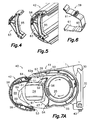
- Fig. 4 shows a reinforcing part 63 adapted to be internally fixed to the closing wall 58 of the load bar 42.
- Fig. 5 shows said reinforcing part 63 installed in a lower region of the closing wall 58 of the load bar 42.
- the reinforcing part defines a strut 65 which is arranged between an upper region and a lower region of the closing wall 58 reinforcing it against bending, torsion and a tendency to be squashed, which is especially useful in very long load bars 42.
- Fig. 6 shows a positioning part 59 adapted to be internally fixed to the closing wall 58 of the load bar 42.
- Two of these positioning parts 59 are preferably assembled in the load bar 42 and located in positions in which fitting configurations 60 of the positioning parts 59 cooperate with portions of the foldable arms 24 to keep the foldable arms 24 in a certain position inside the case 40 in the folded awning situation.
- the positioning parts 59 define slides 61 adapted to direct the foldable arms 24 in a sliding manner up to said fitting configurations 60 during a closing operation of the case.
- One of these positioning parts 59 is shown assembled in the load bar 41 in Figs. 7A-7C .
- the closing wall 58 of the load bar 42 is preferably formed from at least one extruded profile of a lightweight metal material, such as an aluminium alloy, whereas the reinforcing parts 63 and positioning parts 59 are preferably molded from a plastic material or a relatively ductile material that reduces the friction and makes the translational movement of the arms easier.
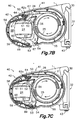
- FIG. 7A Several positions in a final stage of the closing operation of the case are shown in the sequence of views of Figs. 7A-7C .
- Fig. 7A a rotation of the winding tube 25 in the suitable direction winds the canvas 26 around the winding tube 25 and the canvas 26 pulls the load bar 41 towards the housing 42.
- the mentioned elastic means applied to the foldable arms 24 exert a suitable force to keep the canvas under tension whichever the position of the load bar 42, therefore, during the closing operation, the canvas 26 pulls the load bar against the force of said elastic means.
- the path of the closing movement of the load bar 42 has been determined by the folding movement of the foldable arms 24.
- Fig. 7B shows a later position in which the load bar 42 is closer to the housing 41.
- FIG. 7C shows the final stage of the closing operation.
- the first and second coupling configurations 51, 53 of the load bar 42 as well as the first and second coupling edges 52, 54 of the housing 41 are arranged such that during this final stage of the closing operation, the second coupling configuration 53 of the load bar 42 is first coupled to the second coupling edge 54 of the housing 41, forming a fulcrum line.
- End covers 68 provided with contours 69 facing the housing 41 are fixed at the ends of the load bar 42, and the end plates 2 comprise on their inner side, i.e. on the side opposite to the support part 1, in addition to a projection (not shown) with which the corresponding proximal end of the foldable arm is articulated, ramps 67 adapted to cooperate with said contours 69 of the end covers 68 of the load bar, such that in the final stage of the closing operation of the housing 40 shown in Fig.
- the cooperation of said ramps 67 with the contours 69 contributes to accurately driving the approaching movement of the load bar 42 until the initial coupling of the second coupling configuration 53 of the load bar 42 with the second coupling edge 54 of the housing 41 facilitating the subsequent coupling of the first coupling configuration 51 of the load bar 42 with the first coupling edge 52 of the housing 41.
- the upper front edge 62a of the outer wall 55 of the housing 41 forms a roof protecting the longitudinal opening 50, which is now virtually closed by the load bar 42, from the entrance of rainwater.
Landscapes
- Engineering & Computer Science (AREA)
- Architecture (AREA)
- Civil Engineering (AREA)
- Structural Engineering (AREA)
- Building Awnings And Sunshades (AREA)
- Tents Or Canopies (AREA)
Applications Claiming Priority (2)
| Application Number | Priority Date | Filing Date | Title |
|---|---|---|---|
| ES200501397A ES2246738B1 (es) | 2005-06-10 | 2005-06-10 | Conjunto de cofre para toldo. |
| PCT/ES2006/000279 WO2006131578A1 (es) | 2005-06-10 | 2006-05-24 | Conjunto de cofre para toldo |
Publications (2)
| Publication Number | Publication Date |
|---|---|
| EP1908894A1 true EP1908894A1 (de) | 2008-04-09 |
| EP1908894A4 EP1908894A4 (de) | 2014-12-31 |
Family
ID=35883647
Family Applications (1)
| Application Number | Title | Priority Date | Filing Date |
|---|---|---|---|
| EP06755363.6A Withdrawn EP1908894A4 (de) | 2005-06-10 | 2006-05-24 | Gehäuseanordnung für eine markise |
Country Status (4)
| Country | Link |
|---|---|
| US (1) | US8042595B2 (de) |
| EP (1) | EP1908894A4 (de) |
| ES (1) | ES2246738B1 (de) |
| WO (1) | WO2006131578A1 (de) |
Families Citing this family (8)
| Publication number | Priority date | Publication date | Assignee | Title |
|---|---|---|---|---|
| ES1063839Y (es) * | 2006-08-31 | 2007-10-01 | Llaza Sa | Conjunto de cofre para toldo enrollable. |
| DE102011119726B4 (de) * | 2011-11-30 | 2023-02-02 | Weinor Gmbh & Co. Kg | Kassettenmarkise mit verdeckten Befestigungskonsolen |
| WO2013128040A1 (es) * | 2012-02-27 | 2013-09-06 | Gaviota Simbac, S.L. | Pieza de refuerzo y carcasa de cofre de toldo |
| US9469997B2 (en) * | 2013-12-12 | 2016-10-18 | Carefree/Scott Fetzer Company | Lateral arm awning system and method of operation |
| US20170275884A1 (en) | 2016-03-25 | 2017-09-28 | Carefree/Scott Fetzer Company | Residential awning canopy assembly |
| US10947736B2 (en) | 2016-03-25 | 2021-03-16 | Carefree/Scott Fetzer Company | Residential awning canopy assembly |
| US11021878B2 (en) | 2017-07-07 | 2021-06-01 | Thule Nv | Connection system and awning structure with connection system |
| USD848640S1 (en) * | 2017-11-22 | 2019-05-14 | Dometic Sweden Ab | Awning arm end cover |
Family Cites Families (25)
| Publication number | Priority date | Publication date | Assignee | Title |
|---|---|---|---|---|
| US3187370A (en) * | 1961-11-22 | 1965-06-08 | Bruce J Bieda | Drapery hanger |
| DE2331365A1 (de) * | 1973-06-20 | 1975-01-02 | Clauss Markisen | Markise |
| US4258778A (en) * | 1978-02-15 | 1981-03-31 | Albert E. Upton | Roller bar construction |
| DE3206963C2 (de) * | 1982-02-26 | 1984-10-25 | Viktor 7032 Sindelfingen Lohausen | Kippgelenkarm-Markise |
| US4508126A (en) * | 1982-06-01 | 1985-04-02 | Valley Industries, Inc. | Retractable awning for mobile dwellings |
| US4469159A (en) * | 1983-09-19 | 1984-09-04 | Viktor Lohausen | Awning |
| US4917021A (en) * | 1989-02-21 | 1990-04-17 | Zeftek, Inc. | Door finger guide for doors on auto rack cars |
| DE9000939U1 (de) * | 1990-01-29 | 1990-04-12 | Warema Renkhoff Gmbh & Co Kg, 8772 Marktheidenfeld | Schutzabdeckung für eine Gelenkarm-Markise |
| DE4011876A1 (de) * | 1990-04-12 | 1991-10-17 | Viktor Lohausen | Gelenkarmmarkise |
| DE4106032A1 (de) * | 1990-05-09 | 1991-11-14 | Viktor Lohausen | Gelenkarmmarkise |
| EP0623183B1 (de) * | 1992-01-13 | 1998-03-25 | Cedis Licensing Gmbh | Profilmontageelement für die aufnahme und halterung verschiedener befestigungs- und/oder bewegungselemente einer markise |
| DE4209972C2 (de) * | 1992-03-27 | 1994-05-19 | Mhz Sonnenschutztech Gmbh | Markise |
| DE4219832C1 (de) * | 1992-06-17 | 1994-01-27 | Mhz Sonnenschutztech Gmbh | Kassettenmarkise |
| ATE147817T1 (de) * | 1992-10-16 | 1997-02-15 | Llaza Sa | Anordnung zur halterung von markisentuch, mit einstellbarer neigung |
| DE4402964B4 (de) * | 1994-02-01 | 2004-05-06 | "Weinor" Dieter Weiermann Gmbh & Co | Gelenkarmmarkise |
| DE19520162C5 (de) * | 1995-06-01 | 2006-08-31 | "Weinor" Dieter Weiermann Gmbh & Co | Markise |
| BE1009421A3 (nl) * | 1995-06-02 | 1997-03-04 | Brutsaert Accessories Nv | Oprolbare luifel. |
| DE59607426D1 (de) * | 1995-10-06 | 2001-09-06 | Cedis Licensing Gmbh Salzburg | Markise |
| DE29612905U1 (de) * | 1996-07-25 | 1996-10-02 | Schmitz Werke | Gelenkarmmarkise mit Regendach |
| DE19636877A1 (de) * | 1996-09-11 | 1998-03-12 | Brutsaert Accessoiries N V | Fahrzeug mit aufrollbarer Einbaumarkise und hierbei verwendete Einbaumarkise |
| NL1006038C1 (nl) * | 1997-05-13 | 1998-11-16 | Sunpoint B V | Zonnescherm met een snelmontage-systeem bestaande uit horizontale pennen aan het scherm die in een opname in een muursteun geplaatst worden en voorkeursuitvoeringen daarvan. |
| JP3576147B2 (ja) * | 2002-04-15 | 2004-10-13 | 博雄 向井 | 日除け装置取付具 |
| US6957679B2 (en) * | 2003-03-26 | 2005-10-25 | Powell & Powell Supply Co., Inc. | Retractable awning |
| JP4476936B2 (ja) * | 2003-08-01 | 2010-06-09 | ラサ エセア | 日除け用関節アーム |
| US7604036B2 (en) * | 2005-11-21 | 2009-10-20 | Carefree/Scott Fetzer Company | System for connecting awning canopy to support surface |
-
2005
- 2005-06-10 ES ES200501397A patent/ES2246738B1/es not_active Expired - Fee Related
-
2006
- 2006-05-24 WO PCT/ES2006/000279 patent/WO2006131578A1/es not_active Ceased
- 2006-05-24 EP EP06755363.6A patent/EP1908894A4/de not_active Withdrawn
- 2006-05-24 US US11/917,617 patent/US8042595B2/en not_active Expired - Fee Related
Non-Patent Citations (2)
| Title |
|---|
| No further relevant documents disclosed * |
| See also references of WO2006131578A1 * |
Also Published As
| Publication number | Publication date |
|---|---|
| US20090199974A1 (en) | 2009-08-13 |
| ES2246738B1 (es) | 2007-02-16 |
| ES2246738A1 (es) | 2006-02-16 |
| WO2006131578A1 (es) | 2006-12-14 |
| US8042595B2 (en) | 2011-10-25 |
| EP1908894A4 (de) | 2014-12-31 |
Similar Documents
| Publication | Publication Date | Title |
|---|---|---|
| US7114767B2 (en) | Window blind for a sliding roof system | |
| US7269871B2 (en) | Seal for aircraft boarding bridge including an extension mechanism | |
| EP2151339B1 (de) | Sonnenblendeanordnung und damit ausgestattete offene Dachkonstruktion | |
| US9840134B2 (en) | Sunshade assembly and open roof construction provided therewith | |
| CN111132863B (zh) | 用于车顶的卷帘系统 | |
| EP1908894A1 (de) | Gehäuseanordnung für eine markise | |
| HU223211B1 (hu) | Garázskapu | |
| CN101432159A (zh) | 用于运动遮盖元件的驱动装置,门组件以及该驱动装置的装配方法 | |
| ES2364270T3 (es) | Brazo articulado para toldo, con efecto elástico mejorado. | |
| CN102227327A (zh) | 遮阳组件和具有所述遮阳组件的开口顶棚结构 | |
| WO2015146754A1 (ja) | ドア開度調整装置 | |
| ITMI20040198U1 (it) | Anta con apertura a pressione | |
| US20100032992A1 (en) | Sunshade assembly and open roof construction provided therewith | |
| CN103732429B (zh) | 用于敞蓬车的可收回式顶篷 | |
| EP2674312B1 (de) | Öffnungsfähiges Dachsystem für ein Fahrzeug | |
| EP1908893B1 (de) | Markisengehäuseanordnung mit einer stütze und einer neigungsverstellanordnung | |
| EP0918118B1 (de) | Schirmstruktur | |
| US7409981B2 (en) | Shutter device with guideways | |
| JP3261553B2 (ja) | 伸縮門扉プッシュプルチェーンカバー装置 | |
| EP2942472B1 (de) | Verschlussvorrichtung vom typ jalousie, rollladen oder ähnliches, insbesondere für ein dachfenster | |
| JP4150657B2 (ja) | 横引き収納式網戸 | |
| US3505762A (en) | Lifting assembly for opening a hinged cover | |
| NL1018869C2 (nl) | Knikarm in het bijzonder toegepast in zonweringen. | |
| EP2397621A2 (de) | Sonnenschutz für Dachfensterrollo | |
| JP7725641B2 (ja) | シャッター装置の座板構造 |
Legal Events
| Date | Code | Title | Description |
|---|---|---|---|
| PUAI | Public reference made under article 153(3) epc to a published international application that has entered the european phase |
Free format text: ORIGINAL CODE: 0009012 |
|
| 17P | Request for examination filed |
Effective date: 20071224 |
|
| AK | Designated contracting states |
Kind code of ref document: A1 Designated state(s): AT BE BG CH CY CZ DE DK EE ES FI FR GB GR HU IE IS IT LI LT LU LV MC NL PL PT RO SE SI SK TR |
|
| DAX | Request for extension of the european patent (deleted) | ||
| A4 | Supplementary search report drawn up and despatched |
Effective date: 20141201 |
|
| RIC1 | Information provided on ipc code assigned before grant |
Ipc: E04F 10/06 20060101AFI20141125BHEP |
|
| STAA | Information on the status of an ep patent application or granted ep patent |
Free format text: STATUS: THE APPLICATION IS DEEMED TO BE WITHDRAWN |
|
| 18D | Application deemed to be withdrawn |
Effective date: 20150630 |
|
| 19U | Interruption of proceedings before grant |
Effective date: 20131105 |
|
| 19W | Proceedings resumed before grant after interruption of proceedings |
Effective date: 20160901 |
|
| RAP1 | Party data changed (applicant data changed or rights of an application transferred) |
Owner name: LLAZA WORLD, S.A. |