EP1908677B1 - Meter device and vehicle - Google Patents
Meter device and vehicle Download PDFInfo
- Publication number
- EP1908677B1 EP1908677B1 EP07253680A EP07253680A EP1908677B1 EP 1908677 B1 EP1908677 B1 EP 1908677B1 EP 07253680 A EP07253680 A EP 07253680A EP 07253680 A EP07253680 A EP 07253680A EP 1908677 B1 EP1908677 B1 EP 1908677B1
- Authority
- EP
- European Patent Office
- Prior art keywords
- frame
- meter device
- indication plate
- scale
- section
- Prior art date
- Legal status (The legal status is an assumption and is not a legal conclusion. Google has not performed a legal analysis and makes no representation as to the accuracy of the status listed.)
- Active
Links
Images


Classifications
-
- B—PERFORMING OPERATIONS; TRANSPORTING
- B60—VEHICLES IN GENERAL
- B60K—ARRANGEMENT OR MOUNTING OF PROPULSION UNITS OR OF TRANSMISSIONS IN VEHICLES; ARRANGEMENT OR MOUNTING OF PLURAL DIVERSE PRIME-MOVERS IN VEHICLES; AUXILIARY DRIVES FOR VEHICLES; INSTRUMENTATION OR DASHBOARDS FOR VEHICLES; ARRANGEMENTS IN CONNECTION WITH COOLING, AIR INTAKE, GAS EXHAUST OR FUEL SUPPLY OF PROPULSION UNITS IN VEHICLES
- B60K35/00—Instruments specially adapted for vehicles; Arrangement of instruments in or on vehicles
- B60K35/60—Instruments characterised by their location or relative disposition in or on vehicles
-
- B—PERFORMING OPERATIONS; TRANSPORTING
- B60—VEHICLES IN GENERAL
- B60K—ARRANGEMENT OR MOUNTING OF PROPULSION UNITS OR OF TRANSMISSIONS IN VEHICLES; ARRANGEMENT OR MOUNTING OF PLURAL DIVERSE PRIME-MOVERS IN VEHICLES; AUXILIARY DRIVES FOR VEHICLES; INSTRUMENTATION OR DASHBOARDS FOR VEHICLES; ARRANGEMENTS IN CONNECTION WITH COOLING, AIR INTAKE, GAS EXHAUST OR FUEL SUPPLY OF PROPULSION UNITS IN VEHICLES
- B60K2360/00—Indexing scheme associated with groups B60K35/00 or B60K37/00 relating to details of instruments or dashboards
- B60K2360/20—Optical features of instruments
- B60K2360/33—Illumination features
-
- B—PERFORMING OPERATIONS; TRANSPORTING
- B60—VEHICLES IN GENERAL
- B60Y—INDEXING SCHEME RELATING TO ASPECTS CROSS-CUTTING VEHICLE TECHNOLOGY
- B60Y2200/00—Type of vehicle
- B60Y2200/10—Road Vehicles
- B60Y2200/12—Motorcycles, Trikes; Quads; Scooters
-
- B—PERFORMING OPERATIONS; TRANSPORTING
- B62—LAND VEHICLES FOR TRAVELLING OTHERWISE THAN ON RAILS
- B62K—CYCLES; CYCLE FRAMES; CYCLE STEERING DEVICES; RIDER-OPERATED TERMINAL CONTROLS SPECIALLY ADAPTED FOR CYCLES; CYCLE AXLE SUSPENSIONS; CYCLE SIDE-CARS, FORECARS, OR THE LIKE
- B62K2202/00—Motorised scooters
-
- Y—GENERAL TAGGING OF NEW TECHNOLOGICAL DEVELOPMENTS; GENERAL TAGGING OF CROSS-SECTIONAL TECHNOLOGIES SPANNING OVER SEVERAL SECTIONS OF THE IPC; TECHNICAL SUBJECTS COVERED BY FORMER USPC CROSS-REFERENCE ART COLLECTIONS [XRACs] AND DIGESTS
- Y10—TECHNICAL SUBJECTS COVERED BY FORMER USPC
- Y10S—TECHNICAL SUBJECTS COVERED BY FORMER USPC CROSS-REFERENCE ART COLLECTIONS [XRACs] AND DIGESTS
- Y10S116/00—Signals and indicators
- Y10S116/05—Signals and indicators using light guides
Definitions
- the present invention relates to a meter device including an indication plate having an indication surface which indicates information concerning a measured amount, and a finger or pointer moving in an area above the indication plate, and also relates to a vehicle having a meter device.
- vehicles such as, for example, motorcycles have a meter device indicative of a measured amount, such as, for example, a speedometer indicative of a running speed.
- a manner for shining or illuminating a rim part of the meter panel is widely used for an analog indication type meter device, i.e., for a meter device that indicates a measured amount by a finger moving in an area above a meter panel which indicates information concerning the measured amount (for example, running speed) to enhance visibility of the meter device.
- a manner is known for enhancing the visibility of a meter device, particularly, easiness of discrimination from other meter devices or the like by providing a light guiding plate which guides light from a light source onto a rim part of the meter panel.
- a light guiding plate which guides light from a light source onto a rim part of the meter panel.
- the manner for enhancing the visibility of a conventional meter device has the following problem. That is, there is further room for improving the enhancement of the visibility, specifically, the enhancement of the easiness of the discrimination from other meter devices or the like.
- the scale comprises at least one scale ring that is not permeable to light and which is provided with openings.
- At least one light guide is provided. The light guide is located on a back surface of the scale ring. Ends of the light guide extend at least as far as the lower end of the through openings and may partially extend into and/or through the through openings. Light from the light source is injected into the light guide and the ends emit the light.
- EP0732679 describes a display panel of a speedometer that includes a light guide, a light source, a transparent sheet and a pointer.
- a masking is printed on the transparent sheet. Notches are defined by the masking so as to form shining parts.
- the light guide is formed in a disk shape, which corresponds to the disk shape of the transparent sheet.
- the light guide has a centre portion of uniform thickness and a tapered peripheral portion.
- a meter device comprising:
- the meter device may further comprise a finger adapted to move in an area above the indication surface of the indication plate.
- the meter device may further comprise a projecting scale section projecting from the indication plate frame toward the front side of the indication plate, wherein the projecting scale section is formed at a specific position corresponding to the measured amount.
- the projecting scale section may project inward from the rim part of the indication plate.
- a plurality of the projecting scale sections may be provided, and at least one projecting scale section may be formed at a position corresponding to a reference value of the measured amount.
- the at least one projecting scale section formed at a position corresponding to a reference value of the measured amount may be of a different size than the remaining projecting scale sections.
- the at least one projecting scale section may be larger than the remaining projecting scale sections.
- the indication plate frame may include:
- the frame outer end may be positioned more forward than the frame inner end on the front side of the indication plate.
- Each projecting scale section may include:
- the scale section outer end may be positioned more forward than the scale section inner end on the front side of the indication plate.
- the finger may be formed from a light guiding member to guide light from the light source or another light source.
- the meter device may further comprise:
- the meter device of the present invention may be juxtaposed with an other meter device, and the other meter device does not include an indication plate frame.
- a meter device including an indication plate having an indication surface which indicates information concerning a measured amount, and a finger moving in an area above the indication plate, has a light source, and an indication plate frame for surrounding at least a portion of a rim part of the indication plate, wherein the indication plate frame is formed from a light guiding member or material (for example, made of acrylic resin) which guides light from the light source, and the indication plate frame protrudes over the indication surface from a back side of the indication plate toward a front side thereof.
- a light guiding member or material for example, made of acrylic resin
- the indication plate frame surrounding at least the portion of the rim part of the indication plate and formed from the light guiding member protrudes over the indication surface from the back side of the indication plate toward the front side thereof.
- the meter device By shining the indication plate frame protruding over the indication surface from the back side of the indication plate toward the front side thereof, the meter device is more solidly visible.
- the indication plate frame may have a projecting scale section projecting toward the front side of the indication plate, and the projecting scale section may be formed at a specific position corresponding to the measured amount.
- the projecting scale section may project from the rim part to an inner side in the area above the indication plate.
- the indication plate frame may have a plurality of the projecting scale sections, and a size of the projecting scale section that is formed at a position corresponding to a reference value of the measured amount may be greater than respective sizes of the remainder projecting scale sections.
- the indication plate frame may have a frame inner end formed in the rim part side, a frame outer end formed out of the frame inner end, and a frame inclination section (formed between the frame inner end and the frame outer end.
- the frame outer end may be positioned more forward than the frame inner end on the front side of the indication plate.
- Each projecting scale section may have a scale section inner end formed in the rim part side, a scale section outer end formed out of the scale section inner end, and a scale section inclination part formed between the scale section inner end and the scale section outer end.
- the scale section outer end may be positioned more forward than the scale section inner end on the front side of the indication plate.
- the finger may be formed from a light guiding member to guide light from the light source or another light source.
- the meter device may further include an outer frame surrounding at least a portion of the indication plate frame outside.
- the outer frame may be treated (for example, plated) to reflect light.
- the meter device may be juxtaposed with another meter device, and only the meter device has the indication plate frame.
- a vehicle including a meter device according to the first or second aspects.
- a meter device that can further enhance the visibility, particularly, the easiness of the discrimination from other meter devices or the like, and also a vehicle having such a meter device can be provided.
- FIG. 1 is a left side elevational view of a motorcycle 10 according to an embodiment of the present invention.
- the motorcycle 10 is a so-called under-bone type motorcycle that has a body frame (not shown) positioned lower in comparison with a general straddle type motorcycle.
- the motorcycle 10 has a front wheel 20 and a rear wheel 70.
- the rear wheel 70 is driven by the power generated by an engine 50.
- the motorcycle 10 has a right and left pair of front forks 21 supporting the front wheel 20 for rotation.
- the front forks 21 allow the front wheel 20 to move (linear motion) in a vertical direction (actually, a direction defined with a certain caster angle) in accordance with variations of road conditions to absorb shocks which the front wheel 20 has received.
- the motorcycle 10 has a front cowling 30 for covering a portion of the front forks 21 and a steering shaft 22 (not shown in FIG. 1 , see FIG. 2 ).
- a handle bar unit 40 operated by a rider to change a direction of the front wheel 20 and a combination meter unit 100 are disposed above the front cowling 30.
- a structure of a meter device will now be described. Specifically, a structure of a combination meter unit 100 and a minute structure of a speedometer 120 (see FIG. 4 ) constructing the meter device in this embodiment will be described.
- FIG. 2 is a partial, enlarged, side elevational view of the combination meter unit 100 and the vicinity of the combination meter unit 100.
- FIG. 3 is a plan view of the combination meter unit 100 and the vicinity of the combination meter unit 100.
- the combination meter unit 100 is disposed in front of the handle bar unit 40.
- the combination meter unit 100 is fixed to the steering shaft 22 coupled with the front forks 21 (see FIG. 1 ).
- the handle bar unit 40 is configured with a left side handle bar 41L positioned on the left side, a right side handle bar 41R positioned on the right side and a handle crown 42 coupled with the steering shaft 22.
- the left side handle bar 41L and the right side handle bar 41R are coupled with the handle crown 42.
- the left side handle bar 41L is coupled with a left side handle bar coupling section 42a.
- the right side handle bar 41R is coupled with a right side handle bar coupling section 42b.
- the handle crown 42 curves along the combination meter unit 100. Specifically, the handle crown 42 curves along a bottom end portion 100a of the combination meter unit 100. Therefore, the bottom end portion 100a is positioned to enter an area of the handle crown 42 beyond a line L1 passing the left side handle bar coupling section 42a and the right side handle bar coupling section 42b.
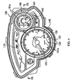
- FIG. 4 is a plan view of the combination meter unit 100. As shown in FIG. 4 , the combination meter unit 100 includes a speedometer 120, a fuel meter 160 and a shift indicator 170.
- the speedometer 120 is an analog indication type speedometer and includes a meter panel 121 (indication plate) and a finger or pointer 122.
- the finger 122 moves in an area above the meter panel 121 to indicate a running speed of the motorcycle 10.
- the finger 122 is formed from a light guiding member which guides light of a light source, specifically, the light of the finger lighting lamp 152 (not shown in FIG. 4 , see FIG. 7 ).
- the finger 122 is made from acrylic resin.
- the meter panel 121 has a light permeable part 121p (alphanumeric part such as, for example, "0,” “180” and “ km/h) which allows the light from the light source, specifically, from the meter lamp 151 (not shown in FIG. 4 , see FIG. 5 ) to pass therethrough.
- the permeable part 121p is printed with light-permeable ink.
- the permeable part 121p can be formed in such a manner that non-light-permeable ink is applied to the meter panel 121 and then the ink is removed in accordance with certain alphanumeric shapes to obtain the permeable part 121p.
- the meter panel 121 is positioned on a light guide 130.
- the light guide 130 is formed from a light guiding member to guide the light from the meter lamp 151 (see FIG. 5 ).
- the light guide 130 is made from acrylic resin.
- the light guide 130 is colored tangerine.
- a reflector ring 140 (outer frame) is provided and surrounds the light guide 130.
- the reflector ring 140 is treated, specifically plated, to reflect light.
- a fuel meter 160 (one of other meters, see FIG. 4 ) has a meter panel 161 and a finger 162 to indicate an amount of fuel present in a fuel tank (not shown) of the motorcycle 10.
- the meter panel 161 is similar to the meter panel 121 and has a permeable part 161p ("F," an icon for fuel or the like) which allows light to pass therethrough.
- the fuel meter 160 is positioned at a diagonally right upper location of the speedometer 120 and next to the speedometer 120.
- the diameter of the fuel meter 160 is smaller than the diameter of the speedometer 120.
- a shift indicator 170 is provided which indicates a selected transmission gear position (or neutral position).
- FIG. 5 is a cross sectional view of the combination meter unit 100, taken along the line F5-F5 shown in FIG. 4 .
- the speedometer 120 has the meter panel 121 and the finger 122.
- the light guide 130 is placed under the meter panel 121.
- the light guide 130 guides the light from the meter lamp 151.
- the guided light shines the vicinity of the rim part 121d ( FIG. 6 ) and the permeable part 121p of the meter panel 121.
- the fuel meter 160 is juxtaposed with the speedometer 120. That is, the finger 122 and the finger 162 are generally positioned at the same level in a depth direction (D1 direction in the figure). Also, a light guide 163 for guiding light to the permeable part 161p (see FIG. 4 ) from a lamp (not shown) is placed under the meter panel 161.
- the light guide 163 is positioned just under the meter panel 161. Dissimilarly to the light guide 130, the light guide 163 does not extend beyond the periphery of the meter panel 121.
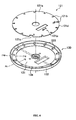
- FIG. 6 is an exploded perspective view of the meter panel 121 that forms the indication plate in this embodiment and of the light guide 130 that forms the indication plate frame in this embodiment.
- the meter panel 121 has an indication surface 121a indicating a running speed or the like.
- the permeable part 121p forms alphanumeric portions ("0,” “180” “ etc.) indicating the running speed or the like. Only some of the alphanumeric portions indicating the running speed or the like are shown in FIG. 6 .
- the meter panel 121 has notches 121b and a notch 121c engaging with scale projections 133 and a reference scale projection 134, respectively, which are formed on the light guide 130.
- the light guide 130 is disposed under the meter panel 121.
- the light guide 130 surrounds the rim part 121d of the meter panel 121.
- the light guide 130 has a generally disk-shaped bottom plate section 131 and a rim frame section 132 extending from the rim of the bottom plate section 131 toward the meter panel 121 so as to surround the meter panel 121.
- the light guide 130 has the scale projections 133 projecting inward from the rim part 121d of the meter panel 121 in an area above the meter panel 121 and the reference scale projection 134.
- the scale projections 133 and the reference scale projection 134 form projecting scale section(s).
- the scale projections 133 and the reference scale projection 134 project toward the front side of the meter panel 121.
- the scale projections 133 are formed at specific positions corresponding to running speeds (for example, 20km/h, 40km/h etc.).
- the reference scale projection 134 is formed at a position where the finger 122 points when a reference running speed is given, specifically, when the running speed of the motorcycle 10 is 0km/h.
- the light guide 130 has a plurality of the scale projections 133.
- a reference value of the measured amount specifically, a width of the reference scale projection 134 formed at the location corresponding to the reference running speed (0km/h) is longer than a width of each scale projection 133.
- FIG. 7 is a partially sectioned perspective view of the light guide 130.
- the light guide 130 is also used for guiding the light to the finger 122 from the light source.
- a light introducing section 135 and a light emitting section 136 are defined in the light guide 130.
- the light introducing section 135 introduces the light from the finger lighting lamp 152.
- the light of the finger lighting lamp 152 introduced by the light introducing section 135 is guided to the light emitting section 136.
- the light emitting section 136 emits the light from the finger lighting lamp 152.
- FIG. 8 is an explanatory view for explaining a situation in which the light from the finger lighting lamp 152 shines the finger 122. Additionally, the hatching expression of cross sections is omitted in FIG. 8 . As shown in FIG. 8 , an inclination part 136a which reflects the light (indicated by the dotted line) from the finger lighting lamp 152 upward, i.e., toward the finger 122 is formed at the light emitting section 136.
- an inclination part 122a which reflects the light from the finger lighting lamp 152 toward a tip end side of the finger 122 is formed in the finger 122.
- FIG. 9 is a cross sectional view of the light guide 130, taken along the line F9-F9, shown in FIG. 6 .
- the light guide 130 protrudes over the indication surface 121a from the back side (D1 direction side in the figure) of the meter panel 121 toward the front side (D2 direction side in the figure) thereof.
- the rim frame section 132 has an outer end 132a (frame outer end), an inner end 132b (frame inner end) and an inclination section 132c (frame inclination section).
- the inner end 132b is formed on the rim part 121d side of the meter panel 121.
- the outer end 132a is formed out of the inner end 132b.
- the outer end 132a is positioned more forward than the inner end 132b on the front side.
- the inclination section 132c is formed between the inner end 132b and the outer end 132a. That is, the rim frame section 132 has a mortar shape that descends from the outer end 132a toward the inner end 132b.
- FIG. 10 is a cross sectional view of the light guide 130 taken along the line F10-F10 shown in FIG. 6 .
- each scale projection 133 has an outer end 133a (scale section outer end), an inner end 133b (scale section inner end) and an inclination part 133c (scale section inclination part).
- the inner end 133b is formed on the rim part 121d side of the meter panel 121.
- the outer end 133a is formed outwardly of the inner end 133b.
- the outer end 132a is positioned more forward than the inner end 132b on the front side.
- the inclination part 133c is formed between the inner end 133b and the outer end 133a. That is, each scale projection 133 has a shape that descends from the outer end 133a toward the inner end 133b.
- the reference scale projection 134 has a lateral shape similar to that of the scale projection 133.
- the light guide 130 surrounding the rim part 121d of the meter panel 121 and made from acrylic resin protrudes over the indication surface 121a of the meter panel 121 from the back side of the meter panel 121 toward the front side thereof.
- the speedometer 120 is more solidly visible. That is, the visibility of the speedometer 120, particularly, the easiness of the discrimination from the fuel meter 160 and the shift indicator 170 can be further enhanced.
- the speedometer 120 is more solidly visible even though the meter lamp 151 does not shine the light guide.
- the light guide 130 has the scale projections 133 and the reference scale projection 134 which project inward of the meter panel 121 from the rim part 121d of the meter panel 121. Because the meter lamp 151 shines the scale projections 133 and the reference scale projection 134, the visibility of the speedometer 120, specifically, the situation in which the finger 122 points a specific running speed (20km/h, 40km/h etc.) can be easily seen by the rider.
- the width of the reference scale projection 134 formed at the location of "0km/h" is larger than the width of each scale projection 133. Therefore, the rider can easily recognize the reference position of the finger 122.
- the rim frame section 132 has the inclination section 132c that descends from the outer end 132a toward the inner end 132b. That is, the rim frame section 132 has a mortar shape. Therefore, the light is scattered toward the front side in the inclination section 132c. The speedometer 120 thus is more solidly visible.
- a gap G between the meter panel 121 and the rim frame section 132 can be inconspicuous, as shown in FIG. 9 .
- the rim frame section 132 has a mortar shape, the meter panel 121 having the notches 121b, 121c and the light guide 130 having the scale projections 133 and the reference scale projection 134 can be easily assembled with each other.
- Each scale projection 133 (including the reference scale projection 134) has the inclination part 133c that descends from the outer end 133a toward the inner end 133b. Therefore, the light is scattered toward the front side in the inclination part 133c. The speedometer 120 thus is more solidly visible.
- the finger 122 is also formed from the light guiding member, specifically, made from the acrylic resin. Also, because the plated reflector ring 140 ( FIG. 4 ) surrounds the light guide 130 externally in this embodiment, a wide area including the outside of the light guide 130 surrounding the meter panel 121 can be shined. That is, the visibility of the speedometer 120 can be further enhanced.
- the configuration of the light guide 130 can be changed to those shown in FIG. 11 (a) and (b) and FIG. 12 .
- a light guide 130A shown in FIG. 11(a) and a light guide 130B shown in FIG. 11(b) have different rim frame sections.
- the light guide 130A shown in FIG. 11(a) has scale sections 133A and a reference scale section 134A each extending outward and inward from a rim frame section 132.
- the light guide 130B shown in FIG. 11(b) has scale projections 133B and a reference scale projection 134B each extending outward from a rim frame section 132.
- the scale sections 133A, the scale projections 133B, the reference scale section 134A and the reference scale projection 134B project toward the front side of the meter panel 121.
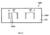
- FIG. 12 shows another variation of the light guide 130.
- a light guide 130C shown in FIG. 12 is not circularly shaped but has a rectangular shape.
- a finger 122C does not rotate as the finger 122 but moves parallel in a longitudinal direction of the meter panel 123.
- the light guide 130C has an outer frame section 132C. Also, the light guide 130C has a plurality of scale sections 137. The scale sections 137 do not contact with the outer frame section 132C and are formed at certain positions corresponding to indication amounts (for example, fuel). The scale sections 137 project toward the front side of the meter panel 121.
- the finger 122 and the light guide 130 are made from acrylic resin in the embodiment described above.
- the finger 122 or the light guide 130 can be made from materials other than the acrylic resin, for example, polycarbonate resin, ABS resin, polyethylene terephthalate (PET) or glass. That is, the materials used for making the finger 122 or the light guide 130 are only required to be light-permeable and have refraction rate higher than that of air.
- the finger 122 is also formed from the light guiding member in the embodiment described above, the finger is not necessarily formed from the light guiding member.
- the light guide 130 (rim frame section 132) and the reflector ring 140 are placed over the whole region of the rim part 121d of the meter panel 121.
- the light guide 130 (rim frame section 132) and the reflector ring 140 are not necessarily placed all over the whole region of the rim part 121d of the meter panel 121.
- the reflector ring 140 is not necessarily provided.
- the inclination section 132c whose outer end 132a is positioned more forward than the inner end 132b on the front side and the inclination section 133c whose outer end 133a is positioned more forward than the inner end 133b on the front side are formed.
- the inner end 132b or the inner end 133b can be positioned more forward on the front side.
- the inclination section 132c, the inclination section 133c, the scale projections 133 or the reference scale projection 134 are not necessarily formed.
- the width of the reference scale projection 134 is longer than the width of each scale projection 133.
- the length of the reference scale projection 134 can be longer or shorter than the length of the scale projection 133.
- the height of the reference scale projection 134 can be higher or lower than the height of the scale projection 133.
- the present invention can be applied to vehicles other than motorcycles, for example, vehicles such as automobiles or the like having a meter device.
Landscapes
- Engineering & Computer Science (AREA)
- Chemical & Material Sciences (AREA)
- Combustion & Propulsion (AREA)
- Transportation (AREA)
- Mechanical Engineering (AREA)
- Details Of Measuring Devices (AREA)
- Instrument Panels (AREA)
- Grinding Of Cylindrical And Plane Surfaces (AREA)
Abstract
Description
- The present invention relates to a meter device including an indication plate having an indication surface which indicates information concerning a measured amount, and a finger or pointer moving in an area above the indication plate, and also relates to a vehicle having a meter device.
- Conventionally, vehicles such as, for example, motorcycles have a meter device indicative of a measured amount, such as, for example, a speedometer indicative of a running speed. Also, a manner for shining or illuminating a rim part of the meter panel is widely used for an analog indication type meter device, i.e., for a meter device that indicates a measured amount by a finger moving in an area above a meter panel which indicates information concerning the measured amount (for example, running speed) to enhance visibility of the meter device.
- For example, a manner is known for enhancing the visibility of a meter device, particularly, easiness of discrimination from other meter devices or the like by providing a light guiding plate which guides light from a light source onto a rim part of the meter panel. Such an arrangement is disclosed in, for example,
JP-A-2004-340871 - However, the manner for enhancing the visibility of a conventional meter device, such as described above, has the following problem. That is, there is further room for improving the enhancement of the visibility, specifically, the enhancement of the easiness of the discrimination from other meter devices or the like.
- An example of a meter device is described by
W02006/027134 , which describes a measuring instrument having a graduated scale and a light source for illuminating the scale. The scale comprises at least one scale ring that is not permeable to light and which is provided with openings. At least one light guide is provided. The light guide is located on a back surface of the scale ring. Ends of the light guide extend at least as far as the lower end of the through openings and may partially extend into and/or through the through openings. Light from the light source is injected into the light guide and the ends emit the light. - Another example of a meter device is described by
EP0732679 , which describes a display panel of a speedometer that includes a light guide, a light source, a transparent sheet and a pointer. A masking is printed on the transparent sheet. Notches are defined by the masking so as to form shining parts. The light guide is formed in a disk shape, which corresponds to the disk shape of the transparent sheet. The light guide has a centre portion of uniform thickness and a tapered peripheral portion. - It is an object of the present invention to provide a meter device that can enhance the visibility thereof, particularly, the easiness of the discrimination from other meter devices or the like, and also to provide a vehicle having such a meter device.
- According to a first aspect of the present invention, there is provided a meter device comprising:
- an indication plate having an indication surface which indicates information concerning a measured amount;
- a light source; and
- an indication plate frame for surrounding at least a portion of a rim part of the indication plate,
- wherein the indication plate frame is at least partially formed from a light guiding member to guide light from the light source, and
- the indication plate frame protrudes over the indication surface from a back side of the indication plate toward a front side thereof.
- The meter device may further comprise a finger adapted to move in an area above the indication surface of the indication plate.
- The meter device may further comprise a projecting scale section projecting from the indication plate frame toward the front side of the indication plate, wherein the projecting scale section is formed at a specific position corresponding to the measured amount. The projecting scale section may project inward from the rim part of the indication plate.
- A plurality of the projecting scale sections may be provided, and at least one projecting scale section may be formed at a position corresponding to a reference value of the measured amount. The at least one projecting scale section formed at a position corresponding to a reference value of the measured amount may be of a different size than the remaining projecting scale sections. The at least one projecting scale section may be larger than the remaining projecting scale sections.
- The indication plate frame may include:
- a frame inner end formed on the rim part side;
- a frame outer end formed out of the frame inner end; and
- a frame inclination section formed between the frame inner end and the frame outer end.
- The frame outer end may be positioned more forward than the frame inner end on the front side of the indication plate.
- Each projecting scale section may include:
- a scale section inner end formed on the rim part side;
- a scale section outer end formed out of the scale section inner end; and
- a scale section inclination part formed between the scale section inner end and the scale section outer end.
- The scale section outer end may be positioned more forward than the scale section inner end on the front side of the indication plate.
- The finger may be formed from a light guiding member to guide light from the light source or another light source.
- The meter device may further comprise:
- an outer frame surrounding at least a portion of the indication plate frame outside, wherein the outer frame is treated to reflect light.
- The meter device of the present invention may be juxtaposed with an other meter device, and the other meter device does not include an indication plate frame.
- According to a second aspect of the present invention there is provided a meter device including an indication plate having an indication surface which indicates information concerning a measured amount, and a finger moving in an area above the indication plate, has a light source, and an indication plate frame for surrounding at least a portion of a rim part of the indication plate, wherein the indication plate frame is formed from a light guiding member or material (for example, made of acrylic resin) which guides light from the light source, and the indication plate frame protrudes over the indication surface from a back side of the indication plate toward a front side thereof.
- According to the meter device described above, the indication plate frame surrounding at least the portion of the rim part of the indication plate and formed from the light guiding member protrudes over the indication surface from the back side of the indication plate toward the front side thereof.
- By shining the indication plate frame protruding over the indication surface from the back side of the indication plate toward the front side thereof, the meter device is more solidly visible.
- The indication plate frame may have a projecting scale section projecting toward the front side of the indication plate, and the projecting scale section may be formed at a specific position corresponding to the measured amount.
- The projecting scale section may project from the rim part to an inner side in the area above the indication plate.
- The indication plate frame may have a plurality of the projecting scale sections, and a size of the projecting scale section that is formed at a position corresponding to a reference value of the measured amount may be greater than respective sizes of the remainder projecting scale sections.
- The indication plate frame may have a frame inner end formed in the rim part side, a frame outer end formed out of the frame inner end, and a frame inclination section (formed between the frame inner end and the frame outer end.
- The frame outer end may be positioned more forward than the frame inner end on the front side of the indication plate.
- Each projecting scale section may have a scale section inner end formed in the rim part side, a scale section outer end formed out of the scale section inner end, and a scale section inclination part formed between the scale section inner end and the scale section outer end.
- The scale section outer end may be positioned more forward than the scale section inner end on the front side of the indication plate.
- The finger may be formed from a light guiding member to guide light from the light source or another light source.
- The meter device may further include an outer frame surrounding at least a portion of the indication plate frame outside. The outer frame may be treated (for example, plated) to reflect light.
- The meter device may be juxtaposed with another meter device, and only the meter device has the indication plate frame.
- According to a third aspect of the present invention, there is provided a vehicle including a meter device according to the first or second aspects.
- According to the features of the present invention, a meter device that can further enhance the visibility, particularly, the easiness of the discrimination from other meter devices or the like, and also a vehicle having such a meter device can be provided.
- These and other aspects of the present invention will now be described, by way of example only, with reference to the accompanying drawings, in which:
-
FIG. 1 is a left side elevational view of a vehicle according to an embodiment of the present invention; -
FIG. 2 is a partial, enlarged, side elevational view of a combination meter unit according to an embodiment of the present invention and the vicinity of the combination meter unit; -
FIG. 3 is a plan view of the combination meter unit according to the embodiment of the present invention and the vicinity of the combination meter unit; -
FIG. 4 is a plan view of the combination meter unit according to the embodiment of the present invention; -
FIG. 5 is a cross sectional view of the combination meter unit, taken along the line F5-F5, shown inFIG. 4 ; -
FIG. 6 is an exploded perspective view of an indication plate and an indication plate frame according to the embodiment of the present invention; -
FIG. 7 is a partially sectioned perspective view of the indication plate frame according to the embodiment of the present invention; -
FIG. 8 is an explanatory view for explaining a situation in which the light from a light source according to the embodiment of the present invention shines a finger; -
FIG. 9 is a cross sectional view of the indication plate frame, taken along the line F9-F9, shown inFIG. 6 ; -
FIG. 10 is a cross sectional view of the light guide, taken along the line F10-F10, shown inFIG. 6 ; -
FIG. 11 is a plan view of an indication plate frame according to variations of the present invention; and -
FIG. 12 is a plan view of an indication plate frame according to a further variation of the present invention. - With reference to drawings, an embodiment of a vehicle according to the present invention will now be described. In the descriptions of the drawings, the same or similar portions are assigned with the same or similar reference numerals and symbols. However, it should be noted that the drawings are schematic and that for example ratios between respective dimensions are different from actual ones Accordingly, specific dimensions or the like should be decided in consideration of the following descriptions. Also, it is a matter of course that mutual dimensional relationships or ratios can be different from each other between the respective drawings.
-
FIG. 1 is a left side elevational view of amotorcycle 10 according to an embodiment of the present invention. As shown inFIG. 1 , themotorcycle 10 is a so-called under-bone type motorcycle that has a body frame (not shown) positioned lower in comparison with a general straddle type motorcycle. - The
motorcycle 10 has afront wheel 20 and arear wheel 70. Therear wheel 70 is driven by the power generated by anengine 50. - The
motorcycle 10 has a right and left pair offront forks 21 supporting thefront wheel 20 for rotation. Specifically, thefront forks 21 allow thefront wheel 20 to move (linear motion) in a vertical direction (actually, a direction defined with a certain caster angle) in accordance with variations of road conditions to absorb shocks which thefront wheel 20 has received. - The
motorcycle 10 has afront cowling 30 for covering a portion of thefront forks 21 and a steering shaft 22 (not shown inFIG. 1 , seeFIG. 2 ). Ahandle bar unit 40 operated by a rider to change a direction of thefront wheel 20 and acombination meter unit 100 are disposed above thefront cowling 30. - The structure of a meter device according to an embodiment of the present invention will now be described. Specifically, a structure of a
combination meter unit 100 and a minute structure of a speedometer 120 (seeFIG. 4 ) constructing the meter device in this embodiment will be described. -
FIG. 2 is a partial, enlarged, side elevational view of thecombination meter unit 100 and the vicinity of thecombination meter unit 100.FIG. 3 is a plan view of thecombination meter unit 100 and the vicinity of thecombination meter unit 100. - The
combination meter unit 100 is disposed in front of thehandle bar unit 40. Thecombination meter unit 100 is fixed to the steeringshaft 22 coupled with the front forks 21 (seeFIG. 1 ). - The
handle bar unit 40 is configured with a leftside handle bar 41L positioned on the left side, a rightside handle bar 41R positioned on the right side and ahandle crown 42 coupled with the steeringshaft 22. The leftside handle bar 41L and the rightside handle bar 41R are coupled with thehandle crown 42. Specifically, the leftside handle bar 41L is coupled with a left side handlebar coupling section 42a. Also, the rightside handle bar 41R is coupled with a right side handlebar coupling section 42b. - The
handle crown 42 curves along thecombination meter unit 100. Specifically, thehandle crown 42 curves along abottom end portion 100a of thecombination meter unit 100. Therefore, thebottom end portion 100a is positioned to enter an area of thehandle crown 42 beyond a line L1 passing the left side handlebar coupling section 42a and the right side handlebar coupling section 42b. -
FIG. 4 is a plan view of thecombination meter unit 100. As shown inFIG. 4 , thecombination meter unit 100 includes aspeedometer 120, afuel meter 160 and ashift indicator 170. - The
speedometer 120 is an analog indication type speedometer and includes a meter panel 121 (indication plate) and a finger orpointer 122. Thefinger 122 moves in an area above themeter panel 121 to indicate a running speed of themotorcycle 10. Thefinger 122 is formed from a light guiding member which guides light of a light source, specifically, the light of the finger lighting lamp 152 (not shown inFIG. 4 , seeFIG. 7 ). In this embodiment, thefinger 122 is made from acrylic resin. - The
meter panel 121 has a lightpermeable part 121p (alphanumeric part such as, for example, "0," "180" and " km/h) which allows the light from the light source, specifically, from the meter lamp 151 (not shown inFIG. 4 , seeFIG. 5 ) to pass therethrough. Thepermeable part 121p is printed with light-permeable ink. Alternatively, thepermeable part 121p can be formed in such a manner that non-light-permeable ink is applied to themeter panel 121 and then the ink is removed in accordance with certain alphanumeric shapes to obtain thepermeable part 121p. - The
meter panel 121 is positioned on alight guide 130. Thelight guide 130 is formed from a light guiding member to guide the light from the meter lamp 151 (seeFIG. 5 ). In this embodiment, thelight guide 130 is made from acrylic resin. Also, thelight guide 130 is colored tangerine. - Also, in this embodiment, a reflector ring 140 (outer frame) is provided and surrounds the
light guide 130. Thereflector ring 140 is treated, specifically plated, to reflect light. - A fuel meter 160 (one of other meters, see
FIG. 4 ) has ameter panel 161 and afinger 162 to indicate an amount of fuel present in a fuel tank (not shown) of themotorcycle 10. Themeter panel 161 is similar to themeter panel 121 and has apermeable part 161p ("F," an icon for fuel or the like) which allows light to pass therethrough. - The
fuel meter 160 is positioned at a diagonally right upper location of thespeedometer 120 and next to thespeedometer 120. The diameter of thefuel meter 160 is smaller than the diameter of thespeedometer 120. - A
shift indicator 170 is provided which indicates a selected transmission gear position (or neutral position). -
FIG. 5 is a cross sectional view of thecombination meter unit 100, taken along the line F5-F5 shown inFIG. 4 . As shown inFIG. 5 , thespeedometer 120 has themeter panel 121 and thefinger 122. Thelight guide 130 is placed under themeter panel 121. - The
light guide 130 guides the light from themeter lamp 151. The guided light shines the vicinity of therim part 121d (FIG. 6 ) and thepermeable part 121p of themeter panel 121. - In the cross section taken along the line F5-F5, the
fuel meter 160 is juxtaposed with thespeedometer 120. That is, thefinger 122 and thefinger 162 are generally positioned at the same level in a depth direction (D1 direction in the figure). Also, alight guide 163 for guiding light to thepermeable part 161p (seeFIG. 4 ) from a lamp (not shown) is placed under themeter panel 161. - The
light guide 163 is positioned just under themeter panel 161. Dissimilarly to thelight guide 130, thelight guide 163 does not extend beyond the periphery of themeter panel 121. - The detailed structure of the meter device according to this embodiment, i.e., the
speedometer 120 will now be described. -
FIG. 6 is an exploded perspective view of themeter panel 121 that forms the indication plate in this embodiment and of thelight guide 130 that forms the indication plate frame in this embodiment. - As shown in
FIG. 6 , themeter panel 121 has anindication surface 121a indicating a running speed or the like. Specifically, thepermeable part 121p forms alphanumeric portions ("0," "180" " etc.) indicating the running speed or the like. Only some of the alphanumeric portions indicating the running speed or the like are shown inFIG. 6 . - The
meter panel 121 hasnotches 121b and anotch 121c engaging withscale projections 133 and areference scale projection 134, respectively, which are formed on thelight guide 130. - The
light guide 130 is disposed under themeter panel 121. Thelight guide 130 surrounds therim part 121d of themeter panel 121. - The
light guide 130 has a generally disk-shapedbottom plate section 131 and arim frame section 132 extending from the rim of thebottom plate section 131 toward themeter panel 121 so as to surround themeter panel 121. - The
light guide 130 has thescale projections 133 projecting inward from therim part 121d of themeter panel 121 in an area above themeter panel 121 and thereference scale projection 134. In this embodiment, thescale projections 133 and thereference scale projection 134 form projecting scale section(s). Thescale projections 133 and thereference scale projection 134 project toward the front side of themeter panel 121. - The
scale projections 133 are formed at specific positions corresponding to running speeds (for example, 20km/h, 40km/h etc.). Thereference scale projection 134 is formed at a position where thefinger 122 points when a reference running speed is given, specifically, when the running speed of themotorcycle 10 is 0km/h. - That is, the
light guide 130 has a plurality of thescale projections 133. A reference value of the measured amount, specifically, a width of thereference scale projection 134 formed at the location corresponding to the reference running speed (0km/h) is longer than a width of eachscale projection 133. -
FIG. 7 is a partially sectioned perspective view of thelight guide 130. Thelight guide 130 is also used for guiding the light to thefinger 122 from the light source. As shown inFIG. 7 , alight introducing section 135 and alight emitting section 136 are defined in thelight guide 130. - The
light introducing section 135 introduces the light from thefinger lighting lamp 152. The light of thefinger lighting lamp 152 introduced by thelight introducing section 135 is guided to thelight emitting section 136. Thelight emitting section 136 emits the light from thefinger lighting lamp 152. -
FIG. 8 is an explanatory view for explaining a situation in which the light from thefinger lighting lamp 152 shines thefinger 122. Additionally, the hatching expression of cross sections is omitted inFIG. 8 . As shown inFIG. 8 , aninclination part 136a which reflects the light (indicated by the dotted line) from thefinger lighting lamp 152 upward, i.e., toward thefinger 122 is formed at thelight emitting section 136. - Also, an
inclination part 122a which reflects the light from thefinger lighting lamp 152 toward a tip end side of thefinger 122 is formed in thefinger 122. - The detailed configuration of the
rim frame section 132 of thelight guide 130 will now be described.FIG. 9 is a cross sectional view of thelight guide 130, taken along the line F9-F9, shown inFIG. 6 . - As shown in
FIG. 9 , thelight guide 130, specifically, therim frame section 132, protrudes over theindication surface 121a from the back side (D1 direction side in the figure) of themeter panel 121 toward the front side (D2 direction side in the figure) thereof. - The
rim frame section 132 has anouter end 132a (frame outer end), aninner end 132b (frame inner end) and aninclination section 132c (frame inclination section). - The
inner end 132b is formed on therim part 121d side of themeter panel 121. Theouter end 132a is formed out of theinner end 132b. Also, in this embodiment, theouter end 132a is positioned more forward than theinner end 132b on the front side. Theinclination section 132c is formed between theinner end 132b and theouter end 132a. That is, therim frame section 132 has a mortar shape that descends from theouter end 132a toward theinner end 132b. -
FIG. 10 is a cross sectional view of thelight guide 130 taken along the line F10-F10 shown inFIG. 6 . As shown inFIG. 10 , eachscale projection 133 has anouter end 133a (scale section outer end), aninner end 133b (scale section inner end) and aninclination part 133c (scale section inclination part). - The
inner end 133b is formed on therim part 121d side of themeter panel 121. Theouter end 133a is formed outwardly of theinner end 133b. Also, in this embodiment, theouter end 132a is positioned more forward than theinner end 132b on the front side. Theinclination part 133c is formed between theinner end 133b and theouter end 133a. That is, eachscale projection 133 has a shape that descends from theouter end 133a toward theinner end 133b. - Additionally, although not shown, the
reference scale projection 134 has a lateral shape similar to that of thescale projection 133. - According to the
combination meter unit 100, specifically thespeedometer 120, thelight guide 130 surrounding therim part 121d of themeter panel 121 and made from acrylic resin protrudes over theindication surface 121a of themeter panel 121 from the back side of themeter panel 121 toward the front side thereof. - Because the
meter lamp 151 shines thelight guide 130 that protrudes over theindication surface 121a from the back side of themeter panel 121 toward the front side thereof, thespeedometer 120 is more solidly visible. That is, the visibility of thespeedometer 120, particularly, the easiness of the discrimination from thefuel meter 160 and theshift indicator 170 can be further enhanced. - Also, because the
light guide 130 protrudes over theindication surface 121a of thelight guide 130, thespeedometer 120 is more solidly visible even though themeter lamp 151 does not shine the light guide. - In this embodiment, the
light guide 130 has thescale projections 133 and thereference scale projection 134 which project inward of themeter panel 121 from therim part 121d of themeter panel 121. Because themeter lamp 151 shines thescale projections 133 and thereference scale projection 134, the visibility of thespeedometer 120, specifically, the situation in which thefinger 122 points a specific running speed (20km/h, 40km/h etc.) can be easily seen by the rider. - Further, the width of the
reference scale projection 134 formed at the location of "0km/h" is larger than the width of eachscale projection 133. Therefore, the rider can easily recognize the reference position of thefinger 122. - In this embodiment, the
rim frame section 132 has theinclination section 132c that descends from theouter end 132a toward theinner end 132b. That is, therim frame section 132 has a mortar shape. Therefore, the light is scattered toward the front side in theinclination section 132c. Thespeedometer 120 thus is more solidly visible. - Also, because the
rim frame section 132 has a mortar shape, a gap G between themeter panel 121 and therim frame section 132 can be inconspicuous, as shown inFIG. 9 . Further, because therim frame section 132 has a mortar shape, themeter panel 121 having thenotches light guide 130 having thescale projections 133 and thereference scale projection 134 can be easily assembled with each other. - Each scale projection 133 (including the reference scale projection 134) has the
inclination part 133c that descends from theouter end 133a toward theinner end 133b. Therefore, the light is scattered toward the front side in theinclination part 133c. Thespeedometer 120 thus is more solidly visible. - In this embodiment, the
finger 122 is also formed from the light guiding member, specifically, made from the acrylic resin. Also, because the plated reflector ring 140 (FIG. 4 ) surrounds thelight guide 130 externally in this embodiment, a wide area including the outside of thelight guide 130 surrounding themeter panel 121 can be shined. That is, the visibility of thespeedometer 120 can be further enhanced. - Although the substance of the present invention is disclosed through the one embodiment described above, the descriptions and drawings forming a portion of this disclosure should not be recognized to limit the present invention. Persons skilled in the art can reveal various alternative embodiments from this disclosure.
- For example, the configuration of the
light guide 130 can be changed to those shown inFIG. 11 (a) and (b) andFIG. 12 . Alight guide 130A shown inFIG. 11(a) and alight guide 130B shown inFIG. 11(b) have different rim frame sections. - The
light guide 130A shown inFIG. 11(a) hasscale sections 133A and areference scale section 134A each extending outward and inward from arim frame section 132. Thelight guide 130B shown inFIG. 11(b) hasscale projections 133B and areference scale projection 134B each extending outward from arim frame section 132. Thescale sections 133A, thescale projections 133B, thereference scale section 134A and thereference scale projection 134B project toward the front side of themeter panel 121. -
FIG. 12 shows another variation of thelight guide 130. Alight guide 130C shown inFIG. 12 is not circularly shaped but has a rectangular shape. Afinger 122C does not rotate as thefinger 122 but moves parallel in a longitudinal direction of themeter panel 123. - The
light guide 130C has anouter frame section 132C. Also, thelight guide 130C has a plurality ofscale sections 137. Thescale sections 137 do not contact with theouter frame section 132C and are formed at certain positions corresponding to indication amounts (for example, fuel). Thescale sections 137 project toward the front side of themeter panel 121. - The
finger 122 and thelight guide 130 are made from acrylic resin in the embodiment described above. Thefinger 122 or thelight guide 130, however, can be made from materials other than the acrylic resin, for example, polycarbonate resin, ABS resin, polyethylene terephthalate (PET) or glass. That is, the materials used for making thefinger 122 or thelight guide 130 are only required to be light-permeable and have refraction rate higher than that of air. - Although the
finger 122 is also formed from the light guiding member in the embodiment described above, the finger is not necessarily formed from the light guiding member. - In the embodiment described above, the light guide 130 (rim frame section 132) and the
reflector ring 140 are placed over the whole region of therim part 121d of themeter panel 121. However, the light guide 130 (rim frame section 132) and thereflector ring 140 are not necessarily placed all over the whole region of therim part 121d of themeter panel 121. Also, thereflector ring 140 is not necessarily provided. - In the embodiment described above, the
inclination section 132c whoseouter end 132a is positioned more forward than theinner end 132b on the front side and theinclination section 133c whoseouter end 133a is positioned more forward than theinner end 133b on the front side are formed. However, theinner end 132b or theinner end 133b can be positioned more forward on the front side. Also, theinclination section 132c, theinclination section 133c, thescale projections 133 or thereference scale projection 134 are not necessarily formed. - Further, in the embodiment described above, the width of the
reference scale projection 134 is longer than the width of eachscale projection 133. However, the length of thereference scale projection 134 can be longer or shorter than the length of thescale projection 133. Otherwise, the height of thereference scale projection 134 can be higher or lower than the height of thescale projection 133. - Although the
motorcycle 10 is described as an example in the embodiment described above, the present invention can be applied to vehicles other than motorcycles, for example, vehicles such as automobiles or the like having a meter device. - As thus described, it is a matter of course that the present invention covers various embodiments or the like which are not described herein. Accordingly, the technical scope of the present invention can be decided by only the invention identifying items according to Claims which are appropriate in view of the above descriptions.
-
- 10:
- motorcycle
- 20:
- front wheel
- 21:
- front fork
- 22:
- steering shaft
- 30:
- front cowling
- 40:
- handle bar unit
- 41L:
- left side handle bar
- 41R:
- right side handle bar
- 42:
- handle crown
- 42a:
- left side handle coupling section
- 42b:
- right side handle coupling section
- 50:
- engine
- 70:
- rear wheel
- 100:
- combination meter unit
- 100a:
- bottom end portion
- 120:
- speedometer
- 121:
- meter panel
- 121a:
- indication surface
- 121b, 121c:
- notch
- 121d:
- rim part
- 121p:
- permeable part
- 122, 122C:
- finger
- 122a:
- inclination part
- 123:
- meter panel
- 130, 130A-130C:
- light guide
- 131:
- bottom plate section
- 132, 132C:
- rim frame section
- 132a:
- outer end
- 132b:
- inner end
- 132c:
- inclination section
- 133, 133B:
- scale projection
- 133A:
- scale section
- 133a:
- outer end
- 133b:
- inner end
- 133c:
- inclination section
- 134, 134B:
- reference scale projection
- 134A:
- reference scale section
- 135:
- light introducing section
- 136:
- light emitting section
- 136a:
- inclination part
- 137:
- scale section
- 140:
- reflector ring
- 151:
- meter lamp
- 152:
- finger lighting lamp
- 160:
- fuel meter
- 161:
- meter panel
- 161p:
- permeable part
- 162:
- finger
- 163:
- light guide
- 170:
- shift indicator
- G:
- gap
- L1:
- line
Claims (15)
- A meter device (120) comprising:an indication plate (121) having an indication surface (121a) which indicates information concerning a measured amount;a light source (151); andan indication plate frame (130) for surrounding at least a portion of a rim part (121d) of the indication plate (121),wherein the indication plate frame (130) is at least partially formed from a light guiding material to guide light from the light source (151), andthe indication plate frame (130) protrudes over the indication surface (121a) from a back side of the indication plate (121) toward a front side thereof.
- The meter device (120) according to Claim 1, further comprising a finger (122) adapted to move in an area above the indication surface (121a) of the indication plate (121).
- The meter device (120) according to Claim 1 or 2, further comprising a projecting scale section (133, 134) projecting from the indication plate frame (130) toward the front side of the indication plate (121), wherein the projecting scale section (133, 134) is formed at a specific position corresponding to the measured amount.
- The meter device (120) according to Claim 3, wherein the projecting scale section (133, 134) projects inward from the rim part (121d) of the indication plate (121).
- The meter device (120) according to Claim 3 or 4, wherein a plurality of the projecting scale sections (133, 134) are provided, and at least one projecting scale section (134) is formed at a position corresponding to a reference value of the measured amount.
- The meter device (120) according to Claim 5, wherein the at least one projecting scale section (134) formed at a position corresponding to a reference value of the measured amount is of a different size than the remaining projecting scale sections (133).
- The meter device (120) according to Claim 5 or 6, wherein the at least one projecting scale section (134) formed at a position corresponding to a reference value of the measured amount is larger than the remaining projecting scale sections (133).
- The meter device (120) according to any preceding Claim, wherein the indication plate frame (130) includes:a frame inner end (132b) formed on the rim part side;a frame outer end (132a) formed outwardly of the frame inner end (132b); anda frame inclination section (132c) formed between the frame inner end (132b) and the frame outer end (132a).
- The meter device (120) according to Claim 8, wherein the frame outer end (132a) is positioned more forward than the frame inner end (132b) on the front side of the indication plate (121).
- The meter device (120) according to any one of Claims 3 to 9, wherein each projecting scale section (133, 134) includes:a scale section inner end (133b) formed on the rim part side;a scale section outer end (133a) formed outwardly of the scale section inner end (133b); anda scale section inclination part (133c) formed between the scale section inner end (133b) and the scale section outer end (133a).
- The meter device (120) according to Claim 10, wherein the scale section outer end (133a) is positioned more forward than the scale section inner end (133b) on the front side of the indication plate (121).
- The meter device (120) according to any one of Claims 2 to 11, wherein the finger (122) is formed from a light guiding material to guide light from the light source (151) or another light source (152).
- The meter device (120) according to any preceding Claim, further comprising:an outer frame (140) surrounding at least an outer portion of the indication plate frame (130), wherein the outer frame (140) is treated to reflect light.
- The meter device (120) according to any preceding Claim, wherein the meter device (120) is juxtaposed with an other meter device, and the other meter device does not include an indication plate frame.
- A vehicle (10) comprising a meter device (120) according to any one of Claims 1 to 14.
Applications Claiming Priority (1)
| Application Number | Priority Date | Filing Date | Title |
|---|---|---|---|
| JP2006270001A JP2008089390A (en) | 2006-09-29 | 2006-09-29 | Meter device and vehicle |
Publications (3)
| Publication Number | Publication Date |
|---|---|
| EP1908677A2 EP1908677A2 (en) | 2008-04-09 |
| EP1908677A3 EP1908677A3 (en) | 2010-02-24 |
| EP1908677B1 true EP1908677B1 (en) | 2012-02-22 |
Family
ID=39032557
Family Applications (1)
| Application Number | Title | Priority Date | Filing Date |
|---|---|---|---|
| EP07253680A Active EP1908677B1 (en) | 2006-09-29 | 2007-09-17 | Meter device and vehicle |
Country Status (9)
| Country | Link |
|---|---|
| US (1) | US7798091B2 (en) |
| EP (1) | EP1908677B1 (en) |
| JP (1) | JP2008089390A (en) |
| AT (1) | ATE546345T1 (en) |
| BR (1) | BRPI0701657B1 (en) |
| CO (1) | CO5900035A1 (en) |
| ES (1) | ES2380959T3 (en) |
| MX (1) | MX2007012026A (en) |
| MY (1) | MY149018A (en) |
Families Citing this family (15)
| Publication number | Priority date | Publication date | Assignee | Title |
|---|---|---|---|---|
| JP5101986B2 (en) * | 2007-10-23 | 2012-12-19 | カルソニックカンセイ株式会社 | In-vehicle display device |
| KR101055088B1 (en) * | 2008-12-05 | 2011-08-08 | 기아자동차주식회사 | Cluster structure of vehicle |
| US8826846B2 (en) * | 2009-06-22 | 2014-09-09 | Nippon Seiki Co., Ltd. | Instrument device |
| JP5421881B2 (en) * | 2010-09-14 | 2014-02-19 | 本田技研工業株式会社 | Vehicle meter device |
| US8191272B1 (en) * | 2011-05-04 | 2012-06-05 | Chryl Light | Protractor apparatus |
| JP5823849B2 (en) * | 2011-12-20 | 2015-11-25 | 川崎重工業株式会社 | Vehicle meter display device and display method thereof |
| JP6110502B2 (en) * | 2013-09-17 | 2017-04-05 | 矢崎総業株式会社 | Scale structure and vehicle instrument |
| US20150158422A1 (en) * | 2013-12-06 | 2015-06-11 | Delphi Technologies, Inc. | Light-pipe cut from sheet stock for instrument panel |
| TWI507746B (en) * | 2014-02-07 | 2015-11-11 | E Ink Holdings Inc | Light guide module |
| US9500791B2 (en) * | 2014-09-22 | 2016-11-22 | Visteon Global Technolgoies, Inc. | Gradient light halo for a remote input device |
| JP2016070793A (en) * | 2014-09-30 | 2016-05-09 | 矢崎総業株式会社 | Instrument device |
| CN104608858A (en) * | 2014-12-04 | 2015-05-13 | 苏州欣航微电子有限公司 | Novel motorcycle liquid crystal instrument |
| DE202015008824U1 (en) * | 2015-12-29 | 2017-03-30 | Sur-Tech Surface-Technology GmbH | Display unit of a motor vehicle clock |
| TWM522874U (en) * | 2015-12-31 | 2016-06-01 | Cheng-Jie Wu | Vehicle dashboard panel replacement structure |
| US11002902B1 (en) * | 2019-11-08 | 2021-05-11 | Continental Automotive Systems, Inc. | Tick mark luminance adjustment tool |
Family Cites Families (18)
| Publication number | Priority date | Publication date | Assignee | Title |
|---|---|---|---|---|
| US2837053A (en) * | 1956-01-17 | 1958-06-03 | Bendix Aviat Corp | Indicating apparatus |
| US3699915A (en) * | 1971-05-19 | 1972-10-24 | Bendix Corp | Uniformly illuminated meter indicator |
| JPS551527A (en) * | 1978-06-21 | 1980-01-08 | Nissan Motor Co Ltd | Meter panel lighting structure of instrument panel |
| JP2996594B2 (en) * | 1994-08-04 | 2000-01-11 | 矢崎総業株式会社 | Distance integrator unit |
| JPH08254963A (en) | 1995-03-16 | 1996-10-01 | Hayashi Telempu Co Ltd | Display panel for in-vehicle equipment |
| JPH1048004A (en) * | 1996-08-02 | 1998-02-20 | Yazaki Corp | Lighting structure of instruments |
| DE19632381A1 (en) * | 1996-08-10 | 1998-02-12 | Mannesmann Vdo Ag | Combination instrument |
| JP3674425B2 (en) * | 1999-05-25 | 2005-07-20 | 株式会社デンソー | Vehicle instrument |
| JP4186362B2 (en) * | 1999-05-25 | 2008-11-26 | 株式会社デンソー | Instrument |
| US6585385B2 (en) * | 2000-06-29 | 2003-07-01 | Calsonic Kansei Corporation | Automotive meter with internal illumination structure |
| JP4273647B2 (en) * | 2000-09-01 | 2009-06-03 | 株式会社デンソー | Instrument |
| EP1271109B1 (en) * | 2001-06-19 | 2010-10-13 | Yazaki Corporation | Illuminable pointer instrument |
| JP2003252271A (en) * | 2002-02-27 | 2003-09-10 | Shimano Inc | Display device for bicycle |
| JP2004340871A (en) | 2003-05-19 | 2004-12-02 | Denso Corp | Vehicle instrument |
| DE102004043555A1 (en) | 2004-09-09 | 2006-03-30 | Daimlerchrysler Ag | Meter with an illuminable scale |
| US7093948B2 (en) * | 2004-12-15 | 2006-08-22 | Yazaki North America, Inc. | Display device with light guide |
| US7207117B1 (en) * | 2006-02-23 | 2007-04-24 | Denso International America, Inc. | Gauge with floodlighting, light ring, and hubless pointer |
| US7537363B2 (en) * | 2007-03-01 | 2009-05-26 | Denso International America, Inc. | Insert molding dial structure |
-
2006
- 2006-09-29 JP JP2006270001A patent/JP2008089390A/en active Pending
-
2007
- 2007-05-23 BR BRPI0701657-3A patent/BRPI0701657B1/en active IP Right Grant
- 2007-09-05 MY MYPI20071488A patent/MY149018A/en unknown
- 2007-09-17 EP EP07253680A patent/EP1908677B1/en active Active
- 2007-09-17 ES ES07253680T patent/ES2380959T3/en active Active
- 2007-09-17 AT AT07253680T patent/ATE546345T1/en active
- 2007-09-24 US US11/860,429 patent/US7798091B2/en active Active
- 2007-09-28 CO CO07101627A patent/CO5900035A1/en active IP Right Grant
- 2007-09-28 MX MX2007012026A patent/MX2007012026A/en active IP Right Grant
Also Published As
| Publication number | Publication date |
|---|---|
| ATE546345T1 (en) | 2012-03-15 |
| EP1908677A3 (en) | 2010-02-24 |
| JP2008089390A (en) | 2008-04-17 |
| US7798091B2 (en) | 2010-09-21 |
| US20080236474A1 (en) | 2008-10-02 |
| ES2380959T3 (en) | 2012-05-21 |
| MX2007012026A (en) | 2009-02-12 |
| CO5900035A1 (en) | 2008-03-31 |
| MY149018A (en) | 2013-06-28 |
| BRPI0701657B1 (en) | 2019-04-09 |
| EP1908677A2 (en) | 2008-04-09 |
| BRPI0701657A (en) | 2008-05-27 |
Similar Documents
| Publication | Publication Date | Title |
|---|---|---|
| EP1908677B1 (en) | Meter device and vehicle | |
| JP5067639B2 (en) | Instrument lighting device | |
| US20030189819A1 (en) | Pointer type indicator | |
| ITMI970253A1 (en) | DASHBOARD FOR MOTORCYCLE EASY TO POSITION ON THE VEHICLE | |
| US7374323B1 (en) | Self-illumination applique system and method | |
| CN102449440B (en) | Meter illumination device | |
| JP2015075328A (en) | Dial structure and automotive meter | |
| JP2011013154A (en) | Instrument device | |
| JP2016128777A (en) | Vehicle meter | |
| JP5505643B2 (en) | Instrument device | |
| JP2012154798A (en) | Pointer member, pointer unit, and pointer instrument | |
| JP5004222B2 (en) | Display device | |
| US20100002412A1 (en) | Vehicle meter | |
| JPWO2019003496A1 (en) | Vehicle instrument | |
| JP5822889B2 (en) | Vehicle meter device | |
| JP6407853B2 (en) | Vehicle instrument | |
| JP5815249B2 (en) | Pointer unit and pointer meter | |
| JP2002264691A (en) | Pointer display | |
| JP2008215883A (en) | Meter device and vehicle | |
| JP2012154796A (en) | Pointer member, pointer unit, and pointer instrument | |
| JP4075279B2 (en) | Indicators and instruments | |
| JP2002340629A (en) | Measuring instrument | |
| JP2008310186A (en) | Display device | |
| JP4947425B2 (en) | Liquid crystal display | |
| JP2003279387A (en) | Measuring instrument for vehicle |
Legal Events
| Date | Code | Title | Description |
|---|---|---|---|
| PUAI | Public reference made under article 153(3) epc to a published international application that has entered the european phase |
Free format text: ORIGINAL CODE: 0009012 |
|
| 17P | Request for examination filed |
Effective date: 20070926 |
|
| AK | Designated contracting states |
Kind code of ref document: A2 Designated state(s): AT BE BG CH CY CZ DE DK EE ES FI FR GB GR HU IE IS IT LI LT LU LV MC MT NL PL PT RO SE SI SK TR |
|
| AX | Request for extension of the european patent |
Extension state: AL BA HR MK RS |
|
| PUAL | Search report despatched |
Free format text: ORIGINAL CODE: 0009013 |
|
| AK | Designated contracting states |
Kind code of ref document: A3 Designated state(s): AT BE BG CH CY CZ DE DK EE ES FI FR GB GR HU IE IS IT LI LT LU LV MC MT NL PL PT RO SE SI SK TR |
|
| AX | Request for extension of the european patent |
Extension state: AL BA HR MK RS |
|
| AKX | Designation fees paid |
Designated state(s): AT BE BG CH CY CZ DE DK EE ES FI FR GB GR HU IE IS IT LI LT LU LV MC MT NL PL PT RO SE SI SK TR |
|
| GRAP | Despatch of communication of intention to grant a patent |
Free format text: ORIGINAL CODE: EPIDOSNIGR1 |
|
| RAP1 | Party data changed (applicant data changed or rights of an application transferred) |
Owner name: YAMAHA HATSUDOKI KABUSHIKI KAISHA |
|
| RIN1 | Information on inventor provided before grant (corrected) |
Inventor name: WORAKASEMSUK, PAIRUCH Inventor name: SUITA, YOSHIKAZU |
|
| REG | Reference to a national code |
Ref country code: DE Ref legal event code: R079 Ref document number: 602007020824 Country of ref document: DE Free format text: PREVIOUS MAIN CLASS: B62J0039000000 Ipc: B62J0099000000 |
|
| GRAS | Grant fee paid |
Free format text: ORIGINAL CODE: EPIDOSNIGR3 |
|
| GRAA | (expected) grant |
Free format text: ORIGINAL CODE: 0009210 |
|
| RIC1 | Information provided on ipc code assigned before grant |
Ipc: B60K 35/00 20060101ALI20111221BHEP Ipc: B62J 99/00 20090101AFI20111221BHEP |
|
| AK | Designated contracting states |
Kind code of ref document: B1 Designated state(s): AT BE BG CH CY CZ DE DK EE ES FI FR GB GR HU IE IS IT LI LT LU LV MC MT NL PL PT RO SE SI SK TR |
|
| REG | Reference to a national code |
Ref country code: GB Ref legal event code: FG4D |
|
| REG | Reference to a national code |
Ref country code: CH Ref legal event code: EP |
|
| REG | Reference to a national code |
Ref country code: AT Ref legal event code: REF Ref document number: 546345 Country of ref document: AT Kind code of ref document: T Effective date: 20120315 |
|
| REG | Reference to a national code |
Ref country code: IE Ref legal event code: FG4D |
|
| REG | Reference to a national code |
Ref country code: DE Ref legal event code: R096 Ref document number: 602007020824 Country of ref document: DE Effective date: 20120419 |
|
| REG | Reference to a national code |
Ref country code: ES Ref legal event code: FG2A Ref document number: 2380959 Country of ref document: ES Kind code of ref document: T3 Effective date: 20120521 |
|
| REG | Reference to a national code |
Ref country code: NL Ref legal event code: VDEP Effective date: 20120222 |
|
| LTIE | Lt: invalidation of european patent or patent extension |
Effective date: 20120222 |
|
| PG25 | Lapsed in a contracting state [announced via postgrant information from national office to epo] |
Ref country code: LT Free format text: LAPSE BECAUSE OF FAILURE TO SUBMIT A TRANSLATION OF THE DESCRIPTION OR TO PAY THE FEE WITHIN THE PRESCRIBED TIME-LIMIT Effective date: 20120222 Ref country code: NL Free format text: LAPSE BECAUSE OF FAILURE TO SUBMIT A TRANSLATION OF THE DESCRIPTION OR TO PAY THE FEE WITHIN THE PRESCRIBED TIME-LIMIT Effective date: 20120222 Ref country code: IS Free format text: LAPSE BECAUSE OF FAILURE TO SUBMIT A TRANSLATION OF THE DESCRIPTION OR TO PAY THE FEE WITHIN THE PRESCRIBED TIME-LIMIT Effective date: 20120622 |
|
| PG25 | Lapsed in a contracting state [announced via postgrant information from national office to epo] |
Ref country code: LV Free format text: LAPSE BECAUSE OF FAILURE TO SUBMIT A TRANSLATION OF THE DESCRIPTION OR TO PAY THE FEE WITHIN THE PRESCRIBED TIME-LIMIT Effective date: 20120222 Ref country code: FI Free format text: LAPSE BECAUSE OF FAILURE TO SUBMIT A TRANSLATION OF THE DESCRIPTION OR TO PAY THE FEE WITHIN THE PRESCRIBED TIME-LIMIT Effective date: 20120222 Ref country code: PT Free format text: LAPSE BECAUSE OF FAILURE TO SUBMIT A TRANSLATION OF THE DESCRIPTION OR TO PAY THE FEE WITHIN THE PRESCRIBED TIME-LIMIT Effective date: 20120622 Ref country code: BE Free format text: LAPSE BECAUSE OF FAILURE TO SUBMIT A TRANSLATION OF THE DESCRIPTION OR TO PAY THE FEE WITHIN THE PRESCRIBED TIME-LIMIT Effective date: 20120222 Ref country code: GR Free format text: LAPSE BECAUSE OF FAILURE TO SUBMIT A TRANSLATION OF THE DESCRIPTION OR TO PAY THE FEE WITHIN THE PRESCRIBED TIME-LIMIT Effective date: 20120523 |
|
| REG | Reference to a national code |
Ref country code: AT Ref legal event code: MK05 Ref document number: 546345 Country of ref document: AT Kind code of ref document: T Effective date: 20120222 |
|
| PG25 | Lapsed in a contracting state [announced via postgrant information from national office to epo] |
Ref country code: CY Free format text: LAPSE BECAUSE OF FAILURE TO SUBMIT A TRANSLATION OF THE DESCRIPTION OR TO PAY THE FEE WITHIN THE PRESCRIBED TIME-LIMIT Effective date: 20120222 |
|
| PG25 | Lapsed in a contracting state [announced via postgrant information from national office to epo] |
Ref country code: SI Free format text: LAPSE BECAUSE OF FAILURE TO SUBMIT A TRANSLATION OF THE DESCRIPTION OR TO PAY THE FEE WITHIN THE PRESCRIBED TIME-LIMIT Effective date: 20120222 Ref country code: SE Free format text: LAPSE BECAUSE OF FAILURE TO SUBMIT A TRANSLATION OF THE DESCRIPTION OR TO PAY THE FEE WITHIN THE PRESCRIBED TIME-LIMIT Effective date: 20120222 Ref country code: DK Free format text: LAPSE BECAUSE OF FAILURE TO SUBMIT A TRANSLATION OF THE DESCRIPTION OR TO PAY THE FEE WITHIN THE PRESCRIBED TIME-LIMIT Effective date: 20120222 Ref country code: PL Free format text: LAPSE BECAUSE OF FAILURE TO SUBMIT A TRANSLATION OF THE DESCRIPTION OR TO PAY THE FEE WITHIN THE PRESCRIBED TIME-LIMIT Effective date: 20120222 Ref country code: EE Free format text: LAPSE BECAUSE OF FAILURE TO SUBMIT A TRANSLATION OF THE DESCRIPTION OR TO PAY THE FEE WITHIN THE PRESCRIBED TIME-LIMIT Effective date: 20120222 Ref country code: CZ Free format text: LAPSE BECAUSE OF FAILURE TO SUBMIT A TRANSLATION OF THE DESCRIPTION OR TO PAY THE FEE WITHIN THE PRESCRIBED TIME-LIMIT Effective date: 20120222 Ref country code: RO Free format text: LAPSE BECAUSE OF FAILURE TO SUBMIT A TRANSLATION OF THE DESCRIPTION OR TO PAY THE FEE WITHIN THE PRESCRIBED TIME-LIMIT Effective date: 20120222 |
|
| PG25 | Lapsed in a contracting state [announced via postgrant information from national office to epo] |
Ref country code: SK Free format text: LAPSE BECAUSE OF FAILURE TO SUBMIT A TRANSLATION OF THE DESCRIPTION OR TO PAY THE FEE WITHIN THE PRESCRIBED TIME-LIMIT Effective date: 20120222 |
|
| PLBE | No opposition filed within time limit |
Free format text: ORIGINAL CODE: 0009261 |
|
| STAA | Information on the status of an ep patent application or granted ep patent |
Free format text: STATUS: NO OPPOSITION FILED WITHIN TIME LIMIT |
|
| 26N | No opposition filed |
Effective date: 20121123 |
|
| PG25 | Lapsed in a contracting state [announced via postgrant information from national office to epo] |
Ref country code: AT Free format text: LAPSE BECAUSE OF FAILURE TO SUBMIT A TRANSLATION OF THE DESCRIPTION OR TO PAY THE FEE WITHIN THE PRESCRIBED TIME-LIMIT Effective date: 20120222 |
|
| REG | Reference to a national code |
Ref country code: DE Ref legal event code: R097 Ref document number: 602007020824 Country of ref document: DE Effective date: 20121123 |
|
| PG25 | Lapsed in a contracting state [announced via postgrant information from national office to epo] |
Ref country code: MC Free format text: LAPSE BECAUSE OF NON-PAYMENT OF DUE FEES Effective date: 20120930 |
|
| REG | Reference to a national code |
Ref country code: CH Ref legal event code: PL |
|
| GBPC | Gb: european patent ceased through non-payment of renewal fee |
Effective date: 20120917 |
|
| REG | Reference to a national code |
Ref country code: IE Ref legal event code: MM4A |
|
| REG | Reference to a national code |
Ref country code: FR Ref legal event code: ST Effective date: 20130531 |
|
| PG25 | Lapsed in a contracting state [announced via postgrant information from national office to epo] |
Ref country code: CH Free format text: LAPSE BECAUSE OF NON-PAYMENT OF DUE FEES Effective date: 20120930 Ref country code: DE Free format text: LAPSE BECAUSE OF NON-PAYMENT OF DUE FEES Effective date: 20130403 Ref country code: IE Free format text: LAPSE BECAUSE OF NON-PAYMENT OF DUE FEES Effective date: 20120917 Ref country code: LI Free format text: LAPSE BECAUSE OF NON-PAYMENT OF DUE FEES Effective date: 20120930 Ref country code: BG Free format text: LAPSE BECAUSE OF FAILURE TO SUBMIT A TRANSLATION OF THE DESCRIPTION OR TO PAY THE FEE WITHIN THE PRESCRIBED TIME-LIMIT Effective date: 20120522 Ref country code: GB Free format text: LAPSE BECAUSE OF NON-PAYMENT OF DUE FEES Effective date: 20120917 |
|
| PG25 | Lapsed in a contracting state [announced via postgrant information from national office to epo] |
Ref country code: FR Free format text: LAPSE BECAUSE OF NON-PAYMENT OF DUE FEES Effective date: 20121001 |
|
| REG | Reference to a national code |
Ref country code: DE Ref legal event code: R119 Ref document number: 602007020824 Country of ref document: DE Effective date: 20130403 |
|
| PG25 | Lapsed in a contracting state [announced via postgrant information from national office to epo] |
Ref country code: MT Free format text: LAPSE BECAUSE OF FAILURE TO SUBMIT A TRANSLATION OF THE DESCRIPTION OR TO PAY THE FEE WITHIN THE PRESCRIBED TIME-LIMIT Effective date: 20120222 |
|
| PG25 | Lapsed in a contracting state [announced via postgrant information from national office to epo] |
Ref country code: TR Free format text: LAPSE BECAUSE OF FAILURE TO SUBMIT A TRANSLATION OF THE DESCRIPTION OR TO PAY THE FEE WITHIN THE PRESCRIBED TIME-LIMIT Effective date: 20120222 |
|
| PG25 | Lapsed in a contracting state [announced via postgrant information from national office to epo] |
Ref country code: LU Free format text: LAPSE BECAUSE OF NON-PAYMENT OF DUE FEES Effective date: 20120917 |
|
| PG25 | Lapsed in a contracting state [announced via postgrant information from national office to epo] |
Ref country code: HU Free format text: LAPSE BECAUSE OF FAILURE TO SUBMIT A TRANSLATION OF THE DESCRIPTION OR TO PAY THE FEE WITHIN THE PRESCRIBED TIME-LIMIT Effective date: 20070917 |
|
| P01 | Opt-out of the competence of the unified patent court (upc) registered |
Effective date: 20230526 |
|
| PGFP | Annual fee paid to national office [announced via postgrant information from national office to epo] |
Ref country code: IT Payment date: 20250923 Year of fee payment: 19 |
|
| PGFP | Annual fee paid to national office [announced via postgrant information from national office to epo] |
Ref country code: ES Payment date: 20251028 Year of fee payment: 19 |