EP1908652B1 - Détecteur de pluie - Google Patents
Détecteur de pluie Download PDFInfo
- Publication number
- EP1908652B1 EP1908652B1 EP08001115A EP08001115A EP1908652B1 EP 1908652 B1 EP1908652 B1 EP 1908652B1 EP 08001115 A EP08001115 A EP 08001115A EP 08001115 A EP08001115 A EP 08001115A EP 1908652 B1 EP1908652 B1 EP 1908652B1
- Authority
- EP
- European Patent Office
- Prior art keywords
- rain sensor
- sensor according
- windscreen
- light
- housing
- Prior art date
- Legal status (The legal status is an assumption and is not a legal conclusion. Google has not performed a legal analysis and makes no representation as to the accuracy of the status listed.)
- Expired - Lifetime
Links
- 230000003287 optical effect Effects 0.000 claims description 12
- 229920003023 plastic Polymers 0.000 claims description 9
- 239000004033 plastic Substances 0.000 claims description 8
- 238000001746 injection moulding Methods 0.000 claims description 5
- 239000000853 adhesive Substances 0.000 claims description 4
- 238000011156 evaluation Methods 0.000 claims description 4
- 230000005693 optoelectronics Effects 0.000 claims description 4
- 238000005516 engineering process Methods 0.000 claims description 2
- 238000009736 wetting Methods 0.000 claims 2
- 239000011248 coating agent Substances 0.000 claims 1
- 238000000576 coating method Methods 0.000 claims 1
- 238000001556 precipitation Methods 0.000 claims 1
- 239000002313 adhesive film Substances 0.000 description 6
- 230000001681 protective effect Effects 0.000 description 4
- 238000004026 adhesive bonding Methods 0.000 description 2
- 230000001419 dependent effect Effects 0.000 description 2
- 238000002347 injection Methods 0.000 description 2
- 239000007924 injection Substances 0.000 description 2
- 238000009434 installation Methods 0.000 description 2
- 238000000034 method Methods 0.000 description 2
- 239000013307 optical fiber Substances 0.000 description 2
- 108090000623 proteins and genes Proteins 0.000 description 2
- 230000001154 acute effect Effects 0.000 description 1
- 230000001070 adhesive effect Effects 0.000 description 1
- 230000002238 attenuated effect Effects 0.000 description 1
- 238000010276 construction Methods 0.000 description 1
- 230000008878 coupling Effects 0.000 description 1
- 238000010168 coupling process Methods 0.000 description 1
- 238000005859 coupling reaction Methods 0.000 description 1
- 230000005670 electromagnetic radiation Effects 0.000 description 1
- 239000000463 material Substances 0.000 description 1
- 239000002184 metal Substances 0.000 description 1
- 238000000465 moulding Methods 0.000 description 1
- 229920003229 poly(methyl methacrylate) Polymers 0.000 description 1
- 239000004926 polymethyl methacrylate Substances 0.000 description 1
- 238000007493 shaping process Methods 0.000 description 1
- 238000005476 soldering Methods 0.000 description 1
- 230000000007 visual effect Effects 0.000 description 1
- XLYOFNOQVPJJNP-UHFFFAOYSA-N water Substances O XLYOFNOQVPJJNP-UHFFFAOYSA-N 0.000 description 1
- 238000003466 welding Methods 0.000 description 1
Images


Classifications
-
- B—PERFORMING OPERATIONS; TRANSPORTING
- B60—VEHICLES IN GENERAL
- B60S—SERVICING, CLEANING, REPAIRING, SUPPORTING, LIFTING, OR MANOEUVRING OF VEHICLES, NOT OTHERWISE PROVIDED FOR
- B60S1/00—Cleaning of vehicles
- B60S1/02—Cleaning windscreens, windows or optical devices
- B60S1/04—Wipers or the like, e.g. scrapers
- B60S1/06—Wipers or the like, e.g. scrapers characterised by the drive
- B60S1/08—Wipers or the like, e.g. scrapers characterised by the drive electrically driven
- B60S1/0818—Wipers or the like, e.g. scrapers characterised by the drive electrically driven including control systems responsive to external conditions, e.g. by detection of moisture, dirt or the like
- B60S1/0822—Wipers or the like, e.g. scrapers characterised by the drive electrically driven including control systems responsive to external conditions, e.g. by detection of moisture, dirt or the like characterized by the arrangement or type of detection means
- B60S1/0833—Optical rain sensor
-
- B—PERFORMING OPERATIONS; TRANSPORTING
- B60—VEHICLES IN GENERAL
- B60S—SERVICING, CLEANING, REPAIRING, SUPPORTING, LIFTING, OR MANOEUVRING OF VEHICLES, NOT OTHERWISE PROVIDED FOR
- B60S1/00—Cleaning of vehicles
- B60S1/02—Cleaning windscreens, windows or optical devices
- B60S1/04—Wipers or the like, e.g. scrapers
- B60S1/06—Wipers or the like, e.g. scrapers characterised by the drive
- B60S1/08—Wipers or the like, e.g. scrapers characterised by the drive electrically driven
- B60S1/0818—Wipers or the like, e.g. scrapers characterised by the drive electrically driven including control systems responsive to external conditions, e.g. by detection of moisture, dirt or the like
- B60S1/0822—Wipers or the like, e.g. scrapers characterised by the drive electrically driven including control systems responsive to external conditions, e.g. by detection of moisture, dirt or the like characterized by the arrangement or type of detection means
- B60S1/0874—Wipers or the like, e.g. scrapers characterised by the drive electrically driven including control systems responsive to external conditions, e.g. by detection of moisture, dirt or the like characterized by the arrangement or type of detection means characterized by the position of the sensor on the windshield
- B60S1/0888—Wipers or the like, e.g. scrapers characterised by the drive electrically driven including control systems responsive to external conditions, e.g. by detection of moisture, dirt or the like characterized by the arrangement or type of detection means characterized by the position of the sensor on the windshield characterized by the attachment of the elements in a unit
-
- B—PERFORMING OPERATIONS; TRANSPORTING
- B60—VEHICLES IN GENERAL
- B60S—SERVICING, CLEANING, REPAIRING, SUPPORTING, LIFTING, OR MANOEUVRING OF VEHICLES, NOT OTHERWISE PROVIDED FOR
- B60S1/00—Cleaning of vehicles
- B60S1/02—Cleaning windscreens, windows or optical devices
- B60S1/04—Wipers or the like, e.g. scrapers
- B60S1/06—Wipers or the like, e.g. scrapers characterised by the drive
- B60S1/08—Wipers or the like, e.g. scrapers characterised by the drive electrically driven
- B60S1/0818—Wipers or the like, e.g. scrapers characterised by the drive electrically driven including control systems responsive to external conditions, e.g. by detection of moisture, dirt or the like
- B60S1/0822—Wipers or the like, e.g. scrapers characterised by the drive electrically driven including control systems responsive to external conditions, e.g. by detection of moisture, dirt or the like characterized by the arrangement or type of detection means
- B60S1/0862—Wipers or the like, e.g. scrapers characterised by the drive electrically driven including control systems responsive to external conditions, e.g. by detection of moisture, dirt or the like characterized by the arrangement or type of detection means including additional sensors
- B60S1/087—Wipers or the like, e.g. scrapers characterised by the drive electrically driven including control systems responsive to external conditions, e.g. by detection of moisture, dirt or the like characterized by the arrangement or type of detection means including additional sensors including an ambient light sensor
Definitions
- the invention relates to a rain sensor with the features mentioned in the preamble of claim 1.
- the optical rain sensor usually comprises a light source whose electromagnetic radiation from the windshield, depending on the moisture content on the windshield is reflected differently. The reflected portion is detected by means of a photoelement so that an output signal of the rain sensor corresponding to the moisture pad can be provided. These output signals can be evaluated and used to control the windshield wiper, that both the switch-on and the wiper speed is varied in dependence on a measured amount of rain.
- Known rain sensors are usually mounted on the inside of the windshield, preferably behind an interior rearview mirror. To attach, for example, glued metal feet are used. Next to it are also known fortifications on an additional frame, which is previously connected to the disc and in the later rain sensor housing is pressed.
- the rain sensor according to the invention with the features mentioned in claim 1 has in particular the advantage that essentially only three parts are required for its construction.
- the rain sensor consists essentially of a housing, from which the electrical leads are led out for connection to a downstream evaluation, a circuit board or board and a light guide, which preferably already has all the necessary optical lens structures.
- This provides a low cost, very compact and easy to install rain sensor.
- a transparent film which is preferably self-adhesive on both sides, a simple installation of the rain sensor can be achieved without affecting its optical properties.
- the rain sensor can be produced with a few assembly steps, so that it can be mass-produced inexpensively.
- the light guide body simultaneously forms the cover of the sensor housing and in this way forms with this a complete electronics housing.
- the connection can be ensured in an advantageous manner by clipping.
- a peelable protective film on the outer adhesive side of the transparent adhesive film simultaneously forms a protection of the optical fiber against mechanical damage during transport. Due to the very compact design automakers are as buyers of such rain sensors in a position to make a simple and fast and therefore very cost-effective installation, which also can be easily automated.
- An output signal of the rain sensor according to the invention can be used in an advantageous manner for driving a windshield wiper device and / or a vehicle lighting. So it may be useful, for example, in heavy rain or fog, automatically turn on additional fog lights.
- a brightness sensor for ambient light in addition to the rain sensor, can additionally be integrated, which supplies a largely influenced by daylight signal and accordingly has a relatively wide and upward opening cone for incident light. It is also advantageous if the brightness sensor is sensitive to ultraviolet light components, as they occur in sunlight, but not in artificial light. In this way, a false triggering by strong artificial light, for example in a tunnel passage, can be avoided.
- the focusing of the incident light can be carried out in an advantageous manner by the light guide, which also acts as a base plate for the sensor housing.
- a light-conducting body can be produced, for example, from a plastic such as PMMA (polymethylmetachrylate) by injection molding, wherein optical structures such as converging lenses can be incorporated in a simple manner in the molding process.
- PMMA polymethylmetachrylate
- FIG. 1a shows a schematic side view of a rain sensor 4 according to the invention, which is fastened on the inside to a windshield 2 of a motor vehicle.
- the electronic and optoelectronic components of the rain sensor 4 are enclosed by a housing 6, which is opaque to the inside, that is to the passenger compartment, opaque.
- the housing bottom which forms a planar connection to the windshield 2, represents a Lichtleit body 10, in which all the optical structures required for the function (lens structures, Lichtleit Genevaen and the like) are introduced. This can be done for example by an injection molding of a suitable optically transparent plastic.
- For mechanical and optical coupling of the rain sensor 4 with the windshield of the light guide 10 is connected via a double-sided self-adhesive transparent adhesive film 36 to the windshield 2.
- FIG. 1b shows a schematic plan view of the rain sensor 4 according to Figure la. Visible here is a plug 38 for electrical connection to a downstream, but not shown here, evaluation. This can variably control a windshield wiper device and / or a vehicle lighting based on the signals supplied by the rain sensor 4. Depending on the embodiment, the plug 38 can have four or for example eight plug pins which protrude into a mounted circuit board in the housing 6 and are soldered or pressed there to produce an electrical connection.
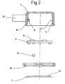
- FIG. 2 shows a schematic sectional view of the rain sensor 4 according to the invention in an exploded view.
- a board 8 against a shoulder 14 inside the housing 6 can be inserted, are mounted on the electronic and optoelectronic devices, for example in SMD (surface mounted device) technology.
- SMD surface mounted device
- the board 8 in the housing 6 it lies against the shoulder 14 in the housing after it has been pressed when inserting over the circumferential groove 12. This holds the board 8 firmly and prevents them from falling down.
- the protruding into the housing 6 in the connector pins 16 can be seen, which are connected, for example, with a partial soldering or the like with the appropriate tracks of the board 8. Also possible is a conductive press connection.
- LED or LED 15 As a component, for example, mounted on the top of the Patine 8 LED or LED 15 is required to emit visible or infrared light in the form of a directed light beam.
- the light beam impinges on the windshield 2 at an acute angle and is normally completely reflected due to its refractive index at its outer boundary to the air and strikes almost completely as a reflected portion on a photodiode, which is also mounted at a suitable location on the upper side of the board 8 , If, at the location of the reflection of the light beam, there is now a drop of water on the outside of the windscreen 2, this results at the outer interface of the disc to the air, a changed refractive behavior, whereby the light beam is not fully reflected at the interface, but a leaking outward scattered proportion arises.
- the thereby attenuated signal of the reflected portion can be detected by the photodiode and evaluated quantitatively and thus detected as a moisture curtain or rain outside on the windshield 2 of the motor vehicle.
- the desired focusing of the light beam or the reflected portion can be conveniently achieved by a suitably shaped Lichtleitmaschine 10, consisting of a highly transparent and good injection moldable plastic such as PMMA (polymethylmethacrylate), which also forms the base of the housing 6 and flat over a transparent adhesive film 36 is connected to the windshield 2.
- a suitably shaped Lichtleitmaschine 10 consisting of a highly transparent and good injection moldable plastic such as PMMA (polymethylmethacrylate), which also forms the base of the housing 6 and flat over a transparent adhesive film 36 is connected to the windshield 2.
- PMMA polymethylmethacrylate
- the light guide 10 can receive molded lens-like structures, which ensure the desired focusing and focusing of the light emitted by the LED 15 and the light components detected by the photodiode.
- an ambient light sensor 22 is further arranged to detect the incident from the outside through the windshield 2 of the motor vehicle ambient light in its brightness and a dependent control signal for automatic Can generate light control or for a day / night switching the wiper control in the motor vehicle.
- the ambient light sensor 22 preferably responds to certain portions of UV light that occur only in natural sunlight so as to preclude inadvertent shutdown of the vehicle headlamps in brightly lit tunnels or underpasses with strong artificial light sources.
- the light guide body 10 may be made of black PMMA and may contain only a small spot for the ambient light sensor 22 of clear material.
- the transparent adhesive film 36 which produces a surface connection to the windshield 2, wherein in the FIG. 2 an additional peelable protective film 3 on the transparent adhesive film 36 can be seen.
- the rain sensor 4 can be easily glued to the desired location on the windshield 2.
- the protective film 3 serves to protect the optical fiber 10 and the adhesive film 26 during transport, assembly or the like from mechanical damage.
- FIG. 4 shows, once again, the optical waveguide 10 with the focusing structures (converging lenses) introduced therein in the injection molding process in a perspective view.
- focusing structures converging lenses
Landscapes
- Engineering & Computer Science (AREA)
- Automation & Control Theory (AREA)
- Mechanical Engineering (AREA)
- Investigating Or Analysing Materials By Optical Means (AREA)
Claims (17)
- Détecteur de pluie, en particulier pour véhicules automobiles, qui présente un parcours de mesure doté d'au moins un émetteur et d'au moins un récepteur d'ondes électromagnétiques et dans lequel est disposée une vitre de pare-brise qui agit sur la propagation des ondes entre le ou les émetteurs et le ou les récepteurs de telle sorte qu'un signal de sortie détecté par le récepteur se modifie lorsqu'il se forme une couche sur la vitre de pare-brise, en particulier lorsqu'elle est mouillée par des précipitations, les composants optiques et électroniques du détecteur de pluie (4) étant montés dans un boîtier (6) et une carte (8) pouvant être placée contre un appendice (14) situé à l'intérieur du boîtier (6) et sur lequel sont montés les composants électroniques et optoélectroniques, caractérisé en ce que
le corps (10) de guidage de lumière est constitué d'une pièce en matière synthétique obtenue par une opération d'injection en deux couleurs ou par la combinaison de deux matières synthétiques monochromes. - Détecteur de pluie selon la revendication 1, caractérisé en ce que le corps (10) de guidage de lumière forme une plaque de base du boîtier (6) reliée à plat à la vitre (2) du pare-brise.
- Détecteur de pluie selon la revendication 2, caractérisé en ce que tous les composants optiques et électroniques du détecteur de pluie (4) sont montés sur une carte commune (8) par une technique SMD.
- Détecteur de pluie selon la revendication 3, caractérisé en ce que le détecteur de pluie (4) est monté dans un boîtier (6) de forme parallélépipédique et doté d'une fiche (38) intégrée qui assure son raccordement électrique à une unité d'évaluation raccordée en aval.
- Détecteur de pluie selon la revendication 4, caractérisé en ce que la carte (8) est reliée par des tiges de contact à la fiche (38) prévue sur le boîtier (6).
- Détecteur de pluie selon la revendication 7, caractérisé en ce que le détecteur de pluie (4) est collé par l'intérieur sur la vitre (2) du pare-brise.
- Détecteur de pluie selon la revendication 6, caractérisé en ce qu'un film transparent et autocollant double face (36) est prévu comme liaison entre la vitre (2) du pare-brise et le corps (10) de guidage de lumière du détecteur de pluie (4).
- Détecteur de pluie selon l'une des revendications précédentes, caractérisé en ce qu'un signal de sortie du détecteur de pluie (4) contient pour une unité d'évaluation raccordée en aval des informations concernant le degré de mouillage de la vitre (2) du pare-brise à tout instant.
- Détecteur de pluie selon la revendication 8, caractérisé en ce qu'un dispositif d'essuie-glace et/ou un éclairage du véhicule peuvent être commandés en fonction des signaux de sortie du détecteur de pluie (4).
- Détecteur de pluie selon l'une des revendications précédentes, caractérisé en ce que le ou les émetteurs est/sont une/des LED (15).
- Détecteur de pluie selon la revendication 10, caractérisé en ce que le premier récepteur qui détecte le signal optique émis par la ou les LED (15) est une photodiode.
- Détecteur de pluie selon l'une des revendications précédentes, caractérisé en ce que le deuxième récepteur est au moins une sonde (22) de lumière de l'environnement.
- Détecteur de pluie selon l'une des revendications précédentes, caractérisé en ce que la sonde (22) de lumière de l'environnement présente un angle d'ouverture d'environ 40° dont la direction d'ouverture est orientée obliquement vers le haut dans la direction d'avancement du véhicule.
- Détecteur de pluie selon l'une des revendications 12 ou 13, caractérisé en ce que la ou les sondes (22) de lumière de l'environnement est/sont sensibles à la lumière ultraviolette et en particulier à la lumière solaire.
- Détecteur de pluie selon l'une des revendications précédentes, caractérisé en ce que lorsque l'on utilise de la lumière infrarouge (IR), le corps (10) de guidage de lumière qui assure la fonction de détection de pluie est constitué de matière synthétique noire.
- Détecteur de pluie selon l'une des revendications précédentes, caractérisé en ce que des parties optiques en matière synthétique transparente (limpide) sont prévues pour le ou les récepteurs (20) dans le corps (10) de guidage de lumière.
- Détecteur de pluie selon l'une des revendications précédentes, caractérisé en ce que le corps (10) de guidage de lumière est doté de structures de lentille intégrées qui forment des faisceaux de lumière.
Applications Claiming Priority (3)
| Application Number | Priority Date | Filing Date | Title |
|---|---|---|---|
| DE19815749 | 1998-04-08 | ||
| EP03025962A EP1398231A3 (fr) | 1998-10-12 | 1999-01-08 | Capteur de pluie |
| EP99906031A EP1068112B2 (fr) | 1998-04-08 | 1999-01-08 | Detecteur de pluie |
Related Parent Applications (3)
| Application Number | Title | Priority Date | Filing Date |
|---|---|---|---|
| EP03025962A Division EP1398231A3 (fr) | 1998-04-08 | 1999-01-08 | Capteur de pluie |
| EP99906031.2 Division | 1999-01-08 | ||
| EP03025962.6 Division | 2003-11-13 |
Publications (3)
| Publication Number | Publication Date |
|---|---|
| EP1908652A2 EP1908652A2 (fr) | 2008-04-09 |
| EP1908652A3 EP1908652A3 (fr) | 2008-09-03 |
| EP1908652B1 true EP1908652B1 (fr) | 2011-01-05 |
Family
ID=7863994
Family Applications (1)
| Application Number | Title | Priority Date | Filing Date |
|---|---|---|---|
| EP08001115A Expired - Lifetime EP1908652B1 (fr) | 1998-04-08 | 1999-01-08 | Détecteur de pluie |
Country Status (2)
| Country | Link |
|---|---|
| EP (1) | EP1908652B1 (fr) |
| DE (2) | DE19846968A1 (fr) |
Families Citing this family (7)
| Publication number | Priority date | Publication date | Assignee | Title |
|---|---|---|---|---|
| DE10129038A1 (de) | 2001-06-15 | 2002-12-19 | Bosch Gmbh Robert | Regensensor, insbesondere für ein Kraftfahrzeug, sowie Verfahren zur Montage eines Regensensors |
| DE10261102A1 (de) | 2002-12-20 | 2004-07-01 | Robert Bosch Gmbh | Regensensor, insbesondere für ein Kraftfahrzeug und Verfahren zu dessen Herstellung |
| DE10261246A1 (de) * | 2002-12-20 | 2004-07-01 | Robert Bosch Gmbh | Regensensor, insbesondere für ein Kraftfahrzeug |
| DE10328468B4 (de) * | 2003-06-25 | 2017-06-08 | Kronowetter Kunststoff- Und Metalltechnik Gmbh | Spiegelklebeplatte zur Befestigung eines Innenspiegels an einer Fensterscheibe eines Kraftfahrzeugs |
| DE10360826A1 (de) * | 2003-12-23 | 2005-07-28 | Link Gmbh | Klebefolie |
| KR100981217B1 (ko) * | 2008-06-12 | 2010-09-10 | 한국오므론전장주식회사 | 컴팩트 레인 센서 |
| CN113602231A (zh) * | 2021-07-19 | 2021-11-05 | 孝感华工高理电子有限公司 | 一种汽车多功能光传感器及其使用方法 |
Family Cites Families (2)
| Publication number | Priority date | Publication date | Assignee | Title |
|---|---|---|---|---|
| DE4202121C1 (en) * | 1992-01-27 | 1992-12-24 | Leopold Kostal Gmbh & Co Kg, 5880 Luedenscheid, De | Sensor assembly detecting wetness of motor vehicle windscreen - includes receiver for radiation reflected from precipitation esp. drops of rain |
| FR2722291B1 (fr) | 1994-07-06 | 1996-10-04 | Valeo Electronique | Dispositif pour la detection d'un etat de surface d'une vitre de vehicule, et notamment pour la detection de las presence de gouttes d'eau sur un pare-brise |
-
1998
- 1998-10-12 DE DE19846968A patent/DE19846968A1/de not_active Ceased
-
1999
- 1999-01-08 EP EP08001115A patent/EP1908652B1/fr not_active Expired - Lifetime
- 1999-01-08 DE DE59915236T patent/DE59915236D1/de not_active Expired - Lifetime
Also Published As
| Publication number | Publication date |
|---|---|
| EP1908652A3 (fr) | 2008-09-03 |
| EP1908652A2 (fr) | 2008-04-09 |
| DE19846968A1 (de) | 1999-10-14 |
| DE59915236D1 (de) | 2011-02-17 |
Similar Documents
| Publication | Publication Date | Title |
|---|---|---|
| DE19861428B4 (de) | Optischer Sensor | |
| EP1068112B2 (fr) | Detecteur de pluie | |
| EP1424252B1 (fr) | Capteur optique | |
| EP1289796B1 (fr) | Unite de detection photosensible, notamment pour la commutation automatique de dispositifs d'eclairage | |
| EP1991443B1 (fr) | Ensemble caméra pour véhicule à moteur | |
| EP2452213B1 (fr) | Module optique destiné à la focalisation simultanée de deux champs de vision | |
| EP0679130B1 (fr) | Capteur pour la detection du niveau d'humidification et/ou d'encrassement des vitres, en particulier du pare-brise de vehicules a moteur | |
| EP1101673B1 (fr) | Capteur et méthode de fabrication d'un capteur | |
| DE19846969A1 (de) | Regensensor | |
| EP1200286B1 (fr) | Unite de detecteur photosensible, en particulier pour la connexion automatique de dispositifs d'eclairage | |
| EP1908652B1 (fr) | Détecteur de pluie | |
| DE10308703A1 (de) | Kraftfahrzeugscheinwerfer | |
| DE4343474A1 (de) | Sensoreinrichtung zur Erfassung des Benetzungs- und/oder Verschmutzungsgrades von Scheiben, insbesondere Frontscheiben von Kraftfahrzeugen | |
| EP0857611B1 (fr) | Dispositif de détection et procédé pour commander automatiquement l'éclairage d'un véhicule | |
| DE10033609A1 (de) | Vorrichtung sowie Verfahren zur selbsttätigen Adaption einer Lichtsensorik an eine Windschutzscheibe | |
| DE29924958U1 (de) | Optischer Sensor | |
| DE10034555A1 (de) | Lichtempfindliche Sensoreinheit, insbesondere zum automatischen Schalten von Beleuchtungseinrichtungen | |
| DE10261244A1 (de) | Regensensor, insbesondere für ein Kraftfahrzeug | |
| EP1398231A2 (fr) | Capteur de pluie | |
| DE10001705A1 (de) | Sensor zur Detektion von Feuchtigkeitstropfen und/oder Festkörperpartikeln auf einer Scheibe | |
| DE10239839A1 (de) | Aussenrückspiegel für Fahrzeuge mit einer Signalleuchte | |
| DE10261923A1 (de) | Sensorvorrichtung zur Erfassung der Benetzung einer transparenten Scheibe | |
| EP1431145A1 (fr) | Capteur de pluie, en particulier pour un véhicule automobile | |
| DE102005055306A1 (de) | Vorrichtung zur Erfassung von Umgebungs- und Vorfeldlicht in einem Kraftfahrzeug | |
| EP0857610A2 (fr) | Dispositif de détection pour commander automatiquement l'éclairage d'un véhicule |
Legal Events
| Date | Code | Title | Description |
|---|---|---|---|
| PUAI | Public reference made under article 153(3) epc to a published international application that has entered the european phase |
Free format text: ORIGINAL CODE: 0009012 |
|
| AC | Divisional application: reference to earlier application |
Ref document number: 1398231 Country of ref document: EP Kind code of ref document: P Ref document number: 1068112 Country of ref document: EP Kind code of ref document: P |
|
| AK | Designated contracting states |
Kind code of ref document: A2 Designated state(s): DE FR GB IT SE |
|
| PUAL | Search report despatched |
Free format text: ORIGINAL CODE: 0009013 |
|
| AK | Designated contracting states |
Kind code of ref document: A3 Designated state(s): DE FR GB IT SE |
|
| 17P | Request for examination filed |
Effective date: 20090303 |
|
| AKX | Designation fees paid |
Designated state(s): DE FR GB IT SE |
|
| 17Q | First examination report despatched |
Effective date: 20090417 |
|
| GRAP | Despatch of communication of intention to grant a patent |
Free format text: ORIGINAL CODE: EPIDOSNIGR1 |
|
| GRAS | Grant fee paid |
Free format text: ORIGINAL CODE: EPIDOSNIGR3 |
|
| GRAA | (expected) grant |
Free format text: ORIGINAL CODE: 0009210 |
|
| AC | Divisional application: reference to earlier application |
Ref document number: 1068112 Country of ref document: EP Kind code of ref document: P Ref document number: 1398231 Country of ref document: EP Kind code of ref document: P |
|
| AK | Designated contracting states |
Kind code of ref document: B1 Designated state(s): DE FR GB IT SE |
|
| REG | Reference to a national code |
Ref country code: GB Ref legal event code: FG4D Free format text: NOT ENGLISH |
|
| REF | Corresponds to: |
Ref document number: 59915236 Country of ref document: DE Date of ref document: 20110217 Kind code of ref document: P |
|
| REG | Reference to a national code |
Ref country code: DE Ref legal event code: R096 Ref document number: 59915236 Country of ref document: DE Effective date: 20110217 |
|
| REG | Reference to a national code |
Ref country code: SE Ref legal event code: TRGR |
|
| PLBE | No opposition filed within time limit |
Free format text: ORIGINAL CODE: 0009261 |
|
| STAA | Information on the status of an ep patent application or granted ep patent |
Free format text: STATUS: NO OPPOSITION FILED WITHIN TIME LIMIT |
|
| 26N | No opposition filed |
Effective date: 20111006 |
|
| REG | Reference to a national code |
Ref country code: DE Ref legal event code: R097 Ref document number: 59915236 Country of ref document: DE Effective date: 20111006 |
|
| REG | Reference to a national code |
Ref country code: FR Ref legal event code: PLFP Year of fee payment: 18 |
|
| PGFP | Annual fee paid to national office [announced via postgrant information from national office to epo] |
Ref country code: IT Payment date: 20160122 Year of fee payment: 18 |
|
| PGFP | Annual fee paid to national office [announced via postgrant information from national office to epo] |
Ref country code: GB Payment date: 20160122 Year of fee payment: 18 Ref country code: SE Payment date: 20160121 Year of fee payment: 18 Ref country code: FR Payment date: 20160121 Year of fee payment: 18 |
|
| REG | Reference to a national code |
Ref country code: DE Ref legal event code: R084 Ref document number: 59915236 Country of ref document: DE |
|
| PGFP | Annual fee paid to national office [announced via postgrant information from national office to epo] |
Ref country code: DE Payment date: 20170329 Year of fee payment: 19 |
|
| GBPC | Gb: european patent ceased through non-payment of renewal fee |
Effective date: 20170108 |
|
| REG | Reference to a national code |
Ref country code: FR Ref legal event code: ST Effective date: 20170929 |
|
| PG25 | Lapsed in a contracting state [announced via postgrant information from national office to epo] |
Ref country code: FR Free format text: LAPSE BECAUSE OF NON-PAYMENT OF DUE FEES Effective date: 20170131 |
|
| PG25 | Lapsed in a contracting state [announced via postgrant information from national office to epo] |
Ref country code: SE Free format text: LAPSE BECAUSE OF NON-PAYMENT OF DUE FEES Effective date: 20170109 Ref country code: GB Free format text: LAPSE BECAUSE OF NON-PAYMENT OF DUE FEES Effective date: 20170108 |
|
| PG25 | Lapsed in a contracting state [announced via postgrant information from national office to epo] |
Ref country code: IT Free format text: LAPSE BECAUSE OF NON-PAYMENT OF DUE FEES Effective date: 20170108 |
|
| REG | Reference to a national code |
Ref country code: DE Ref legal event code: R119 Ref document number: 59915236 Country of ref document: DE |
|
| PG25 | Lapsed in a contracting state [announced via postgrant information from national office to epo] |
Ref country code: DE Free format text: LAPSE BECAUSE OF NON-PAYMENT OF DUE FEES Effective date: 20180801 |