EP1908652B1 - Rain sensor - Google Patents
Rain sensor Download PDFInfo
- Publication number
- EP1908652B1 EP1908652B1 EP08001115A EP08001115A EP1908652B1 EP 1908652 B1 EP1908652 B1 EP 1908652B1 EP 08001115 A EP08001115 A EP 08001115A EP 08001115 A EP08001115 A EP 08001115A EP 1908652 B1 EP1908652 B1 EP 1908652B1
- Authority
- EP
- European Patent Office
- Prior art keywords
- rain sensor
- sensor according
- windscreen
- light
- housing
- Prior art date
- Legal status (The legal status is an assumption and is not a legal conclusion. Google has not performed a legal analysis and makes no representation as to the accuracy of the status listed.)
- Expired - Lifetime
Links
- 230000003287 optical effect Effects 0.000 claims description 12
- 229920003023 plastic Polymers 0.000 claims description 9
- 239000004033 plastic Substances 0.000 claims description 8
- 238000001746 injection moulding Methods 0.000 claims description 5
- 239000000853 adhesive Substances 0.000 claims description 4
- 238000011156 evaluation Methods 0.000 claims description 4
- 230000005693 optoelectronics Effects 0.000 claims description 4
- 238000005516 engineering process Methods 0.000 claims description 2
- 238000009736 wetting Methods 0.000 claims 2
- 239000011248 coating agent Substances 0.000 claims 1
- 238000000576 coating method Methods 0.000 claims 1
- 238000001556 precipitation Methods 0.000 claims 1
- 239000002313 adhesive film Substances 0.000 description 6
- 230000001681 protective effect Effects 0.000 description 4
- 238000004026 adhesive bonding Methods 0.000 description 2
- 230000001419 dependent effect Effects 0.000 description 2
- 238000002347 injection Methods 0.000 description 2
- 239000007924 injection Substances 0.000 description 2
- 238000009434 installation Methods 0.000 description 2
- 238000000034 method Methods 0.000 description 2
- 239000013307 optical fiber Substances 0.000 description 2
- 108090000623 proteins and genes Proteins 0.000 description 2
- 230000001154 acute effect Effects 0.000 description 1
- 230000001070 adhesive effect Effects 0.000 description 1
- 230000002238 attenuated effect Effects 0.000 description 1
- 238000010276 construction Methods 0.000 description 1
- 230000008878 coupling Effects 0.000 description 1
- 238000010168 coupling process Methods 0.000 description 1
- 238000005859 coupling reaction Methods 0.000 description 1
- 230000005670 electromagnetic radiation Effects 0.000 description 1
- 239000000463 material Substances 0.000 description 1
- 239000002184 metal Substances 0.000 description 1
- 238000000465 moulding Methods 0.000 description 1
- 229920003229 poly(methyl methacrylate) Polymers 0.000 description 1
- 239000004926 polymethyl methacrylate Substances 0.000 description 1
- 238000007493 shaping process Methods 0.000 description 1
- 238000005476 soldering Methods 0.000 description 1
- 230000000007 visual effect Effects 0.000 description 1
- XLYOFNOQVPJJNP-UHFFFAOYSA-N water Substances O XLYOFNOQVPJJNP-UHFFFAOYSA-N 0.000 description 1
- 238000003466 welding Methods 0.000 description 1
Images


Classifications
-
- B—PERFORMING OPERATIONS; TRANSPORTING
- B60—VEHICLES IN GENERAL
- B60S—SERVICING, CLEANING, REPAIRING, SUPPORTING, LIFTING, OR MANOEUVRING OF VEHICLES, NOT OTHERWISE PROVIDED FOR
- B60S1/00—Cleaning of vehicles
- B60S1/02—Cleaning windscreens, windows or optical devices
- B60S1/04—Wipers or the like, e.g. scrapers
- B60S1/06—Wipers or the like, e.g. scrapers characterised by the drive
- B60S1/08—Wipers or the like, e.g. scrapers characterised by the drive electrically driven
- B60S1/0818—Wipers or the like, e.g. scrapers characterised by the drive electrically driven including control systems responsive to external conditions, e.g. by detection of moisture, dirt or the like
- B60S1/0822—Wipers or the like, e.g. scrapers characterised by the drive electrically driven including control systems responsive to external conditions, e.g. by detection of moisture, dirt or the like characterized by the arrangement or type of detection means
- B60S1/0833—Optical rain sensor
-
- B—PERFORMING OPERATIONS; TRANSPORTING
- B60—VEHICLES IN GENERAL
- B60S—SERVICING, CLEANING, REPAIRING, SUPPORTING, LIFTING, OR MANOEUVRING OF VEHICLES, NOT OTHERWISE PROVIDED FOR
- B60S1/00—Cleaning of vehicles
- B60S1/02—Cleaning windscreens, windows or optical devices
- B60S1/04—Wipers or the like, e.g. scrapers
- B60S1/06—Wipers or the like, e.g. scrapers characterised by the drive
- B60S1/08—Wipers or the like, e.g. scrapers characterised by the drive electrically driven
- B60S1/0818—Wipers or the like, e.g. scrapers characterised by the drive electrically driven including control systems responsive to external conditions, e.g. by detection of moisture, dirt or the like
- B60S1/0822—Wipers or the like, e.g. scrapers characterised by the drive electrically driven including control systems responsive to external conditions, e.g. by detection of moisture, dirt or the like characterized by the arrangement or type of detection means
- B60S1/0874—Wipers or the like, e.g. scrapers characterised by the drive electrically driven including control systems responsive to external conditions, e.g. by detection of moisture, dirt or the like characterized by the arrangement or type of detection means characterized by the position of the sensor on the windshield
- B60S1/0888—Wipers or the like, e.g. scrapers characterised by the drive electrically driven including control systems responsive to external conditions, e.g. by detection of moisture, dirt or the like characterized by the arrangement or type of detection means characterized by the position of the sensor on the windshield characterized by the attachment of the elements in a unit
-
- B—PERFORMING OPERATIONS; TRANSPORTING
- B60—VEHICLES IN GENERAL
- B60S—SERVICING, CLEANING, REPAIRING, SUPPORTING, LIFTING, OR MANOEUVRING OF VEHICLES, NOT OTHERWISE PROVIDED FOR
- B60S1/00—Cleaning of vehicles
- B60S1/02—Cleaning windscreens, windows or optical devices
- B60S1/04—Wipers or the like, e.g. scrapers
- B60S1/06—Wipers or the like, e.g. scrapers characterised by the drive
- B60S1/08—Wipers or the like, e.g. scrapers characterised by the drive electrically driven
- B60S1/0818—Wipers or the like, e.g. scrapers characterised by the drive electrically driven including control systems responsive to external conditions, e.g. by detection of moisture, dirt or the like
- B60S1/0822—Wipers or the like, e.g. scrapers characterised by the drive electrically driven including control systems responsive to external conditions, e.g. by detection of moisture, dirt or the like characterized by the arrangement or type of detection means
- B60S1/0862—Wipers or the like, e.g. scrapers characterised by the drive electrically driven including control systems responsive to external conditions, e.g. by detection of moisture, dirt or the like characterized by the arrangement or type of detection means including additional sensors
- B60S1/087—Wipers or the like, e.g. scrapers characterised by the drive electrically driven including control systems responsive to external conditions, e.g. by detection of moisture, dirt or the like characterized by the arrangement or type of detection means including additional sensors including an ambient light sensor
Definitions
- the invention relates to a rain sensor with the features mentioned in the preamble of claim 1.
- the optical rain sensor usually comprises a light source whose electromagnetic radiation from the windshield, depending on the moisture content on the windshield is reflected differently. The reflected portion is detected by means of a photoelement so that an output signal of the rain sensor corresponding to the moisture pad can be provided. These output signals can be evaluated and used to control the windshield wiper, that both the switch-on and the wiper speed is varied in dependence on a measured amount of rain.
- Known rain sensors are usually mounted on the inside of the windshield, preferably behind an interior rearview mirror. To attach, for example, glued metal feet are used. Next to it are also known fortifications on an additional frame, which is previously connected to the disc and in the later rain sensor housing is pressed.
- the rain sensor according to the invention with the features mentioned in claim 1 has in particular the advantage that essentially only three parts are required for its construction.
- the rain sensor consists essentially of a housing, from which the electrical leads are led out for connection to a downstream evaluation, a circuit board or board and a light guide, which preferably already has all the necessary optical lens structures.
- This provides a low cost, very compact and easy to install rain sensor.
- a transparent film which is preferably self-adhesive on both sides, a simple installation of the rain sensor can be achieved without affecting its optical properties.
- the rain sensor can be produced with a few assembly steps, so that it can be mass-produced inexpensively.
- the light guide body simultaneously forms the cover of the sensor housing and in this way forms with this a complete electronics housing.
- the connection can be ensured in an advantageous manner by clipping.
- a peelable protective film on the outer adhesive side of the transparent adhesive film simultaneously forms a protection of the optical fiber against mechanical damage during transport. Due to the very compact design automakers are as buyers of such rain sensors in a position to make a simple and fast and therefore very cost-effective installation, which also can be easily automated.
- An output signal of the rain sensor according to the invention can be used in an advantageous manner for driving a windshield wiper device and / or a vehicle lighting. So it may be useful, for example, in heavy rain or fog, automatically turn on additional fog lights.
- a brightness sensor for ambient light in addition to the rain sensor, can additionally be integrated, which supplies a largely influenced by daylight signal and accordingly has a relatively wide and upward opening cone for incident light. It is also advantageous if the brightness sensor is sensitive to ultraviolet light components, as they occur in sunlight, but not in artificial light. In this way, a false triggering by strong artificial light, for example in a tunnel passage, can be avoided.
- the focusing of the incident light can be carried out in an advantageous manner by the light guide, which also acts as a base plate for the sensor housing.
- a light-conducting body can be produced, for example, from a plastic such as PMMA (polymethylmetachrylate) by injection molding, wherein optical structures such as converging lenses can be incorporated in a simple manner in the molding process.
- PMMA polymethylmetachrylate
- FIG. 1a shows a schematic side view of a rain sensor 4 according to the invention, which is fastened on the inside to a windshield 2 of a motor vehicle.
- the electronic and optoelectronic components of the rain sensor 4 are enclosed by a housing 6, which is opaque to the inside, that is to the passenger compartment, opaque.
- the housing bottom which forms a planar connection to the windshield 2, represents a Lichtleit body 10, in which all the optical structures required for the function (lens structures, Lichtleit Genevaen and the like) are introduced. This can be done for example by an injection molding of a suitable optically transparent plastic.
- For mechanical and optical coupling of the rain sensor 4 with the windshield of the light guide 10 is connected via a double-sided self-adhesive transparent adhesive film 36 to the windshield 2.
- FIG. 1b shows a schematic plan view of the rain sensor 4 according to Figure la. Visible here is a plug 38 for electrical connection to a downstream, but not shown here, evaluation. This can variably control a windshield wiper device and / or a vehicle lighting based on the signals supplied by the rain sensor 4. Depending on the embodiment, the plug 38 can have four or for example eight plug pins which protrude into a mounted circuit board in the housing 6 and are soldered or pressed there to produce an electrical connection.
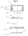
- FIG. 2 shows a schematic sectional view of the rain sensor 4 according to the invention in an exploded view.
- a board 8 against a shoulder 14 inside the housing 6 can be inserted, are mounted on the electronic and optoelectronic devices, for example in SMD (surface mounted device) technology.
- SMD surface mounted device
- the board 8 in the housing 6 it lies against the shoulder 14 in the housing after it has been pressed when inserting over the circumferential groove 12. This holds the board 8 firmly and prevents them from falling down.
- the protruding into the housing 6 in the connector pins 16 can be seen, which are connected, for example, with a partial soldering or the like with the appropriate tracks of the board 8. Also possible is a conductive press connection.
- LED or LED 15 As a component, for example, mounted on the top of the Patine 8 LED or LED 15 is required to emit visible or infrared light in the form of a directed light beam.
- the light beam impinges on the windshield 2 at an acute angle and is normally completely reflected due to its refractive index at its outer boundary to the air and strikes almost completely as a reflected portion on a photodiode, which is also mounted at a suitable location on the upper side of the board 8 , If, at the location of the reflection of the light beam, there is now a drop of water on the outside of the windscreen 2, this results at the outer interface of the disc to the air, a changed refractive behavior, whereby the light beam is not fully reflected at the interface, but a leaking outward scattered proportion arises.
- the thereby attenuated signal of the reflected portion can be detected by the photodiode and evaluated quantitatively and thus detected as a moisture curtain or rain outside on the windshield 2 of the motor vehicle.
- the desired focusing of the light beam or the reflected portion can be conveniently achieved by a suitably shaped Lichtleitmaschine 10, consisting of a highly transparent and good injection moldable plastic such as PMMA (polymethylmethacrylate), which also forms the base of the housing 6 and flat over a transparent adhesive film 36 is connected to the windshield 2.
- a suitably shaped Lichtleitmaschine 10 consisting of a highly transparent and good injection moldable plastic such as PMMA (polymethylmethacrylate), which also forms the base of the housing 6 and flat over a transparent adhesive film 36 is connected to the windshield 2.
- PMMA polymethylmethacrylate
- the light guide 10 can receive molded lens-like structures, which ensure the desired focusing and focusing of the light emitted by the LED 15 and the light components detected by the photodiode.
- an ambient light sensor 22 is further arranged to detect the incident from the outside through the windshield 2 of the motor vehicle ambient light in its brightness and a dependent control signal for automatic Can generate light control or for a day / night switching the wiper control in the motor vehicle.
- the ambient light sensor 22 preferably responds to certain portions of UV light that occur only in natural sunlight so as to preclude inadvertent shutdown of the vehicle headlamps in brightly lit tunnels or underpasses with strong artificial light sources.
- the light guide body 10 may be made of black PMMA and may contain only a small spot for the ambient light sensor 22 of clear material.
- the transparent adhesive film 36 which produces a surface connection to the windshield 2, wherein in the FIG. 2 an additional peelable protective film 3 on the transparent adhesive film 36 can be seen.
- the rain sensor 4 can be easily glued to the desired location on the windshield 2.
- the protective film 3 serves to protect the optical fiber 10 and the adhesive film 26 during transport, assembly or the like from mechanical damage.
- FIG. 4 shows, once again, the optical waveguide 10 with the focusing structures (converging lenses) introduced therein in the injection molding process in a perspective view.
- focusing structures converging lenses
Landscapes
- Engineering & Computer Science (AREA)
- Automation & Control Theory (AREA)
- Mechanical Engineering (AREA)
- Investigating Or Analysing Materials By Optical Means (AREA)
Description
Die Erfindung betrifft einen Regensensor mit den im Oberbegriff des Anspruchs 1 genannten Merkmalen.The invention relates to a rain sensor with the features mentioned in the preamble of claim 1.
Es sind Scheibenwischvorrichtungen für Windschutzscheiben von Kraftfahrzeugen bekannt, bei denen eine Steuerung der Scheibenwischer nicht nur über einen herkömmlichen Lenkstockhebel, sondern zusätzlich über einen optischen Regensensor erfolgt. Der optische Regensensor umfaßt üblicherweise eine Lichtquelle, deren elektromagnetische Strahlung von der Windschutzscheibe, je nach Feuchtigkeitsbelag auf der Windschutzscheibe unterschiedlich reflektiert wird. Der reflektierte Anteil wird mittels eines Photoelementes erfaßt, so daß ein dem Feuchtigkeitsbelag entsprechendes Ausgangssignal des Regensensors bereitgestellt werden kann. Diese Ausgangssignale können derart ausgewertet und zur Steuerung der Scheibenwischer verwendet werden, daß sowohl die Einschaltung als auch die Wischergeschwindigkeit in Abhängigkeit von einer gemessenen Regenmenge variiert wird.There are windshield wiper devices for windshields of motor vehicles are known in which a control of the windshield wiper not only via a conventional steering column lever, but also via an optical rain sensor. The optical rain sensor usually comprises a light source whose electromagnetic radiation from the windshield, depending on the moisture content on the windshield is reflected differently. The reflected portion is detected by means of a photoelement so that an output signal of the rain sensor corresponding to the moisture pad can be provided. These output signals can be evaluated and used to control the windshield wiper, that both the switch-on and the wiper speed is varied in dependence on a measured amount of rain.
Bekannte Regensensoren werden üblicherweise innen an der Windschutzscheibe angebracht, vorzugsweise hinter einem Innenrückspiegel. Zur Befestigung werden beispielsweise geklebte Metallfüße verwendet. Bekannt sind daneben auch Befestigungen über einen zusätzlichen Rahmen, der zuvor mit der Scheibe verbunden wird und in den später das Regensensorgehäuse eingedrückt wird.Known rain sensors are usually mounted on the inside of the windshield, preferably behind an interior rearview mirror. To attach, for example, glued metal feet are used. Next to it are also known fortifications on an additional frame, which is previously connected to the disc and in the later rain sensor housing is pressed.
Aus der
Der erfindungsgemäße Regensensor mit den im Anspruch 1 genannten Merkmalen weist insbesondere den Vorteil auf, dass im wesentlichen nur drei Einzelteile zu seinem Aufbau erforderlich sind. Der Regensensor besteht im wesentlichen aus einem Gehäuse, aus dem die elektrischen Leitungen zur Verbindung mit einer nachgeschalteten Auswerteeinheit herausgeführt sind, einer Leiterplatte beziehungsweise Platine sowie einem Lichtleitkörper, der vorzugsweise bereits über alle notwendigen optischen Linsenstrukturen verfügt. Dadurch wird ein kostengünstiger, sehr kompakter und einfach zu montierender Regensensor bereitgestellt. Insbesondere über eine transparente Folie, die vorzugsweise beidseitig selbstklebend ist, lässt sich eine einfache Montage des Regensensors erreichen, ohne dass dessen optische Eigenschaften beeinträchtigt werden. Ferner lässt sich der Regensensor mit wenigen Montageschritten herstellen, so dass dieser kostengünstig in Massenfertigung produzierbar ist.The rain sensor according to the invention with the features mentioned in claim 1 has in particular the advantage that essentially only three parts are required for its construction. The rain sensor consists essentially of a housing, from which the electrical leads are led out for connection to a downstream evaluation, a circuit board or board and a light guide, which preferably already has all the necessary optical lens structures. This provides a low cost, very compact and easy to install rain sensor. In particular, a transparent film, which is preferably self-adhesive on both sides, a simple installation of the rain sensor can be achieved without affecting its optical properties. Furthermore, the rain sensor can be produced with a few assembly steps, so that it can be mass-produced inexpensively.
Durch eine Montage aller erforderlichen elektronischen und optoelektronischen Bauteile auf einer gemeinsamen Platine, vorzugsweise in SMD-(Surface Mounted Device)-Technik bestückt, lassen sich sehr kompakte Sensoren realisieren, die sich zudem im Fahrzeug problemlos montieren lassen. So kann ein derartiger Regensensor deutlich kompakter ausgeführt sein als bekannte Regensensoren und wie diese beispielsweise hinter einem Innenrückspiegel an der Innenseite der Windschutzscheibe montiert sein.By mounting all the necessary electronic and optoelectronic components on a common board, preferably in SMD (Surface Mounted Device) equipped, very compact sensors can be realized, which can also be easily installed in the vehicle. Thus, such a rain sensor can be made significantly more compact than known rain sensors and how they can be mounted, for example, behind an interior rearview mirror on the inside of the windshield.
In bevorzugter Ausgestaltung der Erfindung bildet der Lichtleitkörper gleichzeitig den Deckel des Sensorgehäuses und bildet auf diese Weise mit diesem ein komplettes Elektronikgehäuse. Die Verbindung kann in vorteilhafter Weise durch Verklipsen sichergestellt werden. Eine abziehbare Schutzfolie auf äußerer Klebeseite der transparenten Klebefolie bildet gleichzeitig einen Schutz des Lichtleitkörpers gegen mechanische Beschädigung bereits beim Transport. Durch den sehr kompakten Aufbau sind Autohersteller als Abnehmer derartiger Regensensoren in die Lage versetzt, eine einfache und schnelle und damit sehr kostengünstige Montage vornehmen zu können, die sich zudem problemlos automatisieren läßt.In a preferred embodiment of the invention, the light guide body simultaneously forms the cover of the sensor housing and in this way forms with this a complete electronics housing. The connection can be ensured in an advantageous manner by clipping. A peelable protective film on the outer adhesive side of the transparent adhesive film simultaneously forms a protection of the optical fiber against mechanical damage during transport. Due to the very compact design automakers are as buyers of such rain sensors in a position to make a simple and fast and therefore very cost-effective installation, which also can be easily automated.
Ein Ausgangssignal des erfindungsgemäßen Regensensors läßt sich in vorteilhafter Weise zur Ansteuerung einer Scheibenwischvorrichtung und/oder einer Fahrzeugbeleuchtung einsetzen. So kann es beispielsweise bei stärkerem Regen oder bei Nebel sinnvoll sein, zusätzliche Nebelscheinwerfer automatisch einzuschalten.An output signal of the rain sensor according to the invention can be used in an advantageous manner for driving a windshield wiper device and / or a vehicle lighting. So it may be useful, for example, in heavy rain or fog, automatically turn on additional fog lights.
In einer bevorzugten Ausgestaltung der Erfindung kann neben dem Regensensor zusätzlich ein Helligkeitssensor für Umgebungslicht integriert sein, der ein weitgehend vom Tageslicht beeinflußtes Signal liefert und dementsprechend einen relativ weiten und nach oben gerichteten Öffnungskegel für einfallendes Licht aufweist. Vorteilhaft ist weiterhin, wenn der Helligkeitssensor empfindlich ist auf ultraviolette Lichtanteile, wie sie im Sonnenlicht, nicht jedoch bei künstlichem Licht, vorkommen. Auf diese Weise kann eine Fehlauslösung durch starkes künstliches Licht, beispielsweise bei einer Tunneldurchfahrt, vermieden werden.In a preferred embodiment of the invention, in addition to the rain sensor, a brightness sensor for ambient light can additionally be integrated, which supplies a largely influenced by daylight signal and accordingly has a relatively wide and upward opening cone for incident light. It is also advantageous if the brightness sensor is sensitive to ultraviolet light components, as they occur in sunlight, but not in artificial light. In this way, a false triggering by strong artificial light, for example in a tunnel passage, can be avoided.
Die Fokussierung des einfallenden Lichts kann in vorteilhafter Weise durch den Lichtleitkörper erfolgen, der gleichzeitig als Grundplatte für das Sensorgehäuse fungiert. Ein solcher Lichtleitkörper kann beispielsweise aus einem Kunststoff wie PMMA (Polymethylmetachrylat) im Spritzgußverfahren hergestellt sein, wobei sich in einfacher Weise optische Strukturen wie Sammellinsen im Formprozeß einbringen lassen. Bei Verwendung von infrarotem Licht für die Regensensorfunktion ist es vorteilhaft, den Lichtleitkörper aus schwarzem PMMA herzustellen und lediglich den Lichtdurchtritt für den Umgebungslichtsensor aus klarem Kunststoff vorzusehen. Dies läßt sich durch Verarbeitung im sogenannten Zweifarbspritzverfahren oder auch durch Kombination, durch Verklebung oder Verschweißung, zweier einfarbiger Kunststoffteile realisieren.The focusing of the incident light can be carried out in an advantageous manner by the light guide, which also acts as a base plate for the sensor housing. Such a light-conducting body can be produced, for example, from a plastic such as PMMA (polymethylmetachrylate) by injection molding, wherein optical structures such as converging lenses can be incorporated in a simple manner in the molding process. When using infrared light for the rain sensor function, it is advantageous to produce the light guide of black PMMA and provide only the light passage for the ambient light sensor made of clear plastic. This can be realized by processing in the so-called two-color injection process or by combination, by gluing or welding, two monochrome plastic parts.
Weitere vorteilhafte Ausgestaltungen der Erfindung ergeben sich aus den übrigen, in den Unteransprüchen genannten Merkmalen.Further advantageous embodiments of the invention will become apparent from the remaining features mentioned in the dependent claims.
Die Erfindung wird nachfolgend in Ausführungsbeispielen anhand der zugehörigen Zeichnungen näher erläutert. Es zeigen:
- Figur la
- eine schematische Seitenansicht eines er- findungsgemäßen Regensensors,
- Figur 1b
- eine schematische Draufsicht auf den Re- gensensor entsprechend
Figur 1 , Figur 2- eine schematische Schnittansicht des er- findungsgemäßen Regensensors in einer Ex- plosionsdarstellung und
Figur 3- einen Lichtleitkörper in einer perspekti- vischen Darstellung.
- Figure la
- a schematic side view of a rain sensor according to the invention,
- FIG. 1b
- a schematic plan view of the gene according to gene
FIG. 1 . - FIG. 2
- a schematic sectional view of the rain sensor according to the invention in an exploded view and
- FIG. 3
- a light guide in a perspective view.
Die
Als Bauteil ist beispielsweise eine auf der Oberseite der Patine 8 montierte Leuchtdiode beziehungsweise LED 15 erforderlich, die sichtbares oder infrarotes Licht in Form eines gerichteten Lichtstrahles emittiert. Der Lichtstrahl trifft in einem spitzen Winkel auf die Windschutzscheibe 2 auf und wird aufgrund deren Brechungsindex an ihrer äußeren Grenzfläche zur Luft normalerweise vollständig reflektiert und trifft nahezu vollständig als reflektierter Anteil auf eine Photodiode, die ebenfalls an geeigneter Stelle auf der Oberseite der Platine 8 montiert ist. Befindet sich nun am Ort der Reflexion des Lichtstrahls ein Wassertropfen außen auf der Windschutzscheibe 2, resultiert an der äußeren Grenzfläche der Scheibe zur Luft ein verändertes Brechungsverhalten, wodurch der Lichtstrahl an der Grenzfläche nicht vollständig reflektiert wird, sondern ein nach außen austretender gestreuter Anteil entsteht. Das dadurch abgeschwächte Signal des reflektierten Anteiles kann von der Photodiode detektiert und quantitativ ausgewertet werden und somit als Feuchtigkeitsschleier beziehungsweise Regen außen auf der Windschutzscheibe 2 des Kraftfahrzeuges erfaßt werden.As a component, for example, mounted on the top of the
Die gewünschte Fokussierung des Lichtstrahles beziehungsweise des reflektierten Anteiles kann zweckmäßigerweise durch einen geeignet geformten Lichtleitkörper 10, bestehend aus einem hochtransparenten und gut spritzgießfähigen Kunststoff wie beispielsweise PMMA (Polymethylmetachrylat), erreicht werden, der gleichzeitig die Grundseite des Gehäuses 6 bildet und flächig über eine transparente Klebefolie 36 mit der Windschutzscheibe 2 verbunden ist. Durch geeignete Formung, vorzugsweise im Spritzgußverfahren, kann der Lichtleitkörper 10 eingeformte linsenförmige Strukturen erhalten, die für die gewünschte Fokussierung und Bündelung des von der LED 15 emittierten Lichtes sowie der von der Photodiode detektierten Lichtanteile sorgen.The desired focusing of the light beam or the reflected portion can be conveniently achieved by a suitably shaped
Auf der Platine 8 ist weiterhin ein Umgebungslichtsensor 22 angeordnet, der von außen durch die Windschutzscheibe 2 des Kraftfahrzeuges fallendes Umgebungslicht in seiner Helligkeit erfassen und ein davon abhängiges Steuersignal für eine automatische Lichtsteuerung beziehungsweise für eine Tag/Nacht-Umschaltung der Scheibenwischersteuerung im Kraftfahrzeug generieren kann. Zweckmäßigerweise reagiert der Umgebungslichtsensor 22 vorzugsweise auf bestimmte UV-Lichtanteile, die nur im natürlichen Sonnenlicht vorkommen, um auf diese Weise ein unbeabsichtigtes Abschalten der Fahrzeugscheinwerfer in hell beleuchteten Tunnels oder Unterführungen mit starken künstlichen Lichtquellen auszuschließen.On the
Bei Verwendung von infrarotem Licht für den Regensensor 4 kann der Lichtleitkörper 10 beispielsweise aus schwarzem PMMA bestehen und nur eine kleine Stelle für den Umgebungslichtsensor 22 aus klarem Material enthalten.For example, when using infrared light for the
Erkennbar ist weiterhin die transparente Klebefolie 36, die eine flächige Verbindung zur Windschutzscheibe 2 herstellt, wobei in der
Figur 4 zeigt zur Verdeutlichung nochmals den Lichtleitkörper 10 mit den darin im Spritzgießprozeß eingebrachten fokussierenden Strukturen (Sammellinsen) in einer perspektivischen Darstellung. Erkennbar sind an äußeren Rand jeweils eine längliche Nut 19, in die jeweils ein passender Steg 18 des Gehäuses 6 geklipst werden kann (
Claims (17)
- Rain sensor, in particular for motor vehicles, having a measuring section which has at least one transmitter and at least one receiver for electromagnetic waves, in which a windscreen is arranged and which influences the propagation of waves between the at least one transmitter and the at least one receiver in such a manner that, when a coating forms on the windscreen, in particular when there is wetting due to precipitation, an output signal sensed by the receiver changes, the optical and electronic components of the rain sensor (4) being mounted in a housing (6), and a printed circuit board (8) on which electronic and optoelectronic components are mounted being able to be inserted against a shoulder (14) inside the housing (6), characterized in that the light guide body (10) consists of a plastic part formed by a two-colour injection-moulding process or is produced by a combination of two single-coloured plastics.
- Rain sensor according to Claim 1, characterized in that the light guide body (10) forms a base plate of the housing (6), which base plate is connected over its surface area to the windscreen (2).
- Rain sensor according to Claim 2, characterized in that all of the optical and electronic components of the rain sensor (4) are mounted on a common printed circuit board (8) using SMD technology.
- Rain sensor according to Claim 3, characterized in that the rain sensor (4) is mounted in a cuboidal housing (6) with an integrated connector (38) for electrical connection to a downstream evaluation unit.
- Rain sensor according to Claim 4, characterized in that the printed circuit board (8) is connected to the connector (38) on the housing (6) via contact pins.
- Rain sensor according to Claim 7, characterized in that the rain sensor (4) is adhesively bonded to the windscreen (2) from the inside.
- Rain sensor according to Claim 6, characterized in that a transparent film (36) which is self-adhesive on both sides is provided as a connection between the windscreen (2) and the light guide body (10) of the rain sensor (4).
- Rain sensor according to one of the preceding claims, characterized in that an output signal from the rain sensor (4) to a downstream evaluation circuit contains information relating to an instantaneous degree of wetting of the windscreen (2).
- Rain sensor according to Claim 8, characterized in that a windscreen wiping device and/or a vehicle lighting system can be controlled on the basis of the output signals from the rain sensor (4).
- Rain sensor according to one of the preceding claims, characterized in that the at least one transmitter is an LED (15).
- Rain sensor according to Claim 10, characterized in that the first receiver which detects the optical signal emitted by the at least one LED (15) is a photodiode.
- Rain sensor according to one of the preceding claims, characterized in that at least one ambient light sensor (22) is provided as a second receiver.
- Rain sensor according to one of the preceding claims, characterized in that the ambient light sensor (22) has an acceptance angle of approximately 40° with an acceptance direction obliquely upwards in the direction of travel.
- Rain sensor according to either of Claims 12 and 13, characterized in that the at least one ambient light sensor (22) is sensitive to ultraviolet light, in particular to sunlight.
- Rain sensor according to one of the preceding claims, characterized in that, when IR (infrared) light is used, the light guide body (10) for the rain sensor function is composed of black plastic.
- Rain sensor according to one of the preceding claims, characterized in that optical regions of transparent (clear) plastic in the light guide body (10) are provided for the at least one receiver (20).
- Rain sensor according to one of the preceding claims, characterized in that the light guide body (10) is provided with inserted lens structures for focusing the light.
Applications Claiming Priority (3)
| Application Number | Priority Date | Filing Date | Title |
|---|---|---|---|
| DE19815749 | 1998-04-08 | ||
| EP03025962A EP1398231A3 (en) | 1998-10-12 | 1999-01-08 | Rain sensor |
| EP99906031A EP1068112B2 (en) | 1998-04-08 | 1999-01-08 | Rain sensor |
Related Parent Applications (3)
| Application Number | Title | Priority Date | Filing Date |
|---|---|---|---|
| EP03025962A Division EP1398231A3 (en) | 1998-04-08 | 1999-01-08 | Rain sensor |
| EP99906031.2 Division | 1999-01-08 | ||
| EP03025962.6 Division | 2003-11-13 |
Publications (3)
| Publication Number | Publication Date |
|---|---|
| EP1908652A2 EP1908652A2 (en) | 2008-04-09 |
| EP1908652A3 EP1908652A3 (en) | 2008-09-03 |
| EP1908652B1 true EP1908652B1 (en) | 2011-01-05 |
Family
ID=7863994
Family Applications (1)
| Application Number | Title | Priority Date | Filing Date |
|---|---|---|---|
| EP08001115A Expired - Lifetime EP1908652B1 (en) | 1998-04-08 | 1999-01-08 | Rain sensor |
Country Status (2)
| Country | Link |
|---|---|
| EP (1) | EP1908652B1 (en) |
| DE (2) | DE19846968A1 (en) |
Families Citing this family (7)
| Publication number | Priority date | Publication date | Assignee | Title |
|---|---|---|---|---|
| DE10129038A1 (en) | 2001-06-15 | 2002-12-19 | Bosch Gmbh Robert | Rain sensor for cars, has electrostatic protective screen |
| DE10261102A1 (en) | 2002-12-20 | 2004-07-01 | Robert Bosch Gmbh | Rain sensor, in particular for a motor vehicle and method for its production |
| DE10261246A1 (en) * | 2002-12-20 | 2004-07-01 | Robert Bosch Gmbh | Rain sensor, especially for a motor vehicle |
| DE10328468B4 (en) * | 2003-06-25 | 2017-06-08 | Kronowetter Kunststoff- Und Metalltechnik Gmbh | Mirror adhesive plate for fixing an interior mirror to a window pane of a motor vehicle |
| DE10360826A1 (en) * | 2003-12-23 | 2005-07-28 | Link Gmbh | Adhesive film for fixing article to smooth surface, especially glass or plastics, e.g. broken glass sensor or radio antenna to car window or transparent object to wall, consists of UV-curable adhesive film or coating |
| KR100981217B1 (en) * | 2008-06-12 | 2010-09-10 | 한국오므론전장주식회사 | Compact rain sensor |
| CN113602231A (en) * | 2021-07-19 | 2021-11-05 | 孝感华工高理电子有限公司 | Multifunctional automobile optical sensor and use method thereof |
Family Cites Families (2)
| Publication number | Priority date | Publication date | Assignee | Title |
|---|---|---|---|---|
| DE4202121C1 (en) * | 1992-01-27 | 1992-12-24 | Leopold Kostal Gmbh & Co Kg, 5880 Luedenscheid, De | Sensor assembly detecting wetness of motor vehicle windscreen - includes receiver for radiation reflected from precipitation esp. drops of rain |
| FR2722291B1 (en) | 1994-07-06 | 1996-10-04 | Valeo Electronique | DEVICE FOR DETECTING A SURFACE CONDITION OF A VEHICLE GLASS, AND PARTICULARLY FOR DETECTING THE PRESENCE OF DROPS OF WATER ON A WINDSHIELD |
-
1998
- 1998-10-12 DE DE19846968A patent/DE19846968A1/en not_active Ceased
-
1999
- 1999-01-08 EP EP08001115A patent/EP1908652B1/en not_active Expired - Lifetime
- 1999-01-08 DE DE59915236T patent/DE59915236D1/en not_active Expired - Lifetime
Also Published As
| Publication number | Publication date |
|---|---|
| EP1908652A3 (en) | 2008-09-03 |
| EP1908652A2 (en) | 2008-04-09 |
| DE19846968A1 (en) | 1999-10-14 |
| DE59915236D1 (en) | 2011-02-17 |
Similar Documents
| Publication | Publication Date | Title |
|---|---|---|
| DE19861428B4 (en) | Optical sensor | |
| EP1068112B2 (en) | Rain sensor | |
| EP1424252B1 (en) | Optical sensor | |
| EP1289796B1 (en) | Light-sensitive sensor unit, especially for automatic switching of lighting devices | |
| EP1991443B1 (en) | Camera arrangement for a motor vehicle | |
| EP2452213B1 (en) | Optical module for simultaneously focusing on two fields of view | |
| EP0679130B1 (en) | Sensor for determining the degree of wetting and/or soiling of a pane of glass, in particular the windscreen of a motor vehicle | |
| EP1101673B1 (en) | Sensor device and method for making a sensor device | |
| DE19846969A1 (en) | Rain sensor, especially for motor vehicles | |
| EP1200286B1 (en) | Photosensitive detection unit, in particular for automatic connection of lighting equipment | |
| EP1908652B1 (en) | Rain sensor | |
| DE10308703A1 (en) | Motor vehicle headlight has light diode modules with a shade at the focus to vary the light distribution and then an outer dispersion unit | |
| DE4343474A1 (en) | Sensor device for detecting the degree of wetting and / or contamination of windows, in particular front windows of motor vehicles | |
| EP0857611B1 (en) | Sensor device and method for vehicle automatic lighting control | |
| DE10033609A1 (en) | Device and method for automatically adapting a light sensor system to a windshield | |
| DE29924958U1 (en) | Optical sensor for use in motor vehicles for detecting ambient parameters, which influence visibility | |
| DE10034555A1 (en) | Light sensitive sensor unit, especially for automatically switching lights, has light conducting elements associated with sensors connected in one piece to light conducting body | |
| DE10261244A1 (en) | Rain sensor, especially for a motor vehicle | |
| EP1398231A2 (en) | Rain sensor | |
| DE10001705A1 (en) | Moisture detector for translucent plate used as windshield, has optical sensor which is integrally formed to moisture sensor for detecting environmental brightness of translucent material | |
| DE10239839A1 (en) | External rear view mirror with signal lamp for road vehicle has one or more LED's associated with reflector with corrugated surface and covered with refracting lens | |
| DE10261923A1 (en) | Sensor device for detecting the wetting of a transparent pane | |
| EP1431145A1 (en) | Rain sensor, in particular for a motor vehicle | |
| DE102005055306A1 (en) | Ambient and forefront light detecting sensor arrangement for motor vehicle, has two edges provided in light guide unit`s surface and limiting unit`s upper and lower areas, through which ambient light and forefront light pass, respectively | |
| EP0857610A2 (en) | Sensor device for vehicle automatic lighting control |
Legal Events
| Date | Code | Title | Description |
|---|---|---|---|
| PUAI | Public reference made under article 153(3) epc to a published international application that has entered the european phase |
Free format text: ORIGINAL CODE: 0009012 |
|
| AC | Divisional application: reference to earlier application |
Ref document number: 1398231 Country of ref document: EP Kind code of ref document: P Ref document number: 1068112 Country of ref document: EP Kind code of ref document: P |
|
| AK | Designated contracting states |
Kind code of ref document: A2 Designated state(s): DE FR GB IT SE |
|
| PUAL | Search report despatched |
Free format text: ORIGINAL CODE: 0009013 |
|
| AK | Designated contracting states |
Kind code of ref document: A3 Designated state(s): DE FR GB IT SE |
|
| 17P | Request for examination filed |
Effective date: 20090303 |
|
| AKX | Designation fees paid |
Designated state(s): DE FR GB IT SE |
|
| 17Q | First examination report despatched |
Effective date: 20090417 |
|
| GRAP | Despatch of communication of intention to grant a patent |
Free format text: ORIGINAL CODE: EPIDOSNIGR1 |
|
| GRAS | Grant fee paid |
Free format text: ORIGINAL CODE: EPIDOSNIGR3 |
|
| GRAA | (expected) grant |
Free format text: ORIGINAL CODE: 0009210 |
|
| AC | Divisional application: reference to earlier application |
Ref document number: 1068112 Country of ref document: EP Kind code of ref document: P Ref document number: 1398231 Country of ref document: EP Kind code of ref document: P |
|
| AK | Designated contracting states |
Kind code of ref document: B1 Designated state(s): DE FR GB IT SE |
|
| REG | Reference to a national code |
Ref country code: GB Ref legal event code: FG4D Free format text: NOT ENGLISH |
|
| REF | Corresponds to: |
Ref document number: 59915236 Country of ref document: DE Date of ref document: 20110217 Kind code of ref document: P |
|
| REG | Reference to a national code |
Ref country code: DE Ref legal event code: R096 Ref document number: 59915236 Country of ref document: DE Effective date: 20110217 |
|
| REG | Reference to a national code |
Ref country code: SE Ref legal event code: TRGR |
|
| PLBE | No opposition filed within time limit |
Free format text: ORIGINAL CODE: 0009261 |
|
| STAA | Information on the status of an ep patent application or granted ep patent |
Free format text: STATUS: NO OPPOSITION FILED WITHIN TIME LIMIT |
|
| 26N | No opposition filed |
Effective date: 20111006 |
|
| REG | Reference to a national code |
Ref country code: DE Ref legal event code: R097 Ref document number: 59915236 Country of ref document: DE Effective date: 20111006 |
|
| REG | Reference to a national code |
Ref country code: FR Ref legal event code: PLFP Year of fee payment: 18 |
|
| PGFP | Annual fee paid to national office [announced via postgrant information from national office to epo] |
Ref country code: IT Payment date: 20160122 Year of fee payment: 18 |
|
| PGFP | Annual fee paid to national office [announced via postgrant information from national office to epo] |
Ref country code: GB Payment date: 20160122 Year of fee payment: 18 Ref country code: SE Payment date: 20160121 Year of fee payment: 18 Ref country code: FR Payment date: 20160121 Year of fee payment: 18 |
|
| REG | Reference to a national code |
Ref country code: DE Ref legal event code: R084 Ref document number: 59915236 Country of ref document: DE |
|
| PGFP | Annual fee paid to national office [announced via postgrant information from national office to epo] |
Ref country code: DE Payment date: 20170329 Year of fee payment: 19 |
|
| GBPC | Gb: european patent ceased through non-payment of renewal fee |
Effective date: 20170108 |
|
| REG | Reference to a national code |
Ref country code: FR Ref legal event code: ST Effective date: 20170929 |
|
| PG25 | Lapsed in a contracting state [announced via postgrant information from national office to epo] |
Ref country code: FR Free format text: LAPSE BECAUSE OF NON-PAYMENT OF DUE FEES Effective date: 20170131 |
|
| PG25 | Lapsed in a contracting state [announced via postgrant information from national office to epo] |
Ref country code: SE Free format text: LAPSE BECAUSE OF NON-PAYMENT OF DUE FEES Effective date: 20170109 Ref country code: GB Free format text: LAPSE BECAUSE OF NON-PAYMENT OF DUE FEES Effective date: 20170108 |
|
| PG25 | Lapsed in a contracting state [announced via postgrant information from national office to epo] |
Ref country code: IT Free format text: LAPSE BECAUSE OF NON-PAYMENT OF DUE FEES Effective date: 20170108 |
|
| REG | Reference to a national code |
Ref country code: DE Ref legal event code: R119 Ref document number: 59915236 Country of ref document: DE |
|
| PG25 | Lapsed in a contracting state [announced via postgrant information from national office to epo] |
Ref country code: DE Free format text: LAPSE BECAUSE OF NON-PAYMENT OF DUE FEES Effective date: 20180801 |