EP1908591B1 - Dispositif de nettoyage pour une presse rotative - Google Patents
Dispositif de nettoyage pour une presse rotative Download PDFInfo
- Publication number
- EP1908591B1 EP1908591B1 EP07018962A EP07018962A EP1908591B1 EP 1908591 B1 EP1908591 B1 EP 1908591B1 EP 07018962 A EP07018962 A EP 07018962A EP 07018962 A EP07018962 A EP 07018962A EP 1908591 B1 EP1908591 B1 EP 1908591B1
- Authority
- EP
- European Patent Office
- Prior art keywords
- cleaning
- guide roll
- cleaning equipment
- bristle
- cleaning brush
- Prior art date
- Legal status (The legal status is an assumption and is not a legal conclusion. Google has not performed a legal analysis and makes no representation as to the accuracy of the status listed.)
- Not-in-force
Links
- 238000004140 cleaning Methods 0.000 title claims description 163
- 239000002245 particle Substances 0.000 claims description 12
- 238000003825 pressing Methods 0.000 claims description 7
- 238000000034 method Methods 0.000 claims description 4
- 230000005540 biological transmission Effects 0.000 claims 3
- 238000001125 extrusion Methods 0.000 claims 1
- 230000000694 effects Effects 0.000 description 8
- 230000006835 compression Effects 0.000 description 6
- 238000007906 compression Methods 0.000 description 6
- 238000011086 high cleaning Methods 0.000 description 6
- 239000003599 detergent Substances 0.000 description 5
- 238000009434 installation Methods 0.000 description 3
- 238000005406 washing Methods 0.000 description 3
- 238000004519 manufacturing process Methods 0.000 description 2
- 239000010893 paper waste Substances 0.000 description 2
- 239000007921 spray Substances 0.000 description 2
- 230000000903 blocking effect Effects 0.000 description 1
- 230000001419 dependent effect Effects 0.000 description 1
- 239000000428 dust Substances 0.000 description 1
- 239000002920 hazardous waste Substances 0.000 description 1
- 239000002184 metal Substances 0.000 description 1
- 210000002023 somite Anatomy 0.000 description 1
Images

Classifications
-
- B—PERFORMING OPERATIONS; TRANSPORTING
- B41—PRINTING; LINING MACHINES; TYPEWRITERS; STAMPS
- B41F—PRINTING MACHINES OR PRESSES
- B41F35/00—Cleaning arrangements or devices
-
- B—PERFORMING OPERATIONS; TRANSPORTING
- B41—PRINTING; LINING MACHINES; TYPEWRITERS; STAMPS
- B41P—INDEXING SCHEME RELATING TO PRINTING, LINING MACHINES, TYPEWRITERS, AND TO STAMPS
- B41P2235/00—Cleaning
- B41P2235/10—Cleaning characterised by the methods or devices
- B41P2235/20—Wiping devices
- B41P2235/23—Brushes
Definitions
- the invention relates to a cleaning device for cleaning at least one guide roller leading a paper web, which cleaning device has at least one in the region of the guide roller to be cleaned coaxial with this arranged in the bounded by the paper web clearance cleaning brush having a bristle field with helically rotating bristles and at least during the cleaning process with its bristle field at least partially applied to the guide roller cleaning, the cleaning device has at least one dirt outlet through which the means of at least one cleaning brush removed from the guide roller dirt particles sucked or the like can be discharged.
- the paper web is guided over a plurality of guide rollers, which serve guide rollers for web guidance and for deflecting the paper web inside the machine.
- the freshly printed paper is guided over such guide rollers, so that a subset of the still fresh ink can adhere to the respective guide rollers. Therefore, these guide rolls have already been given a coarse or structured roll surface so that the contact surfaces coming into contact with the paper or the printing ink thereon can be kept as small as possible on the roll surface.
- the still remaining on the roll surface ink can lead over time to an undesirable application of ink to the subsequent parts of the paper web and thus to a certain color fog on the newsprint.
- the guide rollers must be cleaned from time to time. Considering that one is Variety of such guide rollers are located in a printing press, it is clear that such a cleaning of the guide rollers can be associated with a considerable effort.
- a cleaning device in which the cleaning of the guide rollers production-dependent for the various web paths by wiping with the help of the paper webs.
- the paper webs are impregnated on both sides with detergent before entering the printing units.
- the wet paper webs are pulled through the machine at low speed. Brake units stop at different wrap angles the guide rollers in different clocked times and thereby generate the wiping process.
- the paper web takes fixed ink residues and paper dust from the guide rollers and conveys them out of the machine.
- the blocking of the guide rollers takes place several times during the washing process several times, so that the entire surface of the guide rollers is cleaned.
- a cleaning device for cleaning cylindrical lateral surfaces in a sheet-fed rotary machine which has a roller-shaped cleaning brush, which cleaning brush in the non-sheet-guiding area on the lateral surface of the cylinder during the pressure can be adjusted.
- the cleaning brush of the DE 38 12 678 C3 Previously known cleaning device which may also have a bristle field with spirally arranged rows of bristles, is in a suction bell arranged, which has a, extending over the longitudinal extent of the cleaning brush suction air connection.
- the previously known cleaning device which is to ensure a smear-free sheet transport with a high degree of functional reliability by relatively simple and reliable machine elements for a long running time, requires a relatively high space requirements in the regularly very cramped machine inside the rotary printing machine due to its long installation depth.
- a cleaning device is also in EP 0 461 898 A1 disclosed.
- the bristle of at least one cleaning brush has at least two adjacent portions with oppositely circulating bristles that either removed in these sub-areas of the guide roller dirt particles to one between the adjacent cleaning brushes.
- the cleaning device according to the invention has at least one cleaning brush, the bristle field has at least two adjacent portions with oppositely rotating bristles. Since the bristles circulate helically in these partial areas and since the dirt particles dissolved by these bristles are to be transported to the dirt outlet only over these partial areas and thus over a comparatively short distance to the dirt outlet compared to the entire longitudinal extension of the cleaning brush, the cleaning brush of the cleaning device according to the invention is able to carry out these dirt particles comparatively easily to remove and transported away from the area of the guide roller.
- the cleaning device according to the invention is also characterized by a high cleaning effect.
- the two subregions of the bristle field of the at least one cleaning brush have an approximately equal longitudinal extent and adjoin one another approximately in the middle of the bristle field.
- the cleaning brush is mounted to be movable transversely to the guide roller longitudinal extent and pressurizes the guide roller by means of a pressing force. Since in this invention proposal, the cleaning brush is mounted transversely to the guide roller longitudinal extent movable and pressed by a pressing force against the guide roller, the high cleaning effect of the cleaning device according to the invention is additionally favored.
- the cleaning brush can be comparatively long in accordance with the guide roller, it is expedient if the cleaning brush is movably mounted on its brush end regions and / or in the area of the bristle field, preferably between the cleaning brush subareas, and / or is pressurized by a pressure force.
- Such a cleaning device can also be used on large and powerful roll rotary printing machines be used with comparatively long guide rollers.
- a particularly simple and advantageous embodiment according to the invention provides that at least one compression spring is provided as a pressure force, which pressurizes at least one cleaning brush bearing.
- the cleaning brush and the guide roller assigned to it have a common rotary drive. If the cleaning brush and the guide roller assigned to it have a common rotary drive, not only is the space-saving design of the cleaning device according to the invention favored, but the cleaning device according to the invention can clean the guide roller both when the rotary printing machine is stationary and during production with the paper web running. Since the guide roller is also in drive connection with the common rotary drive, the guide roller can be moved and cleaned even when the rotary printing machine is stationary with or without the paper web guided over the guide roller.
- the cleaning device can also be retrofitted even more easily to existing rotary printing presses when the rotary drive is in driving connection with the guide roller via at least one friction wheel, and when the friction wheel acts on the roller surface of the guide roller.
- the high cleaning effect of the cleaning device according to the invention is further favored when the cleaning brush is in opposite directions rotatably drivable compared to its associated guide roller.
- a particularly simple and space-saving embodiment according to the invention provides that the cleaning brush and the guide roller assigned to it have a common rotary drive.
- an embodiment according to the invention provides that the shaft of the at least one cleaning brush is additionally supported in the course of its longitudinal extent by means of at least one shaft bearing. It is particularly advantageous if at least one shaft bearing is provided in the parting plane between the counter-rotating bristles of the cleaning device according to the invention.
- a preferred embodiment according to the invention provides that the cleaning brush is pressurized in the region of its shaft bearing by means of at least one compression spring, which compression spring presses the cleaning brush against the cleaning guide roller.
- a particularly simple and cost-saving embodiment according to the invention provides that the cleaning device has a housing which is made of an extruded and / or made of a metal or plastic profile.
- the cleaning effect of the cleaning device according to the invention can be additionally increased significantly if the housing of the cleaning device has a longitudinally open cavity in which the cleaning brush is rotatably mounted.
- the cavity of the cleaning device is shaped in its clear inner circumference with a small distance to the outer periphery of the cleaning brush.
- the cleaning device 1 has on both sides at their Stirnend Schemeen in each case a dirt outlet 6; On the both sides of the Stirnend Schemeen 'of the cleaning brush 4 provided dirt outlets 6, the dissolved by means of the cleaning brush 4 dirt particles can be removed. Because the Cleaning device 1 makes dispensable over the longitudinal extent of the cleaning brush 4 reaching bell, and since the cleaning device 1 shown here instead has a dirt outlet 6 instead at their Stirnend Schemeen, the cleaning device 1 is characterized by a small installation depth and thus by a comparatively small footprint.
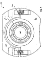
- the cleaning brush 4 In order to transport the dirt particles in the cleaning device 1 in the direction of the adjacent dirt outlet 6, the cleaning brush 4 has two sections 7, 8 and with oppositely rotating bristles, which in these subareas 7, 8 removed from the guide roller 2 dirt particles to each adjacent dirt outlet 6 move.
- Schmutzauslässen 6 is in FIG. 2 only to see a dirt outlet 6. Since the opposing portions 7, 8 of the cleaning brush 4 easily solve the dirt particles located on the guide roller 2 and can transport inside the cleaning device 1 to the adjacent dirt outlet 6, the cleaning device 1 is also characterized by a good cleaning effect.
- the two sub-areas 7, 8 of the bristle field of the cleaning brush 4 have an approximately equal longitudinal extent and adjacent to each other approximately in the middle of the bristle field.
- the shaft 9 of the cleaning brush 4 is supported at its two shaft end regions and additionally also in the course of its longitudinal extension preferably approximately centrally by means of a shaft bearing 10.
- the cleaning brush 4 is pressurized in the region of its shaft bearing 10 by means of at least one compression spring 20, which compression spring 20 presses the cleaning brush 4 against the guide roller 2 to be cleaned.
- Fig. 3 the cleaning device 1 is shown in the region of one of its shaft bearings 10.
- the cleaning brush 4 is movably mounted at their Bürstenend Schemeen and preferably also in the region of the bristle field between the cleaning brush portions 7, 8.
- the cleaning brush is held in a cleaning brush bearing 21, which by means of a pressing force is movable against the guide roller.
- at least one compression spring 20 is provided as a pressing force, which is supported on a bearing receptacle 23 and the cleaning brush bearing 21 pressurized.
- the cleaning device 1 has a housing 12, which is made of an extruded profile.
- the housing 12 has a cavity 13 which is shaped in its clear cross section with a small distance to the outer periphery of the cleaning brush 4.
- the cavity is open on the longitudinal side, wherein the bristles 5 of the cleaning brush 4 project ready for use from the longitudinal cavity opening 14 of the extruded profile 12.
- FIG. 2 It is indicated that the cleaning brush 4 and the guide roller 2 to be cleaned by it have a common rotary drive 15.
- This rotary drive 15 is preferably designed so that the guide roller 2 on the one hand and the cleaning roller 4 on the other hand have opposite directions of rotation.
- Fig. 4 is the common rotary drive 15 shown in more detail, which is associated with the guide roller 2 on the one hand and the cleaning roller 4 on the other.
- This rotary drive 15 has a drive motor 25, whose drive shaft is connected to the cleaning roller 4 via a belt drive indicated by the drive wheels 26, 27.
- This belt drive is associated with a belt tensioner 28, which ensures despite the movable mounting of the cleaning brush 4 for a tensioned drive belt.
- the opposite direction of rotation of the guide roller 2 is achieved via two gears 29, 30, which are connected via a further, indicated by the drive wheels 31, 32 belt drive with a friction wheel 33 in drive connection.
- This friction wheel 33 acts on the roller surface of the guide roller 2 not shown here Fig. 4 is indicated that the cleaning device 1 can be applied by means of at least one pneumatic cylinder 34 to the guide roller 2 or brought from this distance.
- Fig. 1 is indicated that the housing 12 of the cleaning device 1 may have a preferably over the cleaning brush 4 extending detergent spray tube 35, the one Spray application to the cleaning brush 4 allowed.
- a detergent outlet 36 is provided, in which the detergent used can be collected again and removed from the housing 12.
- the cleaning device 1 shown here is characterized by its small footprint and by its high cleaning effect.
Landscapes
- Inking, Control Or Cleaning Of Printing Machines (AREA)
- Cleaning In General (AREA)
Claims (13)
- Dispositif de nettoyage (1) pour nettoyer au moins un rouleau de guidage (2) guidant une bande de papier (3) dans une presse rotative, lequel dispositif de nettoyage (1) présente au moins une brosse de nettoyage (4) pouvant être agencée dans la zone du rouleau de guidage (2) à nettoyer, de manière coaxiale à celui-ci dans l'espace libre délimité par la bande de papier (3), la brosse de nettoyage (4) présentant un champ de poils avec des poils (5) tournant de manière hélicoïdale et étant conçue au moins pendant la procédure de nettoyage de manière à pouvoir solliciter au moins partiellement le rouleau de guidage (2) avec son champ de poils de manière nettoyante, le dispositif de nettoyage (1) ayant au moins une décharge de saleté (6), par laquelle les particules de saleté pouvant être éliminées du rouleau de guidage (2) au moyen de la au moins une brosse de nettoyage (4) peuvent être évacuées, dans lequel le champ de poils de la au moins une brosse de nettoyage (4) a au moins deux zones partielles (7, 8) adjacentes avec des poils tournant en sens inverse, au moyen desquelles les particules de saleté éliminées du rouleau de guidage (2) dans ces zones partielles (7, 8) se déplacent soit vers une décharge de saleté commune agencée entre les zones partielles (7, 8) adjacentes de la brosse de nettoyage, soit vers une décharge de saleté (6) prévue respectivement sur le côté des zones d'extrémités frontales des zones partielles (7, 8) adjacentes de la brosse de nettoyage, caractérisé en ce que la brosse de nettoyage (4) a un entraînement rotatif (15), l'entraînement rotatif (15) avec le rouleau de guidage (2) pouvant être amené en connexion d'entraînement avec le rouleau de guidage par le biais d'au moins une roue de friction (33), la surface de rouleau du rouleau de guidage (2) pouvant être sollicitée par la roue de friction (33).
- Dispositif de nettoyage selon la revendication 1, caractérisé en ce que les deux zones partielles (7, 8) du champ de poils de la au moins une brosse de nettoyage (4) présentent une étendue longitudinale de même grandeur et sont adjacentes l'une à l'autre au milieu du champ de poils.
- Dispositif de nettoyage selon la revendication 1 ou 2, caractérisé en ce que la brosse de nettoyage (4) est logée de manière mobile transversalement à l'étendue longitudinale du rouleau de guidage et sollicite le rouleau de guidage (2) par pression au moyen d'une force de pression.
- Dispositif de nettoyage selon l'une des revendications 1 à 3, caractérisé en ce que la brosse de nettoyage (4) est logée de manière mobile au niveau de ses zones d'extrémités de brosse et/ou dans la zone du champ de poils de préférence entre les zones partielles (7, 8) de la brosse de nettoyage et/ou est sollicitée par pression par une force de pression.
- Dispositif de nettoyage selon l'une des revendications 1 à 4, caractérisé en ce qu'au moins un ressort de compression (20), qui sollicite par pression au moins un roulement de brosse de nettoyage (21), est prévu comme force de pression.
- Dispositif de nettoyage selon l'une des revendications 1 à 5, caractérisé en ce que la brosse de nettoyage (4) peut être entraînée en rotation dans le sens contraire comparé au rouleau de guidage (2) qui lui est attribué.
- Dispositif de nettoyage selon l'une des revendications 1 à 6, caractérisé en ce que le dispositif de nettoyage (1) présente un boîtier (12) qui est fabriqué à partir d'un profilé filé et/ou d'un profilé en métal ou en matière plastique.
- Dispositif de nettoyage selon l'une des revendications 1 à 7, caractérisé en ce que le boîtier (12) du dispositif de nettoyage (1) présente un espace creux (13) ouvert sur le côté longitudinal dans lequel la brosse de nettoyage (4) est logée de manière rotative.
- Dispositif de nettoyage selon l'une des revendications 1 à 8, caractérisé en ce que l'espace creux (13) est adapté dans sa périphérie interne à la forme de la périphérie externe de la brosse de nettoyage (4) avec un faible écartement.
- Dispositif de nettoyage selon l'une des revendications 1 à 9, dans lequel l'entraînement rotatif (15) se trouve en connexion d'entraînement avec le rouleau de guidage de telle sorte que le rouleau de guidage peut être déplacé même lorsque la presse rotative est en arrêt avec ou sans bande de papier guidée par le rouleau de guidage.
- Dispositif de nettoyage selon l'une des revendications 1 à 10, dans lequel l'entraînement rotatif (15) présente un moteur d'entraînement (25) dont l'arbre d'entraînement est raccordé au rouleau de nettoyage (4) par un entraînement par courroie.
- Dispositif de nettoyage selon la revendication 11, dans lequel est attribué à l'entraînement par courroie un tendeur de courroie (28) qui a pour fonction que la courroie d'entraînement soit toujours tendue malgré le logement mobile de la brosse de nettoyage (4).
- Dispositif de nettoyage selon la revendication 12, dans lequel la direction de rotation contraire du rouleau de guidage (2) est obtenue par deux roues d'engrenage (29, 30) qui se trouvent en connexion d'entraînement avec la roue de friction (33) par un autre entraînement par courroie indiqué par les roues d'entraînement (31, 32).
Applications Claiming Priority (1)
| Application Number | Priority Date | Filing Date | Title |
|---|---|---|---|
| DE102006046071A DE102006046071B3 (de) | 2006-09-27 | 2006-09-27 | Reinigungsvorrichtung für eine Rotationsdruckmaschine |
Publications (3)
| Publication Number | Publication Date |
|---|---|
| EP1908591A2 EP1908591A2 (fr) | 2008-04-09 |
| EP1908591A3 EP1908591A3 (fr) | 2008-04-16 |
| EP1908591B1 true EP1908591B1 (fr) | 2010-08-18 |
Family
ID=38830951
Family Applications (1)
| Application Number | Title | Priority Date | Filing Date |
|---|---|---|---|
| EP07018962A Not-in-force EP1908591B1 (fr) | 2006-09-27 | 2007-09-26 | Dispositif de nettoyage pour une presse rotative |
Country Status (3)
| Country | Link |
|---|---|
| US (1) | US20080087182A1 (fr) |
| EP (1) | EP1908591B1 (fr) |
| DE (2) | DE102006046071B3 (fr) |
Families Citing this family (3)
| Publication number | Priority date | Publication date | Assignee | Title |
|---|---|---|---|---|
| DE102009058744B4 (de) * | 2009-12-17 | 2012-11-29 | Technotrans Ag | Reinigungsvorrichtung für Druck- und Druckplattenzylinder |
| DE102014113178A1 (de) * | 2014-09-12 | 2016-03-17 | Manroland Web Systems Gmbh | Reinigungsvorrichtung für eine Druckmaschine |
| CN116899938A (zh) * | 2023-06-14 | 2023-10-20 | 安徽国风新材料股份有限公司 | 一种薄膜加工的胶辊辊面清洁装置 |
Family Cites Families (11)
| Publication number | Priority date | Publication date | Assignee | Title |
|---|---|---|---|---|
| DE3120983A1 (de) * | 1980-05-28 | 1982-04-29 | Dai Nippon Insatsu K.K., Tokyo | Vorrichtung zum waschen des gummituchzylinders einer rotations-offsetpresse |
| US4875611A (en) * | 1987-12-10 | 1989-10-24 | Xerox Corporation | Roll media feed roll system |
| DE3812678C3 (de) * | 1988-04-16 | 1996-04-11 | Heidelberger Druckmasch Ag | Vorrichtung zum Reinigen von zylindrischen Mantelflächen in Rotationsdruckmaschinen |
| NO305738B1 (no) * | 1990-06-14 | 1999-07-19 | Baldwin Technology Corp | Trykkingsanordning omfattende roterende t°rr-b°rsteorgan |
| US5597413A (en) * | 1992-12-07 | 1997-01-28 | Xerox Corporation | Donor brush |
| JP2592694Y2 (ja) * | 1993-07-15 | 1999-03-24 | ニッカ株式会社 | 印刷機シリンダ洗浄装置 |
| DE19860854A1 (de) * | 1998-12-31 | 2000-07-06 | Koenig & Bauer Ag | Vorrichtung zum Reinigen einer Walze |
| DE10053322A1 (de) * | 2000-10-27 | 2002-05-08 | Roland Man Druckmasch | Waschvorrichtung für ein Farbwerk einer Druckmaschine |
| US20020157205A1 (en) * | 2001-04-27 | 2002-10-31 | Akira Hara | Cylinder cleaning brush unit |
| JP2005001243A (ja) * | 2003-06-12 | 2005-01-06 | Baldwin Japan Ltd | シリンダ洗浄用洗浄液供給装置およびシリンダ洗浄用ブラシユニットおよびシリンダ洗浄装置 |
| DE10344115A1 (de) * | 2003-09-24 | 2005-04-21 | Richard Munz | Reinigungsvorrichtung für Druckzylinder |
-
2006
- 2006-09-27 DE DE102006046071A patent/DE102006046071B3/de not_active Expired - Fee Related
-
2007
- 2007-09-21 US US11/859,183 patent/US20080087182A1/en not_active Abandoned
- 2007-09-26 EP EP07018962A patent/EP1908591B1/fr not_active Not-in-force
- 2007-09-26 DE DE502007004763T patent/DE502007004763D1/de active Active
Also Published As
| Publication number | Publication date |
|---|---|
| EP1908591A2 (fr) | 2008-04-09 |
| DE502007004763D1 (de) | 2010-09-30 |
| US20080087182A1 (en) | 2008-04-17 |
| DE102006046071B3 (de) | 2008-01-24 |
| EP1908591A3 (fr) | 2008-04-16 |
Similar Documents
| Publication | Publication Date | Title |
|---|---|---|
| EP0963927B1 (fr) | Procédé pour nettoyer des bandes transporteuses | |
| EP2872697B1 (fr) | Balayeuse | |
| DE19627973A1 (de) | Reinigungsvorrichtung | |
| EP0693378B1 (fr) | Appareil pour nettoyer des cylindres | |
| EP3140441B1 (fr) | Dispositif comprenant un banc d'étirage pour le nettoyage de surfaces de cylindres d'un dispositif d'étirage | |
| EP1908591B1 (fr) | Dispositif de nettoyage pour une presse rotative | |
| EP3310235B1 (fr) | Appareil de nettoyage pour une action sur une surface à nettoyer | |
| WO1996026317A1 (fr) | Dispositif de nettoyage | |
| DE60211410T2 (de) | Maschine zur Reinigung einer Plane | |
| DE1427953C3 (de) | Einrichtung zum Reinigen der Arbeitswalzen in einem Walzgerüst | |
| WO1999054538A2 (fr) | Machine pour le travail en surface d'au moins une bande de materiau textile, en particulier pour le lainage et/ou l'emerisage ou operation analogue | |
| DE2124085A1 (fr) | ||
| DE2458241A1 (de) | Verfahren und vorrichtung zum kardieren von vliesstoffen | |
| DE10115670C1 (de) | Vorrichtung zur Reinigung der Oberfläche(n) einer bewegten Materialbahn | |
| DE9208909U1 (de) | Vorrichtung zum Reinigen einer umlaufenden Gewebebahn in einer Papiermaschine | |
| EP1601533B1 (fr) | Dispositif de nettoyage pour cylindres d'impression | |
| EP2140066A1 (fr) | Dispositif de nettoyage | |
| DE19860855A1 (de) | Vorrichtung zum Reinigen einer Walze | |
| DE19860859A1 (de) | Vorrichtung zum Reinigen einer Walze | |
| DE4314728C2 (de) | Walzenpresse zum Extrudieren plastischer Massen | |
| WO2008095551A1 (fr) | Groupe d'impression d'une presse rotative et procédé de lavage d'un groupe de mouillage d'un groupe d'impression | |
| DE102021006373A1 (de) | Reinigungsvorrichtung für ein mit Beschichtungsmittel verunreinigtes Transportband | |
| DE19635217C2 (de) | Vorrichtung zum Entwässern einer Faserstoffsuspension | |
| DE102012018895A1 (de) | Reinigungsvorrichtung | |
| DE202014105776U1 (de) | Reinigungsvorrichtung zum bedarfsweisen Reinigen von Endlos-Transportbändern |
Legal Events
| Date | Code | Title | Description |
|---|---|---|---|
| PUAI | Public reference made under article 153(3) epc to a published international application that has entered the european phase |
Free format text: ORIGINAL CODE: 0009012 |
|
| PUAL | Search report despatched |
Free format text: ORIGINAL CODE: 0009013 |
|
| AK | Designated contracting states |
Kind code of ref document: A2 Designated state(s): AT BE BG CH CY CZ DE DK EE ES FI FR GB GR HU IE IS IT LI LT LU LV MC MT NL PL PT RO SE SI SK TR |
|
| AX | Request for extension of the european patent |
Extension state: AL BA HR MK RS |
|
| AK | Designated contracting states |
Kind code of ref document: A3 Designated state(s): AT BE BG CH CY CZ DE DK EE ES FI FR GB GR HU IE IS IT LI LT LU LV MC MT NL PL PT RO SE SI SK TR |
|
| AX | Request for extension of the european patent |
Extension state: AL BA HR MK RS |
|
| 17P | Request for examination filed |
Effective date: 20080515 |
|
| 17Q | First examination report despatched |
Effective date: 20080709 |
|
| AKX | Designation fees paid |
Designated state(s): DE FR GB IT SE |
|
| GRAP | Despatch of communication of intention to grant a patent |
Free format text: ORIGINAL CODE: EPIDOSNIGR1 |
|
| GRAS | Grant fee paid |
Free format text: ORIGINAL CODE: EPIDOSNIGR3 |
|
| GRAA | (expected) grant |
Free format text: ORIGINAL CODE: 0009210 |
|
| AK | Designated contracting states |
Kind code of ref document: B1 Designated state(s): DE FR GB IT SE |
|
| REG | Reference to a national code |
Ref country code: GB Ref legal event code: FG4D Free format text: NOT ENGLISH |
|
| REF | Corresponds to: |
Ref document number: 502007004763 Country of ref document: DE Date of ref document: 20100930 Kind code of ref document: P |
|
| REG | Reference to a national code |
Ref country code: SE Ref legal event code: TRGR |
|
| PGFP | Annual fee paid to national office [announced via postgrant information from national office to epo] |
Ref country code: DE Payment date: 20100928 Year of fee payment: 4 |
|
| PG25 | Lapsed in a contracting state [announced via postgrant information from national office to epo] |
Ref country code: IT Free format text: LAPSE BECAUSE OF FAILURE TO SUBMIT A TRANSLATION OF THE DESCRIPTION OR TO PAY THE FEE WITHIN THE PRESCRIBED TIME-LIMIT Effective date: 20100818 |
|
| PLBE | No opposition filed within time limit |
Free format text: ORIGINAL CODE: 0009261 |
|
| STAA | Information on the status of an ep patent application or granted ep patent |
Free format text: STATUS: NO OPPOSITION FILED WITHIN TIME LIMIT |
|
| 26N | No opposition filed |
Effective date: 20110519 |
|
| REG | Reference to a national code |
Ref country code: DE Ref legal event code: R097 Ref document number: 502007004763 Country of ref document: DE Effective date: 20110519 |
|
| PGFP | Annual fee paid to national office [announced via postgrant information from national office to epo] |
Ref country code: GB Payment date: 20110921 Year of fee payment: 5 Ref country code: SE Payment date: 20110920 Year of fee payment: 5 Ref country code: FR Payment date: 20110908 Year of fee payment: 5 |
|
| PG25 | Lapsed in a contracting state [announced via postgrant information from national office to epo] |
Ref country code: SE Free format text: LAPSE BECAUSE OF NON-PAYMENT OF DUE FEES Effective date: 20120927 |
|
| REG | Reference to a national code |
Ref country code: SE Ref legal event code: EUG |
|
| GBPC | Gb: european patent ceased through non-payment of renewal fee |
Effective date: 20120926 |
|
| REG | Reference to a national code |
Ref country code: FR Ref legal event code: ST Effective date: 20130531 |
|
| PG25 | Lapsed in a contracting state [announced via postgrant information from national office to epo] |
Ref country code: DE Free format text: LAPSE BECAUSE OF NON-PAYMENT OF DUE FEES Effective date: 20130403 Ref country code: GB Free format text: LAPSE BECAUSE OF NON-PAYMENT OF DUE FEES Effective date: 20120926 |
|
| PG25 | Lapsed in a contracting state [announced via postgrant information from national office to epo] |
Ref country code: FR Free format text: LAPSE BECAUSE OF NON-PAYMENT OF DUE FEES Effective date: 20121001 |
|
| REG | Reference to a national code |
Ref country code: DE Ref legal event code: R119 Ref document number: 502007004763 Country of ref document: DE Effective date: 20130403 |