EP1908418B1 - Anastomosenapplikator - Google Patents
Anastomosenapplikator Download PDFInfo
- Publication number
- EP1908418B1 EP1908418B1 EP06021055A EP06021055A EP1908418B1 EP 1908418 B1 EP1908418 B1 EP 1908418B1 EP 06021055 A EP06021055 A EP 06021055A EP 06021055 A EP06021055 A EP 06021055A EP 1908418 B1 EP1908418 B1 EP 1908418B1
- Authority
- EP
- European Patent Office
- Prior art keywords
- distal
- proximal
- anvil
- actuating
- surgical instrument
- Prior art date
- Legal status (The legal status is an assumption and is not a legal conclusion. Google has not performed a legal analysis and makes no representation as to the accuracy of the status listed.)
- Active
Links
- 230000006835 compression Effects 0.000 claims abstract description 89
- 238000007906 compression Methods 0.000 claims abstract description 89
- 230000014759 maintenance of location Effects 0.000 claims abstract description 28
- 238000005520 cutting process Methods 0.000 claims description 32
- 230000004044 response Effects 0.000 claims description 15
- 230000007246 mechanism Effects 0.000 claims description 12
- 230000000916 dilatatory effect Effects 0.000 claims description 9
- 238000003780 insertion Methods 0.000 claims description 9
- 230000037431 insertion Effects 0.000 claims description 9
- 241001417534 Lutjanidae Species 0.000 claims description 5
- 210000001519 tissue Anatomy 0.000 description 35
- 230000003872 anastomosis Effects 0.000 description 17
- 210000002784 stomach Anatomy 0.000 description 8
- 208000008589 Obesity Diseases 0.000 description 6
- 230000015572 biosynthetic process Effects 0.000 description 6
- 208000012696 congenital leptin deficiency Diseases 0.000 description 5
- 238000000034 method Methods 0.000 description 5
- 208000001022 morbid obesity Diseases 0.000 description 5
- 238000013459 approach Methods 0.000 description 4
- 239000012530 fluid Substances 0.000 description 4
- 230000002496 gastric effect Effects 0.000 description 4
- 230000008901 benefit Effects 0.000 description 3
- 235000013305 food Nutrition 0.000 description 3
- 238000002513 implantation Methods 0.000 description 3
- 239000000463 material Substances 0.000 description 3
- 210000000056 organ Anatomy 0.000 description 3
- 210000000813 small intestine Anatomy 0.000 description 3
- 238000001356 surgical procedure Methods 0.000 description 3
- 230000001419 dependent effect Effects 0.000 description 2
- 238000006073 displacement reaction Methods 0.000 description 2
- 230000037406 food intake Effects 0.000 description 2
- 235000012631 food intake Nutrition 0.000 description 2
- 230000002452 interceptive effect Effects 0.000 description 2
- 230000000968 intestinal effect Effects 0.000 description 2
- 230000004048 modification Effects 0.000 description 2
- 238000012986 modification Methods 0.000 description 2
- 208000019693 Lung disease Diseases 0.000 description 1
- 206010025476 Malabsorption Diseases 0.000 description 1
- 208000004155 Malabsorption Syndromes Diseases 0.000 description 1
- 235000013290 Sagittaria latifolia Nutrition 0.000 description 1
- 208000006011 Stroke Diseases 0.000 description 1
- 230000009471 action Effects 0.000 description 1
- 229920000249 biocompatible polymer Polymers 0.000 description 1
- 210000004204 blood vessel Anatomy 0.000 description 1
- 235000015246 common arrowhead Nutrition 0.000 description 1
- 238000009223 counseling Methods 0.000 description 1
- 230000008878 coupling Effects 0.000 description 1
- 238000010168 coupling process Methods 0.000 description 1
- 238000005859 coupling reaction Methods 0.000 description 1
- 230000007812 deficiency Effects 0.000 description 1
- 238000011161 development Methods 0.000 description 1
- 206010012601 diabetes mellitus Diseases 0.000 description 1
- 235000005911 diet Nutrition 0.000 description 1
- 230000000378 dietary effect Effects 0.000 description 1
- 230000000694 effects Effects 0.000 description 1
- 238000005401 electroluminescence Methods 0.000 description 1
- 208000019622 heart disease Diseases 0.000 description 1
- 238000002347 injection Methods 0.000 description 1
- 239000007924 injection Substances 0.000 description 1
- 230000007794 irritation Effects 0.000 description 1
- 238000005304 joining Methods 0.000 description 1
- 238000002357 laparoscopic surgery Methods 0.000 description 1
- 230000007774 longterm Effects 0.000 description 1
- 238000004519 manufacturing process Methods 0.000 description 1
- 229910052751 metal Inorganic materials 0.000 description 1
- 239000002184 metal Substances 0.000 description 1
- 150000002739 metals Chemical class 0.000 description 1
- 235000020824 obesity Nutrition 0.000 description 1
- 230000000144 pharmacologic effect Effects 0.000 description 1
- 230000036186 satiety Effects 0.000 description 1
- 235000019627 satiety Nutrition 0.000 description 1
- 239000000243 solution Substances 0.000 description 1
- 210000001562 sternum Anatomy 0.000 description 1
- 238000002560 therapeutic procedure Methods 0.000 description 1
- 238000013519 translation Methods 0.000 description 1
Images


Classifications
-
- A—HUMAN NECESSITIES
- A61—MEDICAL OR VETERINARY SCIENCE; HYGIENE
- A61B—DIAGNOSIS; SURGERY; IDENTIFICATION
- A61B17/00—Surgical instruments, devices or methods
- A61B17/11—Surgical instruments, devices or methods for performing anastomosis; Buttons for anastomosis
- A61B17/1114—Surgical instruments, devices or methods for performing anastomosis; Buttons for anastomosis of the digestive tract, e.g. bowels or oesophagus
-
- A—HUMAN NECESSITIES
- A61—MEDICAL OR VETERINARY SCIENCE; HYGIENE
- A61B—DIAGNOSIS; SURGERY; IDENTIFICATION
- A61B17/00—Surgical instruments, devices or methods
- A61B17/068—Surgical staplers, e.g. containing multiple staples or clamps
- A61B17/0682—Surgical staplers, e.g. containing multiple staples or clamps for applying U-shaped staples or clamps, e.g. without a forming anvil
- A61B17/0686—Surgical staplers, e.g. containing multiple staples or clamps for applying U-shaped staples or clamps, e.g. without a forming anvil having a forming anvil staying below the tissue during stapling
-
- A—HUMAN NECESSITIES
- A61—MEDICAL OR VETERINARY SCIENCE; HYGIENE
- A61B—DIAGNOSIS; SURGERY; IDENTIFICATION
- A61B17/00—Surgical instruments, devices or methods
- A61B17/11—Surgical instruments, devices or methods for performing anastomosis; Buttons for anastomosis
- A61B17/115—Staplers for performing anastomosis, e.g. in a single operation
-
- A—HUMAN NECESSITIES
- A61—MEDICAL OR VETERINARY SCIENCE; HYGIENE
- A61B—DIAGNOSIS; SURGERY; IDENTIFICATION
- A61B17/00—Surgical instruments, devices or methods
- A61B17/11—Surgical instruments, devices or methods for performing anastomosis; Buttons for anastomosis
- A61B2017/1135—End-to-side connections, e.g. T- or Y-connections
-
- A—HUMAN NECESSITIES
- A61—MEDICAL OR VETERINARY SCIENCE; HYGIENE
- A61B—DIAGNOSIS; SURGERY; IDENTIFICATION
- A61B17/00—Surgical instruments, devices or methods
- A61B17/11—Surgical instruments, devices or methods for performing anastomosis; Buttons for anastomosis
- A61B2017/1139—Side-to-side connections, e.g. shunt or X-connections
Definitions
- the present invention relates, in general, to devices for surgically modifying organs and vessels and more particularly to an applier for an anastomotic ring device for joining two organs or two parts of the same organ, such as the stomach and the small intestine and, within certain limits, blood vessels.
- morbid obesity The percentage of the world population suffering from morbid obesity is steadily increasing. Severely obese persons are susceptible to increased risk of heart disease, stroke, diabetes, pulmonary disease, and accidents. Because of the effect of morbid obesity to the life of a patient, methods for treating morbid obesity are being researched.
- Surgical methods of treating morbid obesity have been increasingly used with greater success. These approaches may be generalized as those that reduce the effective size of the stomach, limiting the amount of food intake, and those that create malabsorption of the food that has been eaten.
- AGB adjustable gastric bands
- a fluid conduit communicates between an inwardly presented fluid bladder of the AGB to a fluid injection port subcutaneously placed in front of the patients sternum.
- a syringe needle may then inject or withdraw fluid as desired to adjust the AGB.
- an anastomotic ring device requires additional operational steps in order for instance to approximate the tissues involved in the anastomosis, create the anastomotic passage by pearcing, tissue widening or incision, as well as the withdrawal and transportation out of the body of the surgical instruments or parts of the anastomotic applier.
- a prior art example of a surgical stapler is disclosed in WO 01/54594 A1 and an example of a known anastomic fastening ring is disclosed e.g. in EP 0 517 488 A1 .
- Document EP 0 517 488 A1 also discloses a surgical instrument for implanting this anastomotic fastening ring, which includes an anvil, an actuating member, a handle including an actuating mechanism and an elongate shaft connecting the handle with the actuating member for transmitting of tensile force for approximation of the ring parts.
- the aim of the present invention is therefore to provide a surgical instrument for implanting an anastomotic ring device in a laparoscopic or open surgery intervention having features which overcome the drawbacks cited with reference to the prior art.
- a particular aim of the present invention is to propose an anastomotic applier that incorporates a plurality of the above listed functions without increasing the complexity of the structure and handling of the applier itself.
- a further aim of the present invention is to provide an anastomotic applier which enables the surgeon to create an anastomosis requiring less dexterity for the correct reciprocal positioning of the instrument parts and of the body tissue to be connected.
- a surgical instrument for implanting an anastomotic ring device comprising:
- figure 1 depicts an applier 1 that advantageously laparoscopically, but also through a hand port or under open surgery conditions, or endoscopically if the dimension of the natural duct allows it, deploys and actuates an anastomotic ring device 2 having a distal compression ring 2A and a proximal compression ring 2B with a retention element or a separate retention element 2C suitable to snap connect the two compression rings 2A, 2B to another in order to form an anastomotic attachment between a distal tissue 3 (for instance intestinal wall tissue) and a proximal tissue 4 (for instance intestinal or gastric wall tissue) at an anastomosis target size, such as in a bariatric gastric bypass of a morbidly obese patient.
- a distal tissue 3 for instance intestinal wall tissue
- a proximal tissue 4 for instance intestinal or gastric wall tissue
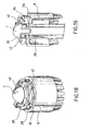
- the applier 1 comprises an elongate insertion shaft 5, a handle 6 proximally connected with an elongate shaft 5 and a detachable anvil 7 connectable with an actuating member 8 of the applier arranged at the distal end of the elongate shaft 5.
- the anvil 7 includes a first snap connecting part 9 for distally snap connect the anvil 7 in the anastomosis site with the actuating member 8 of the applier.
- the anvil 7 further defines a seat for receiving the distal compression ring 2A and holding it in position during the actuation of the anastomotic ring device 2.
- the seat may hold the distal compression ring 2A by press-fit, snap-fit, friction fit or shape fit.
- the anvil 7 includes a distal, preferably conical, head 10 connected to a central rod 11 extending proximally from the head 10 and supporting a retractable holder 12.
- the anvil head 10 has an outer diameter less than the inner diameter of a central passage aperture of the anastomotic ring device formed by corresponding passage apertures of both compression rings 2A, 2B and the retention element 2C.
- the retractable holder 12 includes a radially deflectable or displaceable elongate release portion 13 with sloping release surfaces 14 and opposite holding teeth 15 extending radially outward from a distal end of the elongate release portion 13.
- the holding teeth 15 bear against a proximal bearing surface of the anvil head 10 and their ends protrude radially over the anvil head's outer periphery and are configured to engage corresponding holding surfaces, for instance one ore more circumferential grooves 16, of the distal compression ring 2A.
- a radial flexural displacement of the elongate release portion 13 causes the holding teeth 15 to retract radially inwardly and disconnect from the distal compression ring 2A for enabling the anvil head 10 together with the retracted holder 12 to be withdrawn in proximal direction through the center opening of the anastomotic ring device 2.
- a proximal free end of the central rod 11 of the anvil forms a longitudinally slotted tubular seat with a substantially circumferential retaining edge forming the above mentioned first connecting part 9 suitable to snap receive a corresponding arrowhead shaped second connecting part 17 of the actuating member 8.
- the detachable anvil 7 comprises a tapered dilating portion 18 which extends proximally from the anvil head 10 and has a transverse dimension or diameter which increases in distal direction.
- the dilating portion 18 is preferably approximately cone-shaped and suitable to dilate the distal tissue 3 pierced by the anvil during approximation of the anvil towards the actuating member.
- the truncated cone of the dilating portion 18 is arranged radially outside the elongate release portion 13 and separated from the latter by a circumferential gap which allows the access of a releasing part 19 of the actuating member to the release portion.
- the cone shaped dilating portion 18 is arranged around the elongate release portion 13 and comprises two opposite longitudinal grooves receiving the sloping release surfaces 14 of the retractable holder and exposing them to the action of the corresponding releasing part 19 of the actuating member.
- a trocar 20 is directly formed on or connected with the proximal end of the first connecting part 9 of the anvil and suitable to pierce through the distal tissue 3 in order to create an initial hole for the subsequent formation of the anastomotic orifice.
- the elongate shaft 5 is preferably, but not necessarily rigid and substantially straight and includes an outer tube 21 having a distal end defining a seat 22 for receiving the proximal compression ring 2B and a proximal end connected with the handle 6.
- the seat 22 has a substantially circular shape with a size suitable to receive the proximal compression ring 2B with friction fit or snap fit in order to hold it in position during the insertion of the elongate shaft in the body of the patient and during the formation of the anastomosis.
- a substantially tubular actuating rod 23 is slidingly arranged inside the outer tube 21 and has a distal end defining a preferably annular pushing surface 24 which forms together with an internal cylindrical surface of the outer tube 21 a seat for slidingly receiving the retention element 2C which, in this embodiment, is separate from the proximal compression ring 2B.
- a proximal end of the actuating rod reaches inside the handle 6 and forms an annular flange 25.
- a compression spring element 26 is arranged between the flange 25 and a proximal end portion of the outer tube 21 or a spring seat especially formed in the handle, in order to elastically bias the tubular actuating rod 23 in proximal direction and maintain its proximal end in contact against a manual actuating trigger 27.
- the actuating trigger 27 is suitable for pushing the actuating rod 23 from a proximal rest position in distal direction for moving the retention element 2C towards and in snap engagement with the distal compression ring 2A to snap connect the compression rings 2A,
- the manual actuating trigger 27 includes a hinged trigger lever able to multiply the manually operated actuating force.
- the retention element 2C of the anastomotic ring device 2 comprises an annular proximal shoulder 28 suitable to engage a proximal surface of the proximal compression ring 2B and a longitudinal portion which distally protrudes from the proximal shoulder and forms elastically supported snapper teeth 29 extending radially outwardly from the longitudinal portion to enable snap engagement of the distal compression ring 2A.
- the longitudinal portion and the snapper teeth of the retention element 2C define slots or window openings 30 in alignment with the holding teeth 15 of the retractable holder 12 to enable the retention element 2C to be shifted in engagement with the distal compression ring 2A without interfering with the retractable holder 12.
- the elongate insertion shaft 5 further houses a central approximating rod 31 which is slidingly received inside the outer tube 21 and has a distal end defining the above mentioned second connecting part 17.
- the second connecting part 17 is preferably arrow head shaped and configured to snap-engage the first connecting part 9 of the detachable anvil for connecting the anvil with the actuating member 8.
- a proximal end of the central approximating rod 31 reaches inside the handle 6 where it is connected with a manual approximating knob 32 suitable for translating the approximating rod 31 from a distally advanced position in proximal direction to approximate the anvil carrying the distal compression ring towards the proximal compression ring.
- the approximating rod 31 is rotatably locked and the manual approximating knob 32 engages the its proximal end by means of a threaded connector 33 such that a rotation of the knob 32 causes the approximating rod 31 to translate along the threaded connector 33.
- a distal end of the second connecting part 17 has a trocar or a sharp tip formed or connected on it, suitable to pierce through the proximal tissue in order to create an initial hole for the subsequent formation of the anastomotic orifice.
- the elongate shaft 5 further houses a preferably substantially tubular releasing rod 34 which is slidably arranged inside the outer tube 21 and has a distal end defining the above mentioned releasing part 19 (e.g. a tubular push portion or two oppositely arranged push pins positioned such as to be in alignment with the opposite longitudinal grooves of the dilating portion 18 of the anvil) and suitable to contact with pressure the sloping release surfaces 14 of the anvil's retractable holder 12 to retract the holding teeth 15 from the distal compression ring 2A.
- a preferably substantially tubular releasing rod 34 which is slidably arranged inside the outer tube 21 and has a distal end defining the above mentioned releasing part 19 (e.g. a tubular push portion or two oppositely arranged push pins positioned such as to be in alignment with the opposite longitudinal grooves of the dilating portion 18 of the anvil) and suitable to contact with pressure the sloping release surfaces 14 of the anvil's retractable holder 12 to retract the
- a proximal end of the releasing rod 34 extends inside the handle 6 and is there connected with a manual releasing slider 35 suitable for pushing the releasing rod 34 from a proximal rest position in distal direction in order to retract the retractable holder.
- the manual release slider 35 includes a longitudinally adjustable sliding button directly connected with the proximal end of the release rod 34.
- the central approximating rod 31 is slidingly arranged inside the tubular release rod 34 in order that the tensioned approximating rod guides the release rod 34 (which transmits a compression force) and increases its lateral stability.
- the distal and proximal tissue to be attached in anastomosis is held between the two compression rings 2A, 2B by the compressive force operated through their snap engagement.
- the surfaces of the compression rings in contact with the tissue have preferably an enhanced roughness for increasing the friction between the anastomotic ring device and the tissue.
- the actuating member 8 of the anastomotic applier includes a needle applier configured to hold a group of needles or staples for piercing and fixating the tissue held between the distal and proximal compression ring.
- the needle applier is movable from a proximal rest position in distal direction, in response to a compressive needle force, for pushing the group of needles or staples into the anastomotic ring device.
- Such a needle force can be operated by a separate actuating mechanism and transmitted to the group of needles or staples by a separate pushing part or, which is preferable, the anastomotic applier 1 and the group of needles or staples are configured such that the needles can be applied by the same operation that causes the snap engagement of the two compression rings.
- the retention element 2C of the anastomotic ring device itself defines a seat for receiving a group of needles 36 or staples such that, in response to a distal movement of the above mentioned actuating part, i.e. the pushing surface 24, the retention element 2C moves in snap engagement with the compression rings 2A, 2B and pushes contemporaneously the group of needles 36 or staples in the anastomotic ring device piercing the tissue 3, 4 held between the proximal and distal compression rings.
- the group of needles might advantageously comprise a self supporting needle ring which can be arranged on the annular shoulder 28 of the retention element 2C.
- the detachable anvil is initially separate from the actuating member of the anastomotic applier 1 and can be positioned, for instance by means of surgical graspers or guide-devices (by laparoscopy, open surgery or through an endoscopic route) on the side of the tissue to be subject to anastomosis.
- the actuating member 8 of the anastomotic applier is inserted in the body of the patient, e.g. through a trocar port leading to the proximal side of the proximal tissue to be subject to anastomosis.
- the anvil trocar 20 By pushing the anvil first connecting part against the distal tissue 3, the anvil trocar 20 will pierce the distal tissue defining an initial distal lumen for the anastomosis. Analogously, by pushing the sharp tip of the second connecting portion of the actuating member against the proximal tissue, a proximal initial lumen is created. The distal and proximal tissue can now be placed proximate to another and correctly aligned by moving the insertion shaft 5 towards the anvil 7 or vice versa and snap connect the two snap connecting parts 9, 17 to connect the anvil with the actuating member 8 of the applier ( fig. 8 ).
- the increasing diameter of the cone shaped dilating portion 18 dilates the distal and proximal tissue to a diameter approximately equal to the inner diameter of the compression rings ( fig. 10 ).
- the retention element might be provided with different coupling features, e.g. friction fit features, or screw on features.
- the needle ring 36 is pushed into both compression rings and pierces the rings of proximal and distal tissue clamped between them ( fig. 12 ).
- the holding teeth are retracted within a circumference smaller than the internal diameter of the anastomotic ring device, it is possible to withdraw the anvil, without detaching it from the applier, proximally through the anastomotic lumen.
- the anastomotic applier can now be removed from the anastomosis ( fig.16, 17 ) and taken out of the patient.
- Figures 18 and 19 depict an alternative embodiment of the present invention, according to which the actuating member includes a cutting edge 38 movable from a proximal rest position in distal direction, in response to a compressive cutting force, for cutting the proximal and distal tissue clamped between the proximal and distal compression rings to create the anastomotic orifice.
- the handle includes an actuating mechanism for producing said compressive cutting force and the elongate shaft includes means for transmitting said compressive cutting force to the cutting edge.
- the cutting edge might be operatively coupled with the actuating part 24 such that the cutting of the anastomotic lumen is performed contemporaneously with the snap engagement of the ring device or at least due to the same actuating force, obviating a separate cutting mechanism.
- the detachable anvil may comprise a cut washer 39 providing a cutting surface for the cutting edge 38 to press against in order to complete the cut.
- the cut washer 39 includes a holding part 40 projecting radially outward from the anvil and being configured to hold the distal compression ring 2A for connecting it to the anvil 7.
- the cutting edge 38 is configured to cut away said projecting holding part 40 for disconnecting the distal compression ring from the anvil and enabling the anvil to be withdrawn in proximal direction through the center opening of the anastomotic ring device.
- Figures 18 and 19 show also an anastomotic ring device which differs slightly from that shown in the previous figures.
- the retention element is integral with the proximal compression ring and the rings have a circumferentially wavy shape which consents the formation of anastomotic lumen having a larger diameter than the ring devices itself as the wavy shape of the tissues forming the anastomosis will flatten and circumferentially lengthen after removing of the bio-absorbable or bio-fragmentable compression rings.
- These features of the ring device itself can be readily applied also to the previously described embodiments.
- the respective seats for receiving the wavy compression rings are advantageously, but not necessarily, wavy, too.
- such a cutting edge 38 might be also formed on the distal end of the snapper portion 2C for cutting through residual tissue projecting in the anastomotic lumen after widening, which would otherwise hinder the insertion of the snapper portion.
- the elongate insertion shaft might be curved or flexible in order to allow access through a long lumen, such as a section of the small intestine.
- the rods housed inside the elongate shaft for transmitting the approximation, actuation, release and cutting movements might be flexible in order to allow the flexion of the whole insertion shaft.
- Preferred materials for the fabrication of the applier and its single components are biocompatible polymers and/or metals.
- Preferred materials for the anastomotic ring device are biocompatible and advantageously bio-fragmentable or bio-absorbable materials.
- the applier 1 might advantageously include illuminating means, comprising an illuminating power source and an electroluminescence device known in the art and therefore not shown in the figures.
Landscapes
- Health & Medical Sciences (AREA)
- Life Sciences & Earth Sciences (AREA)
- Surgery (AREA)
- Molecular Biology (AREA)
- General Health & Medical Sciences (AREA)
- Biomedical Technology (AREA)
- Heart & Thoracic Surgery (AREA)
- Medical Informatics (AREA)
- Nuclear Medicine, Radiotherapy & Molecular Imaging (AREA)
- Animal Behavior & Ethology (AREA)
- Engineering & Computer Science (AREA)
- Public Health (AREA)
- Veterinary Medicine (AREA)
- Physiology (AREA)
- Surgical Instruments (AREA)
- Medical Preparation Storing Or Oral Administration Devices (AREA)
- Investigating Or Analyzing Non-Biological Materials By The Use Of Chemical Means (AREA)
- Packages (AREA)
Claims (17)
- Chirurgisches Instrument (1) zum Implantieren einer Anastomoseringvorrichtung (2), umfassend:einen Amboss (7), der einen ersten Verbindungsteil (9) und einen Sitz (15) zum Aufnehmen eines distalen Kompressionsrings (2A) der Anastomoseringvorrichtung (2) enthält; undein Betätigungselement (8), umfassend:einen oder mehrere Sitze (22) zum Aufnehmen eines proximalen Kompressionsrings (2B) und eines Rückhalteelements (2C) der Anastomoseringvorrichtung (2); undeinen zweiten Verbindungsteil (17), der so ausgeführt ist, dass er mit dem ersten Verbindungsteil (9) in Eingriff gelangt, um den Amboss (7) mit dem Betätigungselement (8) zu verbinden, wobei der zweite Verbindungsteil (17) in Reaktion auf eine Zugkraft von einer distalen Position in proximaler Richtung beweglich ist, um den Amboss (7) dem Betätigungselement (8) anzunähern; undeinen Betätigungsteil (24), der so ausgeführt ist, dass er auf das Rückhalteelement (2C) der Anastomoseringvorrichtung (2) einwirkt, wobei der Betätigungsteil (24) in Reaktion auf eine Kompressionskraft von einer proximalen Ruheposition in einer distalen Richtung beweglich ist, um das Rückhalteelement (2C) in Richtung zu dem distalen Kompressionsring (2A) und in den Eingriff mit demselben zu bewegen, um die Kompressionsringe zu verbinden;einen Griff (6), der einen Betätigungsmechanismus (32, 33, 25, 26, 27) enthält, um die Annäherungszugkraft und die Betätigungskompressionskraft zu erzeugen; undeinen langgestreckten Schaft (5), der den Griff (6) mit dem Betätigungselement (8) verbindet, wobei der Schaft Mittel zum Übertragen der Annäherungszugkraft zu dem zweiten Verbindungsteil (17) und der Betätigungskompressionskraft zu dem Betätigungsteil (24) enthält.
- Chirurgisches Instrument (1) nach Anspruch 1, wobei der erste Verbindungsteil (9) und der zweite Verbindungsteil (17) geeignet sind, mittels Schnappverbindung miteinander verbunden zu werden.
- Chirurgisches Instrument nach Anspruch 1 oder 2, wobei der Amboss (7) einen zurückziehbaren Halter (12) umfasst, der so ausgeführt ist, dass er den distalen Kompressionsring (2A) hält, und einen Freigabeabschnitt (13) enthält, wobei ein Wechsel des Freigabeabschnitts (13) den zurückziehbaren Halter (12) veranlasst, sich radial nach innen zurückzuziehen und sich vom distalen Kompressionsring (2A) zu trennen, um zu ermöglichen, dass der Amboss (7) in proximaler Richtung durch die Zentralöffnungen der Anastomoseringvorrichtung (2) zurückgezogen wird,
wobei das Betätigungselement (8) einen Freigabeteil (19) umfasst, der so ausgeführt ist, dass er auf den Freigabeabschnitt (13) des zurückziehbaren Halters (12) einwirkt, wobei der Freigabeteil (19) in Reaktion auf eine Freigabekraft von einer Ruheposition zu einer Freigabeposition beweglich ist, um den Freigabeabschnitt (13) zu verschieben,
wobei der Griff einen Betätigungsmechanismus (35) zum Erzeugen der Freigabekraft enthält und der langgestreckte Schaft (5) Mittel zum Übertragen der Freigabekraft auf den Freigabeteil (19) enthält. - Chirurgisches Instrument (1) nach Anspruch 2, wobei der zurückziehbare Halter (12) einen radial verschiebbaren langgestreckten Freigabeabschnitt (13) mit schrägen Freigabeflächen (14) und Haltezähnen (15), die sich von einem distalen Ende des langgestreckten Freigabeabschnitts (13) radial nach außen erstrecken und so konfiguriert sind, dass sie mit entsprechenden Halteflächen (16) des distalen Kompressionsrings (2A) in Eingriff gelangen, enthält, und
wobei der Freigabeteil (19) in Reaktion auf eine Freigabekompressionskraft von einer proximalen Ruheposition in einer distalen Richtung beweglich ist, um gegen die schrägen Freigabeflächen (14) des langgestreckten Freigabeabschnitts zu drücken und den Freigabeabschnitt zu verschieben, um die Haltezähne vom distalen Kompressionsring zurückzuziehen. - Chirurgisches Instrument (1) nach irgendeinem der vorangehenden Ansprüche, wobei der Amboss (7) abnehmbar ist und einen abgeschrägten Erweiterungsabschnitt (18) umfasst, der einen Durchmesser aufweist, der distal zunimmt, wobei der Erweiterungsabschnitt (18) geeignet ist, vom Amboss durchstoßenes Gewebe zu erweitern.
- Chirurgisches Instrument (1) nach irgendeinem der vorangehenden Ansprüche, wobei das Betätigungselement (8) eine Schneidkante (38) enthält, die in Reaktion auf eine Schneidekompressionskraft von einer proximalen Ruheposition in distaler Richtung beweglich ist, um proximal und distal Gewebe zu schneiden, das zwischen dem proximalen und distalen Kompressionsringen (2A, 2B) komprimiert ist, um die Anastomoseöffnung zu schaffen,
wobei der Griff (6) einen Betätigungsmechanismus zum Erzeugen der Schneidekompressionskraft enthält und der langgestreckte Schaft (5) Mittel zum Übertragen der Schneidekompressionskraft auf die Schneidkante (38) enthält. - Chirurgisches Instrument (1) nach dem vorangehenden Anspruch, wobei der Amboss (7) eine Schneidscheibe (39) umfasst, die eine Schneidfläche für den Durchstoß der Schneidkante (38) bereitstellt, um den Schnitt zu vollenden.
- Chirurgisches Instrument (1) nach dem vorangehenden Anspruch, wobei die Schneidscheibe (39) einen Halteteil (40) enthält, der vom Amboss (7) radial nach außen hervorsteht und so ausgeführt ist, dass er den distalen Kompressionsring (2A) hält, um diesen mit dem Amboss zu verbinden, wobei die Schneidkante (38) so ausgeführt ist, dass sie den vorstehenden Halteteil (40) abschneidet, um den distalen Kompressionsring (2A) vom Amboss (7) zu trennen und dem Amboss zu ermöglichen, in proximaler Richtung durch die Zentralöffnungen der Anastomoseringvorrichtung zurückgezogen zu werden.
- Chirurgisches Instrument (1) nach irgendeinem der vorangehenden Ansprüche, wobei das Betätigungselement (8) einen Nadelapplikator (24) enthält, der so ausgeführt ist, dass er eine Gruppe von Nadeln (36) oder Heftklammern zum Durchstoßen und Fixieren des zwischen dem distalen und dem proximalen Kompressionsring gehaltenen Gewebes hält,
wobei der Nadelapplikator (24) in Reaktion auf eine Nadelungskompressionskraft von einer proximalen Ruheposition in distaler Richtung beweglich ist, um die Gruppe von Nadeln (36) oder Heftklammern in die Anastomoseringvorrichtung zu drücken,
wobei der Griff (6) einen Betätigungsmechanismus zum Erzeugen der Nadelungskompressionskraft enthält und der langgestreckte Schaft (5) Mittel zum Übertragen der Nadelungskompressionskraft auf den Nadelapplikator (24) enthält. - Chirurgisches Instrument (1) nach Anspruch 9, wobei das Rückhalteelement (2C) einen Sitz (28) zum Aufnehmen einer Gruppe von Nadeln (36) oder Heftklammern definiert, so dass in Reaktion auf eine distale Bewegung des Betätigungsteils (24) der Schnappabschnitt (2C) sich in einen Schnappeingriff mit den Kompressionsringen (2A, 2B) bewegt und gleichzeitig die Gruppe von Nadeln (36) oder Heftklammern in die Anastomoseringvorrichtung drückt, die das zwischen dem proximalen und dem distalen Kompressionsring gehaltene Gewebe durchstoßen.
- Chirurgisches Instrument (1) nach irgendeinem der vorangehenden Ansprüche, wobei der langgestreckte Schaft (5) enthält:ein Außenrohr (21), wobei ein distales Ende des Außenrohres einen Sitz (22) zum Aufnehmen des proximalen Kompressionsrings (2A) definiert und ein proximales Ende des Außenrohrs mit einem Griffgehäuse (6) verbunden ist, das den Betätigungsmechanismus des chirurgischen Instruments umhüllt,eine im Wesentlichen rohrförmige Betätigungsstange (23), die gleitend innerhalb des Außenrohres (21) angeordnet ist, wobei ein distales Ende der Betätigungsstange einen Sitz (24) für das Rückhalteelement (2C) der Anastomoseringvorrichtung (2) definiert und ein proximales Ende (25) der Betätigungsstange in das Griffgehäuse (6) reicht und in proximaler Richtung elastisch vorbelastet ist und an einem Betätigungsauslöser (27) anliegt, der geeignet ist, die Betätigungsstange (23) in distaler Richtung zu drücken,eine Annäherungsstange (31), die gleitend innerhalb des Außenrohres (21) aufgenommen ist, wo ein distales Ende der Annäherungsstange (31) den zweiten Verbindungsteil (17) definiert und ein proximales Ende der Annäherungsstange in das Griffgehäuse (6) reicht und mit einem Annäherungsknopf (32) verbunden ist, der geeignet ist, die Annäherungsstange (31) in proximaler Richtung zu verschieben.
- Chirurgisches Instrument (1) nach dem vorangehenden Anspruch, wobei der langgestreckte Schaft (5) eine im Wesentlichen rohrförmige Freigabestange (34) enthält, die gleitend innerhalb des Außenrohres (21) angeordnet ist, wobei ein distales Ende der Freigabestange den Freigabeteil (19) definiert und ein proximales Ende der Freigabestange in das Griffgehäuse (6) reicht und mit einem Freigabeschlitten (35) verbunden ist, der geeignet ist, die Freigabestange in distaler Richtung zu drücken, um den zurückziehbaren Halter (12) zurückzuziehen.
- Chirurgisches Instrument (1) nach irgendeinem der Ansprüche 11 bis 12, wobei der Betätigungsauslöser (27) einen schwenkbaren Auslösehebel enthält und der Annäherungsknopf (32) mit dem drehfesten proximalen Ende der Annäherungsstange (31) mittels eines Schraubverbinders in Eingriff gelangt, so dass eine Drehung des Knopfes (32) die Annäherungsstange veranlasst, sich längs des Schraubverbinders zu verschieben.
- Chirurgisches Instrument (1) nach einem der Ansprüche 12 oder 13, wobei der manuelle Freigabeschlitten (35) einen longitudinal einstellbaren Schlittenknopf enthält, der direkt mit dem proximalen Ende der Freigabestange (34) verbunden ist.
- Chirurgisches Instrument (1) nach irgendeinem der vorangehenden Ansprüche, wobei der erste Verbindungsteil (9) des Ambosses ein proximales Ende enthält, das einen daran ausgebildeten oder damit verbundenen Trokar aufweist, der geeignet ist, durch eine Gewebeschicht zu stoßen.
- Chirurgisches Instrument (1) nach irgendeinem der vorangehenden Ansprüche, wobei der zweite Verbindungsteil (17) ein distales Ende enthält, das einen Trokar oder eine scharfe Spitze enthält, der/die daran ausgebildet oder damit verbunden ist und geeignet ist, durch eine Gewebeschicht zu stoßen.
- Chirurgisches Instrument (1) nach irgendeinem der vorangehenden Ansprüche, wobei der langgestreckte Einführungsschaft einen flexiblen Abschnitt umfasst, um einen Zugang durch ein gekrümmtes Lumen zu erlauben, wobei die innerhalb des langgestreckten Schaftes aufgenommenen Stangen zum Übertragen der Annäherungs-, Betätigungs-, Freigabe- und Schneidbewegungen flexible Abschnitte umfassen, um das Biegen des Einführungsschafts zu erlauben.
Priority Applications (5)
| Application Number | Priority Date | Filing Date | Title |
|---|---|---|---|
| DE602006012054T DE602006012054D1 (de) | 2006-10-06 | 2006-10-06 | Anastomosenapplikator |
| AT06021055T ATE456328T1 (de) | 2006-10-06 | 2006-10-06 | Anastomosenapplikator |
| EP06021055A EP1908418B1 (de) | 2006-10-06 | 2006-10-06 | Anastomosenapplikator |
| CN2007800373043A CN101522112B (zh) | 2006-10-06 | 2007-07-16 | 吻合施放器 |
| PCT/EP2007/057300 WO2008040580A1 (en) | 2006-10-06 | 2007-07-16 | An anastomotic applier |
Applications Claiming Priority (1)
| Application Number | Priority Date | Filing Date | Title |
|---|---|---|---|
| EP06021055A EP1908418B1 (de) | 2006-10-06 | 2006-10-06 | Anastomosenapplikator |
Publications (2)
| Publication Number | Publication Date |
|---|---|
| EP1908418A1 EP1908418A1 (de) | 2008-04-09 |
| EP1908418B1 true EP1908418B1 (de) | 2010-01-27 |
Family
ID=37806195
Family Applications (1)
| Application Number | Title | Priority Date | Filing Date |
|---|---|---|---|
| EP06021055A Active EP1908418B1 (de) | 2006-10-06 | 2006-10-06 | Anastomosenapplikator |
Country Status (5)
| Country | Link |
|---|---|
| EP (1) | EP1908418B1 (de) |
| CN (1) | CN101522112B (de) |
| AT (1) | ATE456328T1 (de) |
| DE (1) | DE602006012054D1 (de) |
| WO (1) | WO2008040580A1 (de) |
Families Citing this family (54)
| Publication number | Priority date | Publication date | Assignee | Title |
|---|---|---|---|---|
| US8663220B2 (en) | 2009-07-15 | 2014-03-04 | Ethicon Endo-Surgery, Inc. | Ultrasonic surgical instruments |
| US20110118764A1 (en) | 2009-08-14 | 2011-05-19 | Beane Richard M | Method and apparatus for effecting a minimally invasive distal anastomosis for an aortic valve bypass |
| US11090104B2 (en) | 2009-10-09 | 2021-08-17 | Cilag Gmbh International | Surgical generator for ultrasonic and electrosurgical devices |
| US8469981B2 (en) | 2010-02-11 | 2013-06-25 | Ethicon Endo-Surgery, Inc. | Rotatable cutting implement arrangements for ultrasonic surgical instruments |
| US9439668B2 (en) | 2012-04-09 | 2016-09-13 | Ethicon Endo-Surgery, Llc | Switch arrangements for ultrasonic surgical instruments |
| US20140005705A1 (en) | 2012-06-29 | 2014-01-02 | Ethicon Endo-Surgery, Inc. | Surgical instruments with articulating shafts |
| US9393037B2 (en) | 2012-06-29 | 2016-07-19 | Ethicon Endo-Surgery, Llc | Surgical instruments with articulating shafts |
| US9351754B2 (en) | 2012-06-29 | 2016-05-31 | Ethicon Endo-Surgery, Llc | Ultrasonic surgical instruments with distally positioned jaw assemblies |
| US9408622B2 (en) | 2012-06-29 | 2016-08-09 | Ethicon Endo-Surgery, Llc | Surgical instruments with articulating shafts |
| TWI626922B (zh) * | 2012-09-20 | 2018-06-21 | 卡波諾凡股份有限公司 | 用於吻合裝置的固定工具 |
| US9095367B2 (en) | 2012-10-22 | 2015-08-04 | Ethicon Endo-Surgery, Inc. | Flexible harmonic waveguides/blades for surgical instruments |
| CN104632813A (zh) * | 2013-11-12 | 2015-05-20 | 张造伦 | 多角型连接孔结构 |
| US9737355B2 (en) | 2014-03-31 | 2017-08-22 | Ethicon Llc | Controlling impedance rise in electrosurgical medical devices |
| US9913680B2 (en) | 2014-04-15 | 2018-03-13 | Ethicon Llc | Software algorithms for electrosurgical instruments |
| US10765470B2 (en) | 2015-06-30 | 2020-09-08 | Ethicon Llc | Surgical system with user adaptable techniques employing simultaneous energy modalities based on tissue parameters |
| US10687884B2 (en) | 2015-09-30 | 2020-06-23 | Ethicon Llc | Circuits for supplying isolated direct current (DC) voltage to surgical instruments |
| US10595930B2 (en) | 2015-10-16 | 2020-03-24 | Ethicon Llc | Electrode wiping surgical device |
| BR112018010062B1 (pt) * | 2015-11-17 | 2022-11-16 | Surgical Stabilization Technologies Inc | Aparelho de suporte de trocarte |
| CN108463177B (zh) * | 2015-11-19 | 2022-07-08 | 峰点接入有限责任公司 | 经皮进入系统和方法 |
| US11129670B2 (en) | 2016-01-15 | 2021-09-28 | Cilag Gmbh International | Modular battery powered handheld surgical instrument with selective application of energy based on button displacement, intensity, or local tissue characterization |
| US11058448B2 (en) | 2016-01-15 | 2021-07-13 | Cilag Gmbh International | Modular battery powered handheld surgical instrument with multistage generator circuits |
| US11229471B2 (en) | 2016-01-15 | 2022-01-25 | Cilag Gmbh International | Modular battery powered handheld surgical instrument with selective application of energy based on tissue characterization |
| US12193698B2 (en) | 2016-01-15 | 2025-01-14 | Cilag Gmbh International | Method for self-diagnosing operation of a control switch in a surgical instrument system |
| US10456193B2 (en) | 2016-05-03 | 2019-10-29 | Ethicon Llc | Medical device with a bilateral jaw configuration for nerve stimulation |
| US10463374B2 (en) * | 2016-05-17 | 2019-11-05 | Covidien Lp | Adapter assembly for a flexible circular stapler |
| GB201611306D0 (en) | 2016-06-29 | 2016-08-10 | Norwegian Univ Of Science And Tech (Ntnu) | Surgical stapler and a method of stapling tissue |
| US10376305B2 (en) | 2016-08-05 | 2019-08-13 | Ethicon Llc | Methods and systems for advanced harmonic energy |
| US11266430B2 (en) | 2016-11-29 | 2022-03-08 | Cilag Gmbh International | End effector control and calibration |
| US11779387B2 (en) | 2019-12-30 | 2023-10-10 | Cilag Gmbh International | Clamp arm jaw to minimize tissue sticking and improve tissue control |
| US11937863B2 (en) | 2019-12-30 | 2024-03-26 | Cilag Gmbh International | Deflectable electrode with variable compression bias along the length of the deflectable electrode |
| US20210196361A1 (en) | 2019-12-30 | 2021-07-01 | Ethicon Llc | Electrosurgical instrument with monopolar and bipolar energy capabilities |
| US11911063B2 (en) | 2019-12-30 | 2024-02-27 | Cilag Gmbh International | Techniques for detecting ultrasonic blade to electrode contact and reducing power to ultrasonic blade |
| US11452525B2 (en) | 2019-12-30 | 2022-09-27 | Cilag Gmbh International | Surgical instrument comprising an adjustment system |
| US12262937B2 (en) | 2019-12-30 | 2025-04-01 | Cilag Gmbh International | User interface for surgical instrument with combination energy modality end-effector |
| US12076006B2 (en) | 2019-12-30 | 2024-09-03 | Cilag Gmbh International | Surgical instrument comprising an orientation detection system |
| US11986201B2 (en) | 2019-12-30 | 2024-05-21 | Cilag Gmbh International | Method for operating a surgical instrument |
| US11986234B2 (en) | 2019-12-30 | 2024-05-21 | Cilag Gmbh International | Surgical system communication pathways |
| US12082808B2 (en) | 2019-12-30 | 2024-09-10 | Cilag Gmbh International | Surgical instrument comprising a control system responsive to software configurations |
| US11944366B2 (en) | 2019-12-30 | 2024-04-02 | Cilag Gmbh International | Asymmetric segmented ultrasonic support pad for cooperative engagement with a movable RF electrode |
| US12349961B2 (en) | 2019-12-30 | 2025-07-08 | Cilag Gmbh International | Electrosurgical instrument with electrodes operable in bipolar and monopolar modes |
| US11723716B2 (en) | 2019-12-30 | 2023-08-15 | Cilag Gmbh International | Electrosurgical instrument with variable control mechanisms |
| US11660089B2 (en) | 2019-12-30 | 2023-05-30 | Cilag Gmbh International | Surgical instrument comprising a sensing system |
| US11707318B2 (en) | 2019-12-30 | 2023-07-25 | Cilag Gmbh International | Surgical instrument with jaw alignment features |
| US11779329B2 (en) | 2019-12-30 | 2023-10-10 | Cilag Gmbh International | Surgical instrument comprising a flex circuit including a sensor system |
| US12053224B2 (en) | 2019-12-30 | 2024-08-06 | Cilag Gmbh International | Variation in electrode parameters and deflectable electrode to modify energy density and tissue interaction |
| US12114912B2 (en) | 2019-12-30 | 2024-10-15 | Cilag Gmbh International | Non-biased deflectable electrode to minimize contact between ultrasonic blade and electrode |
| US12336747B2 (en) | 2019-12-30 | 2025-06-24 | Cilag Gmbh International | Method of operating a combination ultrasonic / bipolar RF surgical device with a combination energy modality end-effector |
| US12343063B2 (en) | 2019-12-30 | 2025-07-01 | Cilag Gmbh International | Multi-layer clamp arm pad for enhanced versatility and performance of a surgical device |
| US11950797B2 (en) | 2019-12-30 | 2024-04-09 | Cilag Gmbh International | Deflectable electrode with higher distal bias relative to proximal bias |
| US12023086B2 (en) | 2019-12-30 | 2024-07-02 | Cilag Gmbh International | Electrosurgical instrument for delivering blended energy modalities to tissue |
| US11696776B2 (en) | 2019-12-30 | 2023-07-11 | Cilag Gmbh International | Articulatable surgical instrument |
| US12064109B2 (en) | 2019-12-30 | 2024-08-20 | Cilag Gmbh International | Surgical instrument comprising a feedback control circuit |
| US11786291B2 (en) | 2019-12-30 | 2023-10-17 | Cilag Gmbh International | Deflectable support of RF energy electrode with respect to opposing ultrasonic blade |
| US11812957B2 (en) | 2019-12-30 | 2023-11-14 | Cilag Gmbh International | Surgical instrument comprising a signal interference resolution system |
Family Cites Families (5)
| Publication number | Priority date | Publication date | Assignee | Title |
|---|---|---|---|---|
| DE1177768B (de) * | 1960-12-09 | 1964-09-10 | Dr Reindert Brummelkamp | Chirurgische Vorrichtung fuer die Resektion und Verbindung von Darmteilen |
| GR1002290B (el) * | 1991-06-03 | 1996-05-02 | Ethicon Inc. | Απορροφησιμο αναστομωτικο μεσο συνδεσεως. |
| HU225908B1 (en) * | 2000-01-24 | 2007-12-28 | Ethicon Endo Surgery Europe | Surgical circular stapling head |
| US20040254590A1 (en) * | 2003-06-16 | 2004-12-16 | Hoffman Gary H. | Method and instrument for the performance of stapled anastamoses |
| US7527185B2 (en) * | 2006-07-12 | 2009-05-05 | Niti Surgical Solutions Ltd. | Compression anastomosis ring assembly and applicator for use therewith |
-
2006
- 2006-10-06 DE DE602006012054T patent/DE602006012054D1/de active Active
- 2006-10-06 AT AT06021055T patent/ATE456328T1/de not_active IP Right Cessation
- 2006-10-06 EP EP06021055A patent/EP1908418B1/de active Active
-
2007
- 2007-07-16 CN CN2007800373043A patent/CN101522112B/zh not_active Expired - Fee Related
- 2007-07-16 WO PCT/EP2007/057300 patent/WO2008040580A1/en not_active Ceased
Also Published As
| Publication number | Publication date |
|---|---|
| DE602006012054D1 (de) | 2010-03-18 |
| CN101522112A (zh) | 2009-09-02 |
| WO2008040580A1 (en) | 2008-04-10 |
| EP1908418A1 (de) | 2008-04-09 |
| ATE456328T1 (de) | 2010-02-15 |
| CN101522112B (zh) | 2012-01-11 |
Similar Documents
| Publication | Publication Date | Title |
|---|---|---|
| EP1908418B1 (de) | Anastomosenapplikator | |
| EP1908422B1 (de) | Verbesserungen betreffend einen Applikator zum Anbringen von Anastomosenringen | |
| EP1520530B1 (de) | Applikator und Anastomosenring | |
| JP4531514B2 (ja) | 内腔間吻合のための単一内腔配置用リング | |
| JP4658557B2 (ja) | 自己配置ファスナーのための単一内腔吻合用アプライヤー | |
| US8211142B2 (en) | Method for hybrid gastro-jejunostomy | |
| AU2004216631A1 (en) | Unfolding anastomosis ring device | |
| CN101522111B (zh) | 用于吻合装置的锁定装置 | |
| AU2007201158B2 (en) | Method for hybrid gastro-jejunostomy |
Legal Events
| Date | Code | Title | Description |
|---|---|---|---|
| PUAI | Public reference made under article 153(3) epc to a published international application that has entered the european phase |
Free format text: ORIGINAL CODE: 0009012 |
|
| AK | Designated contracting states |
Kind code of ref document: A1 Designated state(s): AT BE BG CH CY CZ DE DK EE ES FI FR GB GR HU IE IS IT LI LT LU LV MC NL PL PT RO SE SI SK TR |
|
| AX | Request for extension of the european patent |
Extension state: AL BA HR MK RS |
|
| 17P | Request for examination filed |
Effective date: 20080917 |
|
| 17Q | First examination report despatched |
Effective date: 20081013 |
|
| AKX | Designation fees paid |
Designated state(s): AT BE BG CH CY CZ DE DK EE ES FI FR GB GR HU IE IS IT LI LT LU LV MC NL PL PT RO SE SI SK TR |
|
| AXX | Extension fees paid |
Extension state: BA Payment date: 20080917 Extension state: RS Payment date: 20080917 Extension state: MK Payment date: 20080917 Extension state: AL Payment date: 20080917 Extension state: HR Payment date: 20080917 |
|
| GRAP | Despatch of communication of intention to grant a patent |
Free format text: ORIGINAL CODE: EPIDOSNIGR1 |
|
| GRAS | Grant fee paid |
Free format text: ORIGINAL CODE: EPIDOSNIGR3 |
|
| GRAA | (expected) grant |
Free format text: ORIGINAL CODE: 0009210 |
|
| AK | Designated contracting states |
Kind code of ref document: B1 Designated state(s): AT BE BG CH CY CZ DE DK EE ES FI FR GB GR HU IE IS IT LI LT LU LV MC NL PL PT RO SE SI SK TR |
|
| AX | Request for extension of the european patent |
Extension state: AL BA HR MK RS |
|
| REG | Reference to a national code |
Ref country code: GB Ref legal event code: FG4D |
|
| REG | Reference to a national code |
Ref country code: CH Ref legal event code: EP |
|
| REG | Reference to a national code |
Ref country code: IE Ref legal event code: FG4D |
|
| REF | Corresponds to: |
Ref document number: 602006012054 Country of ref document: DE Date of ref document: 20100318 Kind code of ref document: P |
|
| REG | Reference to a national code |
Ref country code: NL Ref legal event code: VDEP Effective date: 20100127 |
|
| LTIE | Lt: invalidation of european patent or patent extension |
Effective date: 20100127 |
|
| PG25 | Lapsed in a contracting state [announced via postgrant information from national office to epo] |
Ref country code: AT Free format text: LAPSE BECAUSE OF FAILURE TO SUBMIT A TRANSLATION OF THE DESCRIPTION OR TO PAY THE FEE WITHIN THE PRESCRIBED TIME-LIMIT Effective date: 20100127 |
|
| PG25 | Lapsed in a contracting state [announced via postgrant information from national office to epo] |
Ref country code: IS Free format text: LAPSE BECAUSE OF FAILURE TO SUBMIT A TRANSLATION OF THE DESCRIPTION OR TO PAY THE FEE WITHIN THE PRESCRIBED TIME-LIMIT Effective date: 20100527 Ref country code: ES Free format text: LAPSE BECAUSE OF FAILURE TO SUBMIT A TRANSLATION OF THE DESCRIPTION OR TO PAY THE FEE WITHIN THE PRESCRIBED TIME-LIMIT Effective date: 20100508 Ref country code: PT Free format text: LAPSE BECAUSE OF FAILURE TO SUBMIT A TRANSLATION OF THE DESCRIPTION OR TO PAY THE FEE WITHIN THE PRESCRIBED TIME-LIMIT Effective date: 20100527 Ref country code: LT Free format text: LAPSE BECAUSE OF FAILURE TO SUBMIT A TRANSLATION OF THE DESCRIPTION OR TO PAY THE FEE WITHIN THE PRESCRIBED TIME-LIMIT Effective date: 20100127 Ref country code: NL Free format text: LAPSE BECAUSE OF FAILURE TO SUBMIT A TRANSLATION OF THE DESCRIPTION OR TO PAY THE FEE WITHIN THE PRESCRIBED TIME-LIMIT Effective date: 20100127 |
|
| PG25 | Lapsed in a contracting state [announced via postgrant information from national office to epo] |
Ref country code: SI Free format text: LAPSE BECAUSE OF FAILURE TO SUBMIT A TRANSLATION OF THE DESCRIPTION OR TO PAY THE FEE WITHIN THE PRESCRIBED TIME-LIMIT Effective date: 20100127 Ref country code: LV Free format text: LAPSE BECAUSE OF FAILURE TO SUBMIT A TRANSLATION OF THE DESCRIPTION OR TO PAY THE FEE WITHIN THE PRESCRIBED TIME-LIMIT Effective date: 20100127 Ref country code: FI Free format text: LAPSE BECAUSE OF FAILURE TO SUBMIT A TRANSLATION OF THE DESCRIPTION OR TO PAY THE FEE WITHIN THE PRESCRIBED TIME-LIMIT Effective date: 20100127 Ref country code: PL Free format text: LAPSE BECAUSE OF FAILURE TO SUBMIT A TRANSLATION OF THE DESCRIPTION OR TO PAY THE FEE WITHIN THE PRESCRIBED TIME-LIMIT Effective date: 20100127 |
|
| PG25 | Lapsed in a contracting state [announced via postgrant information from national office to epo] |
Ref country code: GR Free format text: LAPSE BECAUSE OF FAILURE TO SUBMIT A TRANSLATION OF THE DESCRIPTION OR TO PAY THE FEE WITHIN THE PRESCRIBED TIME-LIMIT Effective date: 20100428 Ref country code: EE Free format text: LAPSE BECAUSE OF FAILURE TO SUBMIT A TRANSLATION OF THE DESCRIPTION OR TO PAY THE FEE WITHIN THE PRESCRIBED TIME-LIMIT Effective date: 20100127 Ref country code: SE Free format text: LAPSE BECAUSE OF FAILURE TO SUBMIT A TRANSLATION OF THE DESCRIPTION OR TO PAY THE FEE WITHIN THE PRESCRIBED TIME-LIMIT Effective date: 20100127 Ref country code: CY Free format text: LAPSE BECAUSE OF FAILURE TO SUBMIT A TRANSLATION OF THE DESCRIPTION OR TO PAY THE FEE WITHIN THE PRESCRIBED TIME-LIMIT Effective date: 20100127 Ref country code: BE Free format text: LAPSE BECAUSE OF FAILURE TO SUBMIT A TRANSLATION OF THE DESCRIPTION OR TO PAY THE FEE WITHIN THE PRESCRIBED TIME-LIMIT Effective date: 20100127 Ref country code: RO Free format text: LAPSE BECAUSE OF FAILURE TO SUBMIT A TRANSLATION OF THE DESCRIPTION OR TO PAY THE FEE WITHIN THE PRESCRIBED TIME-LIMIT Effective date: 20100127 |
|
| PGFP | Annual fee paid to national office [announced via postgrant information from national office to epo] |
Ref country code: MC Payment date: 20100929 Year of fee payment: 5 |
|
| PG25 | Lapsed in a contracting state [announced via postgrant information from national office to epo] |
Ref country code: CZ Free format text: LAPSE BECAUSE OF FAILURE TO SUBMIT A TRANSLATION OF THE DESCRIPTION OR TO PAY THE FEE WITHIN THE PRESCRIBED TIME-LIMIT Effective date: 20100127 Ref country code: SK Free format text: LAPSE BECAUSE OF FAILURE TO SUBMIT A TRANSLATION OF THE DESCRIPTION OR TO PAY THE FEE WITHIN THE PRESCRIBED TIME-LIMIT Effective date: 20100127 Ref country code: BG Free format text: LAPSE BECAUSE OF FAILURE TO SUBMIT A TRANSLATION OF THE DESCRIPTION OR TO PAY THE FEE WITHIN THE PRESCRIBED TIME-LIMIT Effective date: 20100427 |
|
| PLBE | No opposition filed within time limit |
Free format text: ORIGINAL CODE: 0009261 |
|
| STAA | Information on the status of an ep patent application or granted ep patent |
Free format text: STATUS: NO OPPOSITION FILED WITHIN TIME LIMIT |
|
| 26N | No opposition filed |
Effective date: 20101028 |
|
| PG25 | Lapsed in a contracting state [announced via postgrant information from national office to epo] |
Ref country code: DK Free format text: LAPSE BECAUSE OF FAILURE TO SUBMIT A TRANSLATION OF THE DESCRIPTION OR TO PAY THE FEE WITHIN THE PRESCRIBED TIME-LIMIT Effective date: 20100127 |
|
| PGFP | Annual fee paid to national office [announced via postgrant information from national office to epo] |
Ref country code: IE Payment date: 20101015 Year of fee payment: 5 Ref country code: NL Payment date: 20101009 Year of fee payment: 5 |
|
| PGFP | Annual fee paid to national office [announced via postgrant information from national office to epo] |
Ref country code: CH Payment date: 20101012 Year of fee payment: 5 Ref country code: LU Payment date: 20101111 Year of fee payment: 5 |
|
| PG25 | Lapsed in a contracting state [announced via postgrant information from national office to epo] |
Ref country code: MC Free format text: LAPSE BECAUSE OF NON-PAYMENT OF DUE FEES Effective date: 20111031 |
|
| REG | Reference to a national code |
Ref country code: CH Ref legal event code: PL |
|
| PG25 | Lapsed in a contracting state [announced via postgrant information from national office to epo] |
Ref country code: CH Free format text: LAPSE BECAUSE OF NON-PAYMENT OF DUE FEES Effective date: 20111031 Ref country code: LI Free format text: LAPSE BECAUSE OF NON-PAYMENT OF DUE FEES Effective date: 20111031 |
|
| REG | Reference to a national code |
Ref country code: IE Ref legal event code: MM4A |
|
| PG25 | Lapsed in a contracting state [announced via postgrant information from national office to epo] |
Ref country code: HU Free format text: LAPSE BECAUSE OF FAILURE TO SUBMIT A TRANSLATION OF THE DESCRIPTION OR TO PAY THE FEE WITHIN THE PRESCRIBED TIME-LIMIT Effective date: 20100728 |
|
| PG25 | Lapsed in a contracting state [announced via postgrant information from national office to epo] |
Ref country code: IE Free format text: LAPSE BECAUSE OF NON-PAYMENT OF DUE FEES Effective date: 20111006 Ref country code: TR Free format text: LAPSE BECAUSE OF FAILURE TO SUBMIT A TRANSLATION OF THE DESCRIPTION OR TO PAY THE FEE WITHIN THE PRESCRIBED TIME-LIMIT Effective date: 20100127 |
|
| PG25 | Lapsed in a contracting state [announced via postgrant information from national office to epo] |
Ref country code: LU Free format text: LAPSE BECAUSE OF NON-PAYMENT OF DUE FEES Effective date: 20111006 |
|
| REG | Reference to a national code |
Ref country code: FR Ref legal event code: PLFP Year of fee payment: 11 |
|
| REG | Reference to a national code |
Ref country code: FR Ref legal event code: PLFP Year of fee payment: 12 |
|
| REG | Reference to a national code |
Ref country code: FR Ref legal event code: PLFP Year of fee payment: 13 |
|
| PGFP | Annual fee paid to national office [announced via postgrant information from national office to epo] |
Ref country code: DE Payment date: 20180925 Year of fee payment: 13 |
|
| PGFP | Annual fee paid to national office [announced via postgrant information from national office to epo] |
Ref country code: FR Payment date: 20190913 Year of fee payment: 14 |
|
| PGFP | Annual fee paid to national office [announced via postgrant information from national office to epo] |
Ref country code: IT Payment date: 20191009 Year of fee payment: 14 |
|
| PGFP | Annual fee paid to national office [announced via postgrant information from national office to epo] |
Ref country code: GB Payment date: 20191003 Year of fee payment: 14 |
|
| REG | Reference to a national code |
Ref country code: DE Ref legal event code: R119 Ref document number: 602006012054 Country of ref document: DE |
|
| PG25 | Lapsed in a contracting state [announced via postgrant information from national office to epo] |
Ref country code: DE Free format text: LAPSE BECAUSE OF NON-PAYMENT OF DUE FEES Effective date: 20200501 |
|
| GBPC | Gb: european patent ceased through non-payment of renewal fee |
Effective date: 20201006 |
|
| PG25 | Lapsed in a contracting state [announced via postgrant information from national office to epo] |
Ref country code: FR Free format text: LAPSE BECAUSE OF NON-PAYMENT OF DUE FEES Effective date: 20201031 |
|
| PG25 | Lapsed in a contracting state [announced via postgrant information from national office to epo] |
Ref country code: GB Free format text: LAPSE BECAUSE OF NON-PAYMENT OF DUE FEES Effective date: 20201006 |
|
| PG25 | Lapsed in a contracting state [announced via postgrant information from national office to epo] |
Ref country code: IT Free format text: LAPSE BECAUSE OF NON-PAYMENT OF DUE FEES Effective date: 20201006 |