EP1908386A2 - Buse d'aspiration manuelle ajustable - Google Patents
Buse d'aspiration manuelle ajustable Download PDFInfo
- Publication number
- EP1908386A2 EP1908386A2 EP08100583A EP08100583A EP1908386A2 EP 1908386 A2 EP1908386 A2 EP 1908386A2 EP 08100583 A EP08100583 A EP 08100583A EP 08100583 A EP08100583 A EP 08100583A EP 1908386 A2 EP1908386 A2 EP 1908386A2
- Authority
- EP
- European Patent Office
- Prior art keywords
- nozzle
- suction
- sections
- bristles
- tubular
- Prior art date
- Legal status (The legal status is an assumption and is not a legal conclusion. Google has not performed a legal analysis and makes no representation as to the accuracy of the status listed.)
- Granted
Links
- 238000000034 method Methods 0.000 claims description 6
- 238000000926 separation method Methods 0.000 claims description 4
- 230000007704 transition Effects 0.000 claims description 4
- 238000006243 chemical reaction Methods 0.000 abstract 1
- 238000006073 displacement reaction Methods 0.000 description 6
- 238000004140 cleaning Methods 0.000 description 3
- 238000005516 engineering process Methods 0.000 description 2
- FGRBYDKOBBBPOI-UHFFFAOYSA-N 10,10-dioxo-2-[4-(N-phenylanilino)phenyl]thioxanthen-9-one Chemical compound O=C1c2ccccc2S(=O)(=O)c2ccc(cc12)-c1ccc(cc1)N(c1ccccc1)c1ccccc1 FGRBYDKOBBBPOI-UHFFFAOYSA-N 0.000 description 1
- 238000010276 construction Methods 0.000 description 1
- 239000000428 dust Substances 0.000 description 1
- 230000002349 favourable effect Effects 0.000 description 1
- 238000009472 formulation Methods 0.000 description 1
- 238000009413 insulation Methods 0.000 description 1
- 239000000203 mixture Substances 0.000 description 1
- 230000002093 peripheral effect Effects 0.000 description 1
- 238000003825 pressing Methods 0.000 description 1
Images


Classifications
-
- A—HUMAN NECESSITIES
- A47—FURNITURE; DOMESTIC ARTICLES OR APPLIANCES; COFFEE MILLS; SPICE MILLS; SUCTION CLEANERS IN GENERAL
- A47L—DOMESTIC WASHING OR CLEANING; SUCTION CLEANERS IN GENERAL
- A47L9/00—Details or accessories of suction cleaners, e.g. mechanical means for controlling the suction or for effecting pulsating action; Storing devices specially adapted to suction cleaners or parts thereof; Carrying-vehicles specially adapted for suction cleaners
- A47L9/02—Nozzles
- A47L9/06—Nozzles with fixed, e.g. adjustably fixed brushes or the like
- A47L9/0606—Nozzles with fixed, e.g. adjustably fixed brushes or the like rigidly anchored brushes, combs, lips or pads
- A47L9/0613—Nozzles with fixed, e.g. adjustably fixed brushes or the like rigidly anchored brushes, combs, lips or pads with means specially adapted for picking up threads, hair or the like, e.g. brushes, combs, lint pickers or bristles pads
-
- A—HUMAN NECESSITIES
- A47—FURNITURE; DOMESTIC ARTICLES OR APPLIANCES; COFFEE MILLS; SPICE MILLS; SUCTION CLEANERS IN GENERAL
- A47L—DOMESTIC WASHING OR CLEANING; SUCTION CLEANERS IN GENERAL
- A47L9/00—Details or accessories of suction cleaners, e.g. mechanical means for controlling the suction or for effecting pulsating action; Storing devices specially adapted to suction cleaners or parts thereof; Carrying-vehicles specially adapted for suction cleaners
- A47L9/02—Nozzles
- A47L9/06—Nozzles with fixed, e.g. adjustably fixed brushes or the like
- A47L9/0673—Nozzles with fixed, e.g. adjustably fixed brushes or the like with removable brushes, combs, lips or pads
Definitions
- the invention relates to a hand-held suction nozzle for connection to a vacuum cleaner, in particular electric vacuum cleaner, with a tube-like nozzle portion about to eye eyes.
- Suction nozzles of the type in question are known. These are used, for example, in the form of crevice nozzles for cleaning upholstery, for example. These suction nozzles are directly connected to the vacuum cleaner or with the interposition of a suction tube or suction hose. For suction processing of overground surfaces, such as padding surfaces or for dust cleaning of furniture or the like, the hand-held suction nozzle is exchangeable for a correspondingly shaped surface or suction nozzle.
- a technical problem of the invention is considered to improve a hand-held suction nozzle of the type in question in particular handling technology on.
- a suction nozzle basic position that is, from a Fugendüsenwolf out can be the bristles, the back of the tube-like surrounding the suction channel bristle carrier are fixed, move beyond the front edge of the nozzle to form a suction nozzle.
- the nozzle section surrounding the bristles and the suction channel is stationary in this case.
- the tubular nozzle portion has a longitudinal separation to form two relatively rotatable nozzle sections, for converting a tubular crevice nozzle in a surface nozzle.
- the user is given a suction nozzle to the hand, which offers both the properties of a crevice nozzle, for example, for suction cleaning of upholstery joints or the like, as well as the benefits of a surface nozzle for oversoil suction processing.
- the user is no longer forced to change the nozzle, which also requires the constant availability of the second nozzle. Rather, the user can easily convert the tube-like crevice nozzle by pivoting the formed semi-tubular nozzle sections automatically into a surface nozzle by the intended longitudinal separation of the tubular nozzle portion.
- the inventive design proves to be advantageous, since in this case a frequent change between crevice nozzle and surface nozzle is particularly required.
- the proposed hand-held suction nozzle is to be used in three configurations. So first as a conventional tubular crevice nozzle. Second, by pivoting the semi-tubular nozzle sections as a surface nozzle and in addition by advancing the stored bristles beyond the front edge of the nozzle as a suction nozzle. The latter configuration is preferably accessible from the configuration of the crevice nozzle.
- the pivoting nozzle sections can be opened up to a 180 ° -Spr Son Geb, to achieve a maximum achievable only by pivoting the semi-tubular nozzle sections suction surface.
- the semi-tubular nozzle sections in this case form a suction orifice extending approximately transversely to the suction nozzle in the usual way, wherein the peripheral edges of the pivotable nozzle sections facing each other in the crevice nozzle configuration and more preferably close to each other in the surface nozzle configuration in conjunction with the surface to be cleaned, form, for example, with the pad to be cleaned, the edge seal of the Saugmundes formed.
- the transition from the tubular nozzle portion to the pivotable nozzle portions is preferably formed by an elastic cover.
- the elastic cover may, for example, be a bellows-type plastic or rubber grommet.
- the various positions of the pivotable nozzle sections and / or the bristles are adjustable by a push handle which is guided on the tubular nozzle section. By means of this push handle, which is more preferably displaceable in the axial extension of the suction nozzle, in particular in the axial extension of the tubular nozzle portion, the desired configuration of the suction nozzle is manually adjustable.
- the method of the pivotable nozzle sections in their respective position and / or the method of the bristles can be carried out by an electric motor, for which purpose a pushbutton or switch is more preferably placed in the region of the already hand-guided suction nozzle section.
- the pivoting of the nozzle sections takes place by means of an electric motor acting on one or both nozzle sections.
- the displacement of the bristles approximately in the axial extension of the suction nozzle or of the suction channel can be effected by a separate electric motor. More preferably, it is provided that the pivotable nozzle sections are in extended bristles in a slight spread position. This spread is in this case about 5 ° to 90 °, preferably 15 ° to 45 °. It adjusts accordingly a suction mouth, which approximately corresponds to the crevice nozzle in the configuration, however, wherein the advanced bristles protrude beyond the front nozzle edge or on the suction mouth addition.
- the proposed suction nozzle may be formed strictly straight in the longitudinal direction.
- the suction nozzle in the longitudinal direction in particular in the non-variable, tubular nozzle portion, which is also taken at the same time usually also by the hand of the user to design arcuate.
- the pivotable nozzle sections can be further biased by a spring element in a preferred basic position, such as in the basic position crevice nozzle configuration.
- the basic position can also be the surface nozzle configuration. At least one further to be approached from the basic position configuration is formed according to preferred latching or latching.
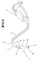
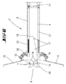
- FIG. 1 Shown and described is first with reference to FIG. 1 a hand-held suction nozzle 1, which is connected via a suction hose 2 to a running as a bottom unit vacuum cleaner 3 in terms of flow.
- connection of the suction nozzle 1 to the suction hose 2 is carried out in a conventional manner, for which purpose the suction nozzle 1 a non-illustrated, penetrated by the suction channel 4 plug-in section 5, which can be latched into the corresponding socket 6 of the suction hose 2.
- the suction nozzle 1 has a handle portion 7 and a subsequent tubular nozzle portion 8.
- the latter and the handle portion 7 are centrally penetrated by the suction channel 4, which terminates at the plug portion 5 facing away from the end of the nozzle portion 8 in a variable nozzle mouth 9.
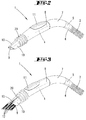
- the tubular nozzle portion 8 has in the region of its free end to a longitudinal separation, to form two equal, in a normal position according to FIG. 1
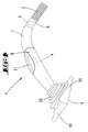
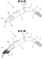
- the tube-like nozzle sections 10 are pivotable about a transversely directed to the longitudinal extent of the suction nozzle 1 axis x, so from the tube-like crevice nozzle configuration according to the representations in the FIGS. 1 . 2 and 5 in a 180 ° -sp Son ein for forming a surface nozzle according to the representations in the FIGS. 4 and 6 ,
- the remaining between the handle portion 7 and the pivotal nozzle portions 10 nozzle portion 8 is rigid and takes in the in the FIGS. 1 to 7 shown
- a push handle 11 by means of which the various configurations of the suction nozzle 1 can be selected.
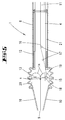
- FIGS. 5 to 7 show schematically the mechanics of the first embodiment for setting the desired nozzle configuration.
- the two pivotable nozzle sections 10 are mounted pivotably on pins 13 supported on the rigid nozzle section 8. These pins 13 each form pivot axes x.
- the spigots 13 comprehensive end portions of the nozzle sections 10 are formed in a circular segment.
- the mutually facing edge edges of the pivotable nozzle sections 10 are each provided with a sprocket portion 14. These comb each other.
- a radially projecting from the pivot axis x lever 15 is rotatably formed, on which in the illustrated embodiment, a tension element in the form of a pull cable 16 engages. This is the other end connected to the run on the tubular nozzle portion 8 push handle 11, this with the interposition of pulleys 17.
- a delta rope may be provided, which acts uniformly, simultaneously on both pivotable nozzle sections 10.
- Such solutions are known for example from the automotive field, so on in motor vehicle hand brakes. In such a solution, the sprocket portions 14 can be omitted.
- FIG. 5 illustrated basic position of the pivotable nozzle sections 10 is stop limited.
- the lever 15 is supported on a stop pin 18 connected to the tubular nozzle section 8.
- this basic position is spring-loaded, for which purpose a leg spring acting on the lever 15 in the direction of the stop pin 18 is provided.
- the transition from the tubular nozzle section 8 to the pivotable nozzle sections 10 is formed by an elastic cover 20 in the form of a bellows. As a result, the construction elements are covered. Next adjusting radial openings are sealed in the various positions of the pivotable nozzle sections 10, so that during operation no suction power negatively influencing secondary air can be sucked.
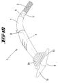
- both nozzle sections 10 are swung over the pull cable 16 and the tooth insulation until they reach a 180 ° spread position as shown in FIG. 6 ,
- This spreading position concerning the spreading nozzle configuration is stop-limited, so in the simplest way by striking the outer shells of the pivotal nozzle sections 10 against the corresponding marginal edges of the fixed, tubular nozzle section. 8
- the concentric with the suction channel 4 arranged bristles 12 are placed. These are rearward, that is mounted in the direction of the plug-in receptacle on a tubular support 21 in axial extension to this.
- This bristle carrier 21 is like the pull cable 16 connected to the push handle 11, so that a displacement of the push handle 11 at the same time brings a shift of the bristle carrier 21 and the bristles 12 with it.
- FIG. 7 shown suction brush configuration reachable.
- This by forward displacement of the push handle 11 in Direction to the free end of the suction nozzle 1, wherein first the bristles 12 are deflected radially inwardly by the nozzle mouth 9 toward pointed nozzle-shaped walls, after which the nach Wegende rigid bristle carrier 21, the pivotable nozzle sections 10 by internal wall urging to the outside, so that the bristles 12 can escape beyond the front nozzle edge.
- the nozzle sections 10 are supported with their inner walls circumferentially on the bristle carrier 21, this spring-loaded due to the restoring force of the tensioned leg spring 19.
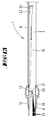
- FIGS. 8 to 13 show the suction nozzle 1 according to the invention in an alternative embodiment.
- the method of the pivotable nozzle sections 10 and the method of the bristles 12 follows electromotive.
- a switch 22 is provided in the region of the handle portion 7, via which the individual configurations can be selected.
- two electric motors 23 and 24 are provided for pivotal displacement of the nozzle sections 10 and the axial displacement of the bristles 12.
- the electric motor 23 is activated via the switch 22, via which a designated pull cable 16 is tightened.
- the latter acts similar to the embodiment described above via a lever 15 on the nozzle sections 10, for pivoting the same in a 180 ° -sp Dahl.
- the found surface nozzle position is fixed by latching the electric motor 23.
- the return to the crevice configuration is supported by a corresponding attacking leg spring 19.
- a slight swiveling of the nozzle sections 10 approximately into a 30 ° spread position is initially achieved via the electric motor 23, whereupon the bristles 12 together with the bristle carrier 21 are displaced in the axial direction of the suction nozzle 1 via the nozzle mouth 9 also by means of the electric motor 24.
- a spindle drive acting on the bristle carrier 21 via the electric motor 24 may be provided.
- the power supply of the electric motors 23 and 24 via a common device interface in the socket 6, according to the electric motors 23 and 24 are supplied via the vacuum cleaner 3.
- the inventive design a hand-held suction nozzle 1 is created, which can be changed quickly with simple manipulation in their configuration.
- no complicated replacement of several suction nozzles to be entrained is necessary.
- the one or the other desired configuration can be brought about quickly and safely by pressing a button or slide shift, this continues with conventional one-handed operation of the suction nozzle. 1
Landscapes
- Engineering & Computer Science (AREA)
- Mechanical Engineering (AREA)
- Nozzles For Electric Vacuum Cleaners (AREA)
- Electric Vacuum Cleaner (AREA)
- Treatment Of Fiber Materials (AREA)
- External Artificial Organs (AREA)
Applications Claiming Priority (2)
| Application Number | Priority Date | Filing Date | Title |
|---|---|---|---|
| DE102004055125A DE102004055125A1 (de) | 2004-11-16 | 2004-11-16 | Handgeführte Saugdüse |
| EP05810964A EP1814430B1 (fr) | 2004-11-16 | 2005-10-31 | Buse d'aspiration ajustable manuellement |
Related Parent Applications (2)
| Application Number | Title | Priority Date | Filing Date |
|---|---|---|---|
| EP05810964.6 Division | 2005-10-31 | ||
| EP05810964A Division EP1814430B1 (fr) | 2004-11-16 | 2005-10-31 | Buse d'aspiration ajustable manuellement |
Publications (3)
| Publication Number | Publication Date |
|---|---|
| EP1908386A2 true EP1908386A2 (fr) | 2008-04-09 |
| EP1908386A3 EP1908386A3 (fr) | 2010-01-20 |
| EP1908386B1 EP1908386B1 (fr) | 2012-11-28 |
Family
ID=35613826
Family Applications (2)
| Application Number | Title | Priority Date | Filing Date |
|---|---|---|---|
| EP05810964A Expired - Lifetime EP1814430B1 (fr) | 2004-11-16 | 2005-10-31 | Buse d'aspiration ajustable manuellement |
| EP08100583A Ceased EP1908386B1 (fr) | 2004-11-16 | 2005-10-31 | Buse d'aspiration manuelle ajustable |
Family Applications Before (1)
| Application Number | Title | Priority Date | Filing Date |
|---|---|---|---|
| EP05810964A Expired - Lifetime EP1814430B1 (fr) | 2004-11-16 | 2005-10-31 | Buse d'aspiration ajustable manuellement |
Country Status (6)
| Country | Link |
|---|---|
| EP (2) | EP1814430B1 (fr) |
| CN (2) | CN101060804B (fr) |
| AT (1) | ATE480174T1 (fr) |
| DE (2) | DE102004055125A1 (fr) |
| RU (2) | RU2007122491A (fr) |
| WO (1) | WO2006053823A2 (fr) |
Cited By (4)
| Publication number | Priority date | Publication date | Assignee | Title |
|---|---|---|---|---|
| EP3749159A4 (fr) * | 2018-02-09 | 2022-03-16 | SharkNinja Operating LLC | Accessoires pour appareil de traitement de surface |
| US11399675B2 (en) | 2018-07-31 | 2022-08-02 | Sharkninja Operating Llc | Upright surface treatment apparatus having removable pod |
| USD1067564S1 (en) | 2021-06-04 | 2025-03-18 | Sharkninja Operating Llc | Vacuum nozzle |
| USD1102692S1 (en) | 2021-06-04 | 2025-11-18 | Sharkninja Operating Llc | Vacuum cleaner |
Families Citing this family (9)
| Publication number | Priority date | Publication date | Assignee | Title |
|---|---|---|---|---|
| DE102008034458B4 (de) | 2008-07-24 | 2019-02-14 | Vorwerk & Co. Interholding Gmbh | Handgeführte Saugdüse zum Anschluss an einen Staubsauger und Saugdüse trennbar mit einem Düsenvorsatz |
| DE102008049715A1 (de) | 2008-09-30 | 2010-04-08 | Siemens Enterprise Communications Gmbh & Co. Kg | Verfahren und Anordnung zum Anbinden zumindest einer Mensch-Maschine-Schnittstelle zur Manipulation von zumindest einer im Rahmen von Videokonferenzen mit einem Videokonferenzsystem verbundenen Datenquelle |
| CN102485154B (zh) * | 2010-12-06 | 2016-07-06 | 南京乐金熊猫电器有限公司 | 屈伸式折角毛刷吸嘴 |
| US9700187B2 (en) | 2014-08-06 | 2017-07-11 | Emerson Electric Co. | Vacuum nozzle with integrated light |
| CN112353297A (zh) * | 2020-11-20 | 2021-02-12 | 虹汉科技(深圳)有限公司 | 一种吸嘴及吸尘器 |
| CL2020003104A1 (es) | 2020-11-27 | 2021-03-26 | Juan Claudio Droguett Larrain | Un dispositivo accesorio aspirador que provee una solución doméstica y no doméstica para aspirar y limpiar lugares de difícil acceso y objetos y lugares delicados que requieren de una acción más puntual y acotada sobre una pieza o lugar en particular. |
| US11607096B2 (en) * | 2021-02-03 | 2023-03-21 | Black & Decker, Inc. | Vacuum cleaner |
| US20250072695A1 (en) * | 2023-08-30 | 2025-03-06 | Bissell Inc. | Cleaning tool for a surface cleaner |
| CN120836962B (zh) * | 2025-09-22 | 2025-12-09 | 苏州爱之爱清洁电器科技有限公司 | 一种带灯扁吸结构 |
Citations (3)
| Publication number | Priority date | Publication date | Assignee | Title |
|---|---|---|---|---|
| FR1408028A (fr) | 1963-09-16 | 1965-08-06 | Electrolux Ab | Aspirateur à poussières |
| US5502870A (en) | 1993-12-16 | 1996-04-02 | Ragner; Gary D. | Five-function vacuum cleaner nozzle |
| FR2818115A1 (fr) | 2000-12-14 | 2002-06-21 | S N P 2 I | Buse d'aspiration comportant des poils de brosserie flexibles |
Family Cites Families (5)
| Publication number | Priority date | Publication date | Assignee | Title |
|---|---|---|---|---|
| NL127096C (fr) * | 1963-09-16 | |||
| US3780398A (en) * | 1972-02-08 | 1973-12-25 | J Candor | Flexible skirt construction for a vacuum cleaning nozzle and the like |
| JPH10262875A (ja) * | 1997-03-21 | 1998-10-06 | Kyoko Komatsu | 電気掃除機用細口兼用平型吸引口 |
| JPH11113815A (ja) * | 1997-10-20 | 1999-04-27 | Fumito Katono | 変化式吸い込み口 |
| CN1463659A (zh) * | 2002-06-12 | 2003-12-31 | 乐金电子(天津)电器有限公司 | 真空吸尘器的辅助吸头 |
-
2004
- 2004-11-16 DE DE102004055125A patent/DE102004055125A1/de not_active Withdrawn
-
2005
- 2005-10-31 EP EP05810964A patent/EP1814430B1/fr not_active Expired - Lifetime
- 2005-10-31 EP EP08100583A patent/EP1908386B1/fr not_active Ceased
- 2005-10-31 RU RU2007122491/12A patent/RU2007122491A/ru unknown
- 2005-10-31 CN CN2005800390196A patent/CN101060804B/zh not_active Expired - Fee Related
- 2005-10-31 CN CN2008100886411A patent/CN101273862B/zh not_active Expired - Fee Related
- 2005-10-31 AT AT05810964T patent/ATE480174T1/de not_active IP Right Cessation
- 2005-10-31 WO PCT/EP2005/055650 patent/WO2006053823A2/fr not_active Ceased
- 2005-10-31 DE DE502005010244T patent/DE502005010244D1/de not_active Expired - Lifetime
-
2008
- 2008-03-06 RU RU2008108842/12A patent/RU2008108842A/ru not_active Application Discontinuation
Patent Citations (3)
| Publication number | Priority date | Publication date | Assignee | Title |
|---|---|---|---|---|
| FR1408028A (fr) | 1963-09-16 | 1965-08-06 | Electrolux Ab | Aspirateur à poussières |
| US5502870A (en) | 1993-12-16 | 1996-04-02 | Ragner; Gary D. | Five-function vacuum cleaner nozzle |
| FR2818115A1 (fr) | 2000-12-14 | 2002-06-21 | S N P 2 I | Buse d'aspiration comportant des poils de brosserie flexibles |
Cited By (7)
| Publication number | Priority date | Publication date | Assignee | Title |
|---|---|---|---|---|
| EP3749159A4 (fr) * | 2018-02-09 | 2022-03-16 | SharkNinja Operating LLC | Accessoires pour appareil de traitement de surface |
| US11617482B2 (en) | 2018-02-09 | 2023-04-04 | Sharkninja Operating Llc | Accessories for a surface treatment apparatus having a plurality of operational states and surface treatment apparatus configured to actuate the same |
| US11399675B2 (en) | 2018-07-31 | 2022-08-02 | Sharkninja Operating Llc | Upright surface treatment apparatus having removable pod |
| US11998157B2 (en) | 2018-07-31 | 2024-06-04 | Sharkninja Operating Llc | Upright surface treatment apparatus having removable pod |
| US12433458B2 (en) | 2018-07-31 | 2025-10-07 | Sharkninja Operating Llc | Upright surface treatment apparatus having removable pod |
| USD1067564S1 (en) | 2021-06-04 | 2025-03-18 | Sharkninja Operating Llc | Vacuum nozzle |
| USD1102692S1 (en) | 2021-06-04 | 2025-11-18 | Sharkninja Operating Llc | Vacuum cleaner |
Also Published As
| Publication number | Publication date |
|---|---|
| RU2007122491A (ru) | 2008-12-27 |
| CN101060804B (zh) | 2010-04-14 |
| EP1908386A3 (fr) | 2010-01-20 |
| WO2006053823A3 (fr) | 2006-11-02 |
| CN101060804A (zh) | 2007-10-24 |
| CN101273862A (zh) | 2008-10-01 |
| RU2008108842A (ru) | 2009-09-20 |
| EP1814430B1 (fr) | 2010-09-08 |
| WO2006053823A2 (fr) | 2006-05-26 |
| DE502005010244D1 (de) | 2010-10-21 |
| CN101273862B (zh) | 2012-09-05 |
| EP1814430A2 (fr) | 2007-08-08 |
| ATE480174T1 (de) | 2010-09-15 |
| EP1908386B1 (fr) | 2012-11-28 |
| DE102004055125A1 (de) | 2006-05-18 |
Similar Documents
| Publication | Publication Date | Title |
|---|---|---|
| EP1908386B1 (fr) | Buse d'aspiration manuelle ajustable | |
| DE60100401T2 (de) | Schlauch- und rohranordnung | |
| DE68927501T3 (de) | Saugdüse | |
| DE3855221T2 (de) | Rotierende zahnbürtse mit doppelbürste | |
| DE60112258T2 (de) | Schlauch und rohr anordnung | |
| EP1386573B1 (fr) | Appareil de nettoyage avec un entraînement électrique | |
| DE102016014210A1 (de) | Staubsammelvorrichtung für ein elektrisch betriebenes werkzeug und elektrisch betriebenes werkzeug | |
| EP0834248A2 (fr) | Taille-haie motorisé | |
| DE68905252T2 (de) | Mundstueck fuer staubsauger. | |
| DE102018116547A1 (de) | Saugdüse für einen Staubsauger zum Reinigen eines Teppichs und Staubsauger mit einer derartigen Saugdüse | |
| EP2587977A1 (fr) | Buse d'aspirateur | |
| DE4238245C3 (de) | Staubabsaugeinrichtung für ein als Handgerät ausgebildetes, motorisch angetriebenes Gerät | |
| DE19500107A1 (de) | Zahnbürste | |
| DE9214059U1 (de) | Chirurgisches Instrument | |
| EP1924185A1 (fr) | Buse de sol pour aspirateur comprenant une barre a poils pouvant etre commandee | |
| DE2160833C3 (de) | Steckvorrichtung an einem Handgerät zur Körperpflege, insbesondere Zahn- und Mundpflege | |
| EP2100534A1 (fr) | Dispositif de lavage et de massage | |
| DE102005053392B3 (de) | Handgehaltenes elektrisch betriebenes Küchengerät mit einstellbarer Bedienelementposition | |
| DE19844810A1 (de) | Saugleitung für ein Saugreinigungsgerät | |
| DE102025121440A1 (de) | Handgeführtes Elektrogerät | |
| EP3298944B1 (fr) | Buse de sol pour aspirateur et aspirateur | |
| CH697578B1 (de) | Haarbürste. | |
| DE102020127225A1 (de) | Flächenbearbeitungsgerät mit einem schwenkbaren Handgriff | |
| DE9407606U1 (de) | Bodenpflegegerät | |
| DE20020762U1 (de) | Zahnbürste mit einem Bürstenteil zur interdentalen Reinigung |
Legal Events
| Date | Code | Title | Description |
|---|---|---|---|
| PUAI | Public reference made under article 153(3) epc to a published international application that has entered the european phase |
Free format text: ORIGINAL CODE: 0009012 |
|
| AC | Divisional application: reference to earlier application |
Ref document number: 1814430 Country of ref document: EP Kind code of ref document: P |
|
| AK | Designated contracting states |
Kind code of ref document: A2 Designated state(s): AT BE BG CH CY CZ DE DK EE ES FI FR GB GR HU IE IS IT LI LT LU LV MC NL PL PT RO SE SI SK TR |
|
| PUAL | Search report despatched |
Free format text: ORIGINAL CODE: 0009013 |
|
| AK | Designated contracting states |
Kind code of ref document: A3 Designated state(s): AT BE BG CH CY CZ DE DK EE ES FI FR GB GR HU IE IS IT LI LT LU LV MC NL PL PT RO SE SI SK TR |
|
| RIC1 | Information provided on ipc code assigned before grant |
Ipc: A47L 9/02 20060101AFI20080304BHEP |
|
| 17P | Request for examination filed |
Effective date: 20100414 |
|
| 17Q | First examination report despatched |
Effective date: 20100713 |
|
| AKX | Designation fees paid |
Designated state(s): DE IT |
|
| GRAP | Despatch of communication of intention to grant a patent |
Free format text: ORIGINAL CODE: EPIDOSNIGR1 |
|
| RIC1 | Information provided on ipc code assigned before grant |
Ipc: A47L 9/02 20060101AFI20120626BHEP Ipc: A47L 9/06 20060101ALI20120626BHEP |
|
| GRAS | Grant fee paid |
Free format text: ORIGINAL CODE: EPIDOSNIGR3 |
|
| GRAA | (expected) grant |
Free format text: ORIGINAL CODE: 0009210 |
|
| AC | Divisional application: reference to earlier application |
Ref document number: 1814430 Country of ref document: EP Kind code of ref document: P |
|
| AK | Designated contracting states |
Kind code of ref document: B1 Designated state(s): DE IT |
|
| REG | Reference to a national code |
Ref country code: DE Ref legal event code: R096 Ref document number: 502005013307 Country of ref document: DE Effective date: 20130124 |
|
| PLBE | No opposition filed within time limit |
Free format text: ORIGINAL CODE: 0009261 |
|
| STAA | Information on the status of an ep patent application or granted ep patent |
Free format text: STATUS: NO OPPOSITION FILED WITHIN TIME LIMIT |
|
| 26N | No opposition filed |
Effective date: 20130829 |
|
| REG | Reference to a national code |
Ref country code: DE Ref legal event code: R097 Ref document number: 502005013307 Country of ref document: DE Effective date: 20130829 |
|
| PGFP | Annual fee paid to national office [announced via postgrant information from national office to epo] |
Ref country code: IT Payment date: 20221031 Year of fee payment: 18 Ref country code: DE Payment date: 20221020 Year of fee payment: 18 |
|
| P01 | Opt-out of the competence of the unified patent court (upc) registered |
Effective date: 20230517 |
|
| REG | Reference to a national code |
Ref country code: DE Ref legal event code: R119 Ref document number: 502005013307 Country of ref document: DE |
|
| PG25 | Lapsed in a contracting state [announced via postgrant information from national office to epo] |
Ref country code: DE Free format text: LAPSE BECAUSE OF NON-PAYMENT OF DUE FEES Effective date: 20240501 |
|
| PG25 | Lapsed in a contracting state [announced via postgrant information from national office to epo] |
Ref country code: IT Free format text: LAPSE BECAUSE OF NON-PAYMENT OF DUE FEES Effective date: 20231031 |
|
| PG25 | Lapsed in a contracting state [announced via postgrant information from national office to epo] |
Ref country code: IT Free format text: LAPSE BECAUSE OF NON-PAYMENT OF DUE FEES Effective date: 20231031 |