EP1908129B1 - Monolithic piezo actuator with a change in the electrode structure in the junction region, and use of the piezo actuator - Google Patents
Monolithic piezo actuator with a change in the electrode structure in the junction region, and use of the piezo actuator Download PDFInfo
- Publication number
- EP1908129B1 EP1908129B1 EP06762840A EP06762840A EP1908129B1 EP 1908129 B1 EP1908129 B1 EP 1908129B1 EP 06762840 A EP06762840 A EP 06762840A EP 06762840 A EP06762840 A EP 06762840A EP 1908129 B1 EP1908129 B1 EP 1908129B1
- Authority
- EP
- European Patent Office
- Prior art keywords
- region
- stack
- transition
- piezoceramic
- piezo actuator
- Prior art date
- Legal status (The legal status is an assumption and is not a legal conclusion. Google has not performed a legal analysis and makes no representation as to the accuracy of the status listed.)
- Not-in-force
Links
- 230000007704 transition Effects 0.000 claims description 34
- 238000002485 combustion reaction Methods 0.000 claims description 3
- 238000002347 injection Methods 0.000 claims description 3
- 239000007924 injection Substances 0.000 claims description 3
- 238000001465 metallisation Methods 0.000 abstract description 5
- 238000004519 manufacturing process Methods 0.000 abstract 1
- 239000000463 material Substances 0.000 description 11
- 238000010276 construction Methods 0.000 description 4
- 239000000919 ceramic Substances 0.000 description 3
- 239000007772 electrode material Substances 0.000 description 2
- 229910052451 lead zirconate titanate Inorganic materials 0.000 description 2
- 229910001252 Pd alloy Inorganic materials 0.000 description 1
- 230000004913 activation Effects 0.000 description 1
- 230000015572 biosynthetic process Effects 0.000 description 1
- 230000000694 effects Effects 0.000 description 1
- 230000002427 irreversible effect Effects 0.000 description 1
- HFGPZNIAWCZYJU-UHFFFAOYSA-N lead zirconate titanate Chemical compound [O-2].[O-2].[O-2].[O-2].[O-2].[Ti+4].[Zr+4].[Pb+2] HFGPZNIAWCZYJU-UHFFFAOYSA-N 0.000 description 1
- 239000007769 metal material Substances 0.000 description 1
- 238000000034 method Methods 0.000 description 1
- SWELZOZIOHGSPA-UHFFFAOYSA-N palladium silver Chemical compound [Pd].[Ag] SWELZOZIOHGSPA-UHFFFAOYSA-N 0.000 description 1
- 230000010287 polarization Effects 0.000 description 1
- 230000002028 premature Effects 0.000 description 1
- 229910052723 transition metal Inorganic materials 0.000 description 1
- 150000003624 transition metals Chemical class 0.000 description 1
Images
Classifications
-
- H—ELECTRICITY
- H10—SEMICONDUCTOR DEVICES; ELECTRIC SOLID-STATE DEVICES NOT OTHERWISE PROVIDED FOR
- H10N—ELECTRIC SOLID-STATE DEVICES NOT OTHERWISE PROVIDED FOR
- H10N30/00—Piezoelectric or electrostrictive devices
- H10N30/01—Manufacture or treatment
- H10N30/04—Treatments to modify a piezoelectric or electrostrictive property, e.g. polarisation characteristics, vibration characteristics or mode tuning
- H10N30/045—Treatments to modify a piezoelectric or electrostrictive property, e.g. polarisation characteristics, vibration characteristics or mode tuning by polarising
-
- H—ELECTRICITY
- H10—SEMICONDUCTOR DEVICES; ELECTRIC SOLID-STATE DEVICES NOT OTHERWISE PROVIDED FOR
- H10N—ELECTRIC SOLID-STATE DEVICES NOT OTHERWISE PROVIDED FOR
- H10N30/00—Piezoelectric or electrostrictive devices
- H10N30/01—Manufacture or treatment
- H10N30/05—Manufacture of multilayered piezoelectric or electrostrictive devices, or parts thereof, e.g. by stacking piezoelectric bodies and electrodes
- H10N30/053—Manufacture of multilayered piezoelectric or electrostrictive devices, or parts thereof, e.g. by stacking piezoelectric bodies and electrodes by integrally sintering piezoelectric or electrostrictive bodies and electrodes
-
- H—ELECTRICITY
- H10—SEMICONDUCTOR DEVICES; ELECTRIC SOLID-STATE DEVICES NOT OTHERWISE PROVIDED FOR
- H10N—ELECTRIC SOLID-STATE DEVICES NOT OTHERWISE PROVIDED FOR
- H10N30/00—Piezoelectric or electrostrictive devices
- H10N30/50—Piezoelectric or electrostrictive devices having a stacked or multilayer structure
- H10N30/508—Piezoelectric or electrostrictive devices having a stacked or multilayer structure adapted for alleviating internal stress, e.g. cracking control layers
-
- H—ELECTRICITY
- H10—SEMICONDUCTOR DEVICES; ELECTRIC SOLID-STATE DEVICES NOT OTHERWISE PROVIDED FOR
- H10N—ELECTRIC SOLID-STATE DEVICES NOT OTHERWISE PROVIDED FOR
- H10N30/00—Piezoelectric or electrostrictive devices
- H10N30/80—Constructional details
- H10N30/87—Electrodes or interconnections, e.g. leads or terminals
- H10N30/871—Single-layered electrodes of multilayer piezoelectric or electrostrictive devices, e.g. internal electrodes
-
- Y—GENERAL TAGGING OF NEW TECHNOLOGICAL DEVELOPMENTS; GENERAL TAGGING OF CROSS-SECTIONAL TECHNOLOGIES SPANNING OVER SEVERAL SECTIONS OF THE IPC; TECHNICAL SUBJECTS COVERED BY FORMER USPC CROSS-REFERENCE ART COLLECTIONS [XRACs] AND DIGESTS
- Y10—TECHNICAL SUBJECTS COVERED BY FORMER USPC
- Y10T—TECHNICAL SUBJECTS COVERED BY FORMER US CLASSIFICATION
- Y10T29/00—Metal working
- Y10T29/42—Piezoelectric device making
Definitions
- the invention relates to a piezoelectric actuator in a monolithic multilayer construction, comprising at least one piezoelectrically active partial stack, wherein the partial stack comprises piezoceramic material arranged piezoceramic material and arranged between the piezoceramic layers electrode layers (internal electrodes), at least one, arranged on the piezoelectrically active part stacking piezoelectrically inactive termination area and at least a transition region arranged between the piezoelectrically active partial stack and the termination region, the piezoelectrically active partial stack, the termination region and the transition region being connected to one another in a monolithic overall stack.
- the piezoelectric actuator a use of the piezoelectric actuator is specified.
- the US 5,266,862 describes a method with which a uniform and smooth extension of a piezoelectric actuator can be achieved at the end faces, wherein at least one piezoelectric active layer is formed with at least one non-conductive region at the central portion and between an inactive layer and an outermost piezoelectric active layer of the element is arranged.
- the JP 7 030 165 describes a piezoelectric device having a plurality of piezoelectric layers configured to be driven with internal and external electrodes, the internal electrodes having an overlap region on the piezoelectric active layers.
- the object of the invention is to provide a piezoelectric actuator in which the probability for the formation of the cracks described above and their growth is reduced compared to the prior art.
- a piezoelectric actuator in a monolithic multilayer construction comprising the features of claim 1.
- the termination area may be a header or footer of the entire stack.
- the completion area can consist of one or more layers. In the latter case is spoken by a cover package. As a material of the termination ceramic or metallic materials come into question.
- a piezoceramic material of the piezoceramic layers and a piezoceramic material of the transition region piezoceramic layers may be the same. But it can also different materials are used. Likewise, the layer thicknesses of these layers may be the same or different.
- the basic idea of the invention is to provide a transition region grading the structure of the transition region electrode layers.
- the gradation changes the piezoelectrically active surface and thus the piezoelectrically active volume from the piezoceramic layer to the piezoceramic layer.
- the grading significantly reduces the high tensile stresses known from the prior art between the piezoelectrically active partial stack and the piezoelectrically inactive termination region.
- the change in structure causes a change in the strain occurring during polarization or during operation.
- the resulting strain in the lateral direction (a / b direction) and the resulting strain in the stacking direction (c direction) are no longer purely composed of the d 31 (negative) and d 33 (positive) components. This results in a superposition of these effects.
- minimal elongation in the respective directions is achieved. This leads to correspondingly low mechanical tensile stresses between two layers of the transition region.
- the active partial stack and / or the termination region has a partial stack height selected from the range of 1 mm to 10 mm inclusive and in particular from the range of 3 mm to 5 mm inclusive.
- the partial stack height is 2 mm. It has been shown that with these partial stack heights stress peaks are reduced very well.
- the transition region partial stack has a range of from 0.2 to 5.0 mm inclusive and, in particular, from 0.5 to 2.0 mm inclusive, selected transition stack height. With the sub-stacks very high total stacks are accessible. In a particular embodiment, the total stack has a total stack height selected from the range of 10 mm to 200 mm inclusive. Higher overall stack heights are also accessible.
- This new, reliable piezoelectric actuator is preferably used to control a valve and in particular an injection valve of an internal combustion engine.
- the internal combustion engine is for example an engine of a motor vehicle.
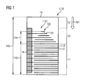
- the piezoelectric actuator 1 is a piezoelectric actuator with a total stack 10 in monolithic multilayer construction.
- the piezoelectric actuator 1 has a piezoelectrically active partial stack 11 with piezoceramic layers 111 arranged alternately one above the other with lead zirconate titanate (PZT) as piezoceramic material and electrode layers 112 made of a silver-palladium alloy.
- PZT lead zirconate titanate
- a piezoelectrically inactive termination region 12 in the form of a ceramic cover package of ceramic layers is arranged.
- the transition region stack 13 has transition metal piezoceramic layers 131 and transition region electrode layers 132 arranged alternately one above the other.
- the piezoceramic material of the transition region piezoceramic layers and the piezoceramic material of the piezoceramic layers of the piezoelectrically active sub-stack 11 are the same. In an alternative embodiment, the piezoceramic materials are different.
- the electrode material of the transition region electrode layers corresponds to that of the electrode layers of the piezoelectrically active sub-stack. Alternatively, different electrode materials are used.
- the piezoelectrically active partial stack 11, the transition region stack 13 and the termination region 12 together form a monolithic total stack 10.
- an outer metallization 14 On one side surface of the overall stack in the region of the active sub-stack 11 and in the region of the transition region stack 13 is an outer metallization 14 for electrical contacting of the respective Electrode layers attached. For alternate contacting another, not shown outer metallization is present.
- the total height 103 of the total stack 10 in the stacking direction 101 is 30 mm.
- the partial stack height 113 piezoelectrically active sub-stack 11 is about 10 mm.
- the transition portion stacking height 114 of the transition region stack 13 is about 2 mm.
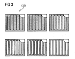
- transition-region piezoceramic layers 131 and the transition-region electrode layers 132 are configured and arranged against one another such that in the stacking direction 133 of the transition-region stack 13 from transition-region piezoceramic layer to transition-region piezoceramic layer, one piezoelectrically active surface per transitional piezoceramic layer is successively changed. This is achieved by changing the lateral dimension 1323 of the transition region electrode layers. Along the lateral extent 1322 of the transition region electrode layers, the dimension 1323 changes.
- the transition region electrode layers 132 have a comb-like structure. This comb-like structure 1321 is in FIG. 3 indicated.
- the comb-like structure 1321 of the transition-region electrode layers 132 is successively changed. As in FIG. 3 As indicated, a distance between lands of the comb-like structure 1321 is changed from transition-region electrode layer to transition-region electrode layer. Adjacent transition region electrode layers 132 together form an interdigital structure 1121, respectively.
- This new piezoelectric actuator 1 is used to control an injection valve of an engine of a motor vehicle.
Landscapes
- Engineering & Computer Science (AREA)
- Manufacturing & Machinery (AREA)
- Fuel-Injection Apparatus (AREA)
- General Electrical Machinery Utilizing Piezoelectricity, Electrostriction Or Magnetostriction (AREA)
- Oscillators With Electromechanical Resonators (AREA)
- Piezo-Electric Or Mechanical Vibrators, Or Delay Or Filter Circuits (AREA)
- Piezo-Electric Transducers For Audible Bands (AREA)
- Measuring Fluid Pressure (AREA)
Abstract
Description
Die Erfindung betrifft einen Piezoaktor in monolithischer Vielschichtbauweise, aufweisend mindestens einen piezoelektrisch aktiven Teilstapel, wobei der Teilstapel übereinander angeordnete Piezokeramikschichten mit piezokeramischem Werkstoff und zwischen den Piezokeramikschichten angeordnete Elektrodenschichten (Innenelektroden) aufweist, mindestens einen, über dem piezoelektrisch aktiven Teilstapel angeordneten piezoelektrisch inaktiven Abschlussbereich und mindestens einen zwischen dem piezoelektrisch aktiven Teilstapel und dem Abschlussbereich angeordneten Übergangsbereich, wobei der piezoelektrisch aktive Teilstapel, der Abschlussbereich und der Übergangsbereich zu einem monolithischen Gesamtstapel miteinander verbunden sind. Neben dem Piezoaktor wird eine Verwendung des Piezoaktors angegeben.The invention relates to a piezoelectric actuator in a monolithic multilayer construction, comprising at least one piezoelectrically active partial stack, wherein the partial stack comprises piezoceramic material arranged piezoceramic material and arranged between the piezoceramic layers electrode layers (internal electrodes), at least one, arranged on the piezoelectrically active part stacking piezoelectrically inactive termination area and at least a transition region arranged between the piezoelectrically active partial stack and the termination region, the piezoelectrically active partial stack, the termination region and the transition region being connected to one another in a monolithic overall stack. In addition to the piezoelectric actuator, a use of the piezoelectric actuator is specified.
Die
Die
Bei der erstmaligen elektrischen Ansteuerung solcher Piezoaktoren bis in den Großsignalbereich (Feldstärken von mehreren kV/mm) wird der piezokeramische Werkstoff gepolt. Dabei resultiert eine irreversible Längenänderung, die so genannte remanente Dehnung. Aufgrund der remanenten Dehnung und aufgrund einer zusätzlichen Dehnung, die bei elektrischer Ansteuerung der Elektrodenschichten im Betrieb des Piezoaktors auftritt, entstehen im Gesamtstapel Zugspannungen. Diese Zugspannungen führen dazu, dass im Verlauf der Polung oder im Betrieb des Piezoaktors beispielsweise entlang einer Grenzfläche zwischen einer Piezokeramikschicht und einer Elektrodenschicht Risse (Polungsrisse) entstehen. Solche Risse treten insbesondere auch im Übergangsbereich zwischen aktivem Teilstapel und Abschlussbereich auf. Besonders schädlich sind dabei sich verzweigende oder sich in Längsrichtung des Gesamtstapels ausbreitende Risse. Solche Risse führen unweigerlich zu vorzeitigem Ausfall des Piezoaktors.During the first electrical actuation of such piezo actuators up to the large signal range (field strengths of several kV / mm), the piezoceramic material is poled. This results in an irreversible change in length, the so-called remanent strain. Due to the remanent elongation and due to an additional elongation, which occurs during electrical activation of the electrode layers during operation of the piezoelectric actuator, tensile stresses arise in the overall stack. These tensile stresses cause cracks (poling cracks) to form in the course of the poling or in the operation of the piezoactuator, for example along an interface between a piezoceramic layer and an electrode layer. Such cracks also occur, in particular, in the transition region between the active partial stack and the termination region. Particularly damaging are branching cracks or spreading in the longitudinal direction of the total pile. Such cracks inevitably lead to premature failure of the piezoelectric actuator.
Aufgabe der Erfindung ist es, einen Piezoaktor anzugeben, bei dem die Wahrscheinlichkeit für die Bildung der oben beschriebenen Risse und deren Wachstum im Vergleich zum Stand der Technik verringert ist.The object of the invention is to provide a piezoelectric actuator in which the probability for the formation of the cracks described above and their growth is reduced compared to the prior art.
Zur Lösung der Aufgabe wird ein Piezoaktor in monolithischer Vielschichtbauweise angegeben, aufweisend die Merkmale des Patentanspruchs 1.To solve the problem, a piezoelectric actuator in a monolithic multilayer construction is specified, comprising the features of claim 1.
Der Abschlussbereich kann ein Kopf- oder Fußbereich des Gesamtstapels sein. Der Abschlussbereich kann aus einer Schicht oder aus mehreren Schichten bestehen. Im letzteren Fall wird von einem Deckpaket gesprochen. Als Material des Abschlussbereichs kommen keramische oder metallische Materialien in Frage.The termination area may be a header or footer of the entire stack. The completion area can consist of one or more layers. In the latter case is spoken by a cover package. As a material of the termination ceramic or metallic materials come into question.
Ein piezokeramischer Werkstoff der Piezokeramikschichten und ein piezokeramischer Werkstoff der Übergangsbereichs-Piezokeramikschichten können gleich sein. Es können aber auch unterschiedliche Werkstoffe verwendet werden. Ebenso können die Schichtdicken dieser Schichten gleich oder unterschiedlich sein.A piezoceramic material of the piezoceramic layers and a piezoceramic material of the transition region piezoceramic layers may be the same. But it can also different materials are used. Likewise, the layer thicknesses of these layers may be the same or different.
Die grundlegende Idee der Erfindung besteht darin, einen Übergangsbereich mit Gradierung der Struktur der Übergangsbereichs-Elektrodenschichten bereitzustellen. Durch die Gradierung ändert sich die piezoelektrisch aktive Fläche und damit das piezoelektrisch aktive Volumen von Piezokeramikschicht zu Piezokeramikschicht. Durch die Gradierung werden die aus dem Stand der Technik bekannten hohen Zugspannungen zwischen piezoelektrisch aktivem Teilstapel und piezoelektrisch inaktivem Abschlussbereich deutlich reduziert.The basic idea of the invention is to provide a transition region grading the structure of the transition region electrode layers. The gradation changes the piezoelectrically active surface and thus the piezoelectrically active volume from the piezoceramic layer to the piezoceramic layer. The grading significantly reduces the high tensile stresses known from the prior art between the piezoelectrically active partial stack and the piezoelectrically inactive termination region.
Durch die Änderung der Struktur wird eine Änderung der während des Polarisierens oder während des Betriebs auftretenden Dehnung bewirkt. Die resultierende Dehnung in der lateralen Richtung (a/b-Richtung) und die resultierende Dehnung in der Stapelrichtung (c-Richtung) setzen sich nicht mehr rein aus den d31(negativ)- und d33(positiv)-Anteilen zusammen. Es resultiert eine Überlagerung dieser Effekte. Bei bestimmten Richtungen eines Polungs- und Ansteuervektors zu den Schichtebenen wird eine minimale Dehnung in den jeweiligen Richtungen erreicht. Dies führt zu entsprechend geringen mechanischen Zugspannungen zwischen zwei Schichten des Übergangsbereichs.The change in structure causes a change in the strain occurring during polarization or during operation. The resulting strain in the lateral direction (a / b direction) and the resulting strain in the stacking direction (c direction) are no longer purely composed of the d 31 (negative) and d 33 (positive) components. This results in a superposition of these effects. In certain directions of a poling and driving vector to the layer planes, minimal elongation in the respective directions is achieved. This leads to correspondingly low mechanical tensile stresses between two layers of the transition region.
Gemäß einer besonderen Ausgestaltung weist der aktive Teilstapel und/oder der Abschlussbereich eine aus dem Bereich von einschließlich 1 mm bis einschließlich 10 mm und insbesondere aus dem Bereich von einschließlich 3 mm bis einschließlich 5 mm ausgewählte Teilstapelhöhe aufweist. Beispielsweise beträgt die Teilstapelhöhe 2 mm. Es hat sich gezeigt, dass mit diesen Teilstapelhöhen Spannungsspitzen sehr gut abgebaut werden. Gemäß einer besonderen Ausgestaltung weist der Übergangsbereichs-Teilstapel eine aus dem Bereich von einschließlich 0,2 bis einschließlich 5,0 mm und insbesondere von einschließlich 0,5 bis einschließlich 2,0 mm ausgewählte Übergangsstapelhöhe auf. Mit den Teilstapeln sind sehr hohe Gesamtstapel zugänglich. In einer besonderen Ausgestaltung weist der Gesamtstapel eine Gesamtstapelhöhe auf, die aus dem Bereich von einschließlich 10 mm bis einschließlich 200 mm ausgewählt ist. Höhere Gesamtstapelhöhen sind ebenfalls zugänglich.According to a particular embodiment, the active partial stack and / or the termination region has a partial stack height selected from the range of 1 mm to 10 mm inclusive and in particular from the range of 3 mm to 5 mm inclusive. For example, the partial stack height is 2 mm. It has been shown that with these partial stack heights stress peaks are reduced very well. According to a particular embodiment, the transition region partial stack has a range of from 0.2 to 5.0 mm inclusive and, in particular, from 0.5 to 2.0 mm inclusive, selected transition stack height. With the sub-stacks very high total stacks are accessible. In a particular embodiment, the total stack has a total stack height selected from the range of 10 mm to 200 mm inclusive. Higher overall stack heights are also accessible.
Dieser neue, zuverlässige Piezoaktor wird bevorzugt zur Ansteuerung eines Ventils und insbesondere eines Einspritzventils einer Brennkraftmaschine verwendet. Die Brennkraftmaschine ist beispielsweise ein Motor eines Kraftfahrzeugs.This new, reliable piezoelectric actuator is preferably used to control a valve and in particular an injection valve of an internal combustion engine. The internal combustion engine is for example an engine of a motor vehicle.
Anhand mehrerer Ausführungsbeispiele und der dazugehörigen Figuren wird die Erfindung im Folgenden näher beschrieben. Die Figuren sind schematisch und stellen keine maßstabsgetreuen Abbildungen dar.
- Figur 1
- zeigt einen Piezoaktor in monolithischer Vielschichtbauweise von der Seite.
- Figur 2A
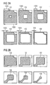
- zeigt eine nicht erfindungsgemäße sukzessive Änderung der Struktur der Übergangsbereichs-Elektrodenschichten.
- Figur 2B
- zeigt eine weitere nicht erfindungsgemäße sukzessive Änderung der Struktur der Übergangsbereichs-Elektrodenschichten
- Figur 3
- zeigt eine sukzessive Änderung der kammartigen Struktur der Übergangsbereichs-Elektrodenschichten.
- FIG. 1
- shows a piezoelectric actuator in monolithic multilayer construction of the side.
- FIG. 2A
- shows a non-inventive successive change in the structure of the transition region electrode layers.
- FIG. 2B
- shows a further non-inventive successive change in the structure of the transition region electrode layers
- FIG. 3
- shows a successive change of the comb-like structure of the transition region electrode layers.
Der Piezoaktor 1 ist ein Piezoaktor mit einem Gesamtstapel 10 in monolithischer Vielschichtbauweise. Der Piezoaktor 1 weist einen piezoelektrisch aktiven Teilstapel 11 mit alternierend übereinander angeordneten Piezokeramikschichten 111 mit Bleizirkonattitanat (PZT) als piezokeramischem Werkstoff und Elektrodenschichten 112 aus einer Silber-Palladium-Legierung auf.The piezoelectric actuator 1 is a piezoelectric actuator with a
Über dem piezoelektrisch aktiven Teilstapel 11 ist ein piezoelektrisch inaktiver Abschlussbereich 12 in Form eines keramischen Deckpakets aus keramischen Schichten angeordnet.Above the piezoelectrically active
Zwischen dem piezoelektrisch aktiven Teilstapel 11 und dem Deckpaket 12 ist ein Übergangsbereich 13 in Form eines Übergangsbereichs-Stapels angeordnet. Der Übergangsbereichs-Stapel 13 weist alternierend übereinander angeordnete Übergangsbereichs-Piezokeramikschichten 131 und Übergangsbereichs-Elektrodenschichten 132 auf. Der piezokeramische Werkstoff der Übergangsbereichs-Piezokeramikschichten und der piezokeramische Werkstoff der Piezokeramikschichten des piezoelektrisch aktiven Teilstapels 11 sind gleich. In einer alternativen Ausgestaltung sind die piezokeramischen Werkstoffe unterschiedlich. Das Elektrodenmaterial der Übergangsbereichs-Elektrodenschichten entspricht dem der Elektrodenschichten des piezoelektrisch aktiven Teil-Stapels. Alternativ werden unterschiedliche Elektrodenmaterialien verwendet.Between the piezoelectrically active
Der piezoelektrisch aktive Teilstapel 11, der Übergangsbereichs-Stapel 13 und der Abschlussbereich 12 bilden zusammen einem monolithischen Gesamtstapel 10. An einer Seitenfläche des Gesamtstapels im Bereich des aktiven Teilstapels 11 und im Bereich des Übergangsbereichs-Stapels 13 ist eine Außenmetallisierung 14 zur elektrischen Kontaktierung der jeweiligen Elektrodenschichten angebracht. Zur alternierenden Kontaktierung ist eine weitere, nicht dargestellte Außenmetallisierung vorhanden.The piezoelectrically active
Die Gesamthöhe 103 des Gesamtstapels 10 in Stapelrichtung 101 beträgt.30 mm. Die Teilstapelhöhe 113 piezoelektrisch aktiven Teilstapels 11 beträgt etwa 10 mm. Die Übergangsbereichs-Teilstapelhöhe 114 des Übergangsbereichs-Stapels 13 beträgt etwa 2 mm.The
Die Übergangsbereichs-Piezokeramikschichten 131 und die Übergangsbereichs-Elektrodenschichten 132 sind derart ausgestaltet und aneinander angeordnet, dass in Stapelrichtung 133 des Übergangsbereichs-Stapels 13 von Übergangsbereichs-Piezokeramikschicht zu Übergangsbereichs-Piezokeramikschicht sukzessive eine piezoelektrisch aktive Fläche pro Übergangs-Piezokeramikschicht geändert wird. Dies wird durch Änderung der lateralen Abmessung 1323 der Übergangsbereichs-Elektrodenschichten erreicht. Entlang der lateralen Ausdehnung 1322 der Übergangsbereichs-Elektrodenschichten ändert sich die Abmessung 1323.The transition-region piezoceramic layers 131 and the transition-region electrode layers 132 are configured and arranged against one another such that in the stacking direction 133 of the transition-
Die Übergangsbereichs-Elektrodenschichten 132 weisen eine kammartige Struktur auf. Diese kammartige Struktur 1321 ist in
Dem gemäß wird die kammartige Struktur 1321 der Übergangsbereichs-Elektrodenschichten 132 sukzessive geändert. Wie in
Weitere Ausführungsbeispiele ergeben sich dadurch, dass nicht nur bzw. alternativ zur dargestellten Anordnung des Abschlussbereichs 12 und des Übergangsbereichs 13 im Kopfbereich des Gesamtstapels 10 der Abschlussbereich 12 und der Übergangsbereich im Fußbereich des Gesamtstapels 10 angeordnet wird.Further exemplary embodiments result from the fact that not only or alternatively to the illustrated arrangement of the
Dieser neue Piezoaktor 1 wird zur Ansteuerung eines Einspritzventils eines Motors eines Kraftfahrzeugs verwendet.This new piezoelectric actuator 1 is used to control an injection valve of an engine of a motor vehicle.
Claims (6)
- Piezo actuator (1) in a monolithic multilayered design, having- at least one piezoelectrically active stack (11), where the stack comprises stacked piezoceramic layers (111, 121) and electrode layers (112, 122) arranged between the piezoceramic layers,- at least one piezoelectrically inactive terminating region (12) arranged above the piezoelectrically active stack, and- at least one transition region (13) arranged between the piezoelectrically active stack and the terminating region, where- the piezoelectrically active stack, the terminating region and the transition region are joined together to form a monolithic total stack (10),- the transition region comprises stacked transition-region piezoceramic layers (131) and transition-region electrode layers (132) arranged between the transition-region piezoceramic layers, and- the transition-region piezoceramic layers and the transition-region electrode layers are in a form and are arranged on one another such that from transition-region piezoceramic layer to transition-region piezoceramic layer in the stack direction of the transition region, one piezoelectrically active area per transition piezoceramic layer is successively changed,
characterised in that- a structure of the respective transition-region electrode layer parallel to its lateral dimension (1322) is formed like a comb. - Piezo actuator according to claim 1, wherein adjacent transition-region electrode layers form an interdigital structure (1121).
- Piezo actuator according to claim 1 or 2, wherein the active sub-stack and/or the terminating region has a sub-stack height (113) selected from the range 1 mm to 10 mm inclusive, and in particular one from the range 3 mm to 5 mm inclusive.
- Piezo actuator according to any of claims 1 to 3, wherein the transition region sub-stack has a transition-stack height (114) selected from the range 0.2 mm to 5.0 mm inclusive, and in particular from 0.5 mm to 2.0 mm inclusive.
- Piezo actuator according to any of claims 1 to 4, wherein the total stack has a total-stack height (103) that is selected from the range 10 mm to 200 mm inclusive.
- Use of a piezo actuator according to any of claims 1 to 5 for operating a valve, and in particular an injection valve of an internal combustion engine.
Applications Claiming Priority (2)
| Application Number | Priority Date | Filing Date | Title |
|---|---|---|---|
| DE102005034814 | 2005-07-26 | ||
| PCT/EP2006/007406 WO2007012485A1 (en) | 2005-07-26 | 2006-07-26 | Monolithic piezo actuator with a change in the electrode structure in the junction region, and use of the piezo actuator |
Publications (2)
| Publication Number | Publication Date |
|---|---|
| EP1908129A1 EP1908129A1 (en) | 2008-04-09 |
| EP1908129B1 true EP1908129B1 (en) | 2012-12-26 |
Family
ID=37072255
Family Applications (3)
| Application Number | Title | Priority Date | Filing Date |
|---|---|---|---|
| EP06762840A Not-in-force EP1908129B1 (en) | 2005-07-26 | 2006-07-26 | Monolithic piezo actuator with a change in the electrode structure in the junction region, and use of the piezo actuator |
| EP06762839A Active EP1908131B1 (en) | 2005-07-26 | 2006-07-26 | Method for producing a monolithic piezo actuator with stack elements, monilithic piezo actuator with stack elements, and use of the piezo actuator |
| EP06777989A Not-in-force EP1908132B1 (en) | 2005-07-26 | 2006-07-26 | Monolithic piezoactuator with rotation of the polarisation in the transition region and use of said piezoactuator |
Family Applications After (2)
| Application Number | Title | Priority Date | Filing Date |
|---|---|---|---|
| EP06762839A Active EP1908131B1 (en) | 2005-07-26 | 2006-07-26 | Method for producing a monolithic piezo actuator with stack elements, monilithic piezo actuator with stack elements, and use of the piezo actuator |
| EP06777989A Not-in-force EP1908132B1 (en) | 2005-07-26 | 2006-07-26 | Monolithic piezoactuator with rotation of the polarisation in the transition region and use of said piezoactuator |
Country Status (6)
| Country | Link |
|---|---|
| US (4) | US7679274B2 (en) |
| EP (3) | EP1908129B1 (en) |
| JP (3) | JP5260286B2 (en) |
| AT (2) | ATE448573T1 (en) |
| DE (2) | DE502006004677D1 (en) |
| WO (3) | WO2007012654A1 (en) |
Families Citing this family (26)
| Publication number | Priority date | Publication date | Assignee | Title |
|---|---|---|---|---|
| DE50015994D1 (en) * | 1999-12-16 | 2010-10-28 | Epcos Ag | Nt |
| CN101694865B (en) * | 2004-03-09 | 2013-03-20 | 京瓷株式会社 | Multilayer piezoelectric element and its manufacturing method |
| US7786652B2 (en) * | 2004-03-29 | 2010-08-31 | Kyocera Corporation | Multi-layer piezoelectric element |
| DE112005001022B4 (en) * | 2005-01-06 | 2014-08-21 | Murata Manufacturing Co., Ltd. | Method for producing a piezoelectric actuator and piezoelectric actuator |
| EP1908129B1 (en) * | 2005-07-26 | 2012-12-26 | Siemens Aktiengesellschaft | Monolithic piezo actuator with a change in the electrode structure in the junction region, and use of the piezo actuator |
| DE102006049892A1 (en) * | 2006-10-23 | 2008-05-08 | Siemens Ag | Monolithic piezo actuator with transition zone and safety layer as well as use of the piezo actuator |
| JP5025661B2 (en) * | 2006-12-15 | 2012-09-12 | 京セラ株式会社 | Multilayer piezoelectric element, injection device including the same, and fuel injection system |
| DE102007005341A1 (en) | 2007-02-02 | 2008-08-07 | Epcos Ag | Multi-layer component and method for producing a multilayer component |
| EP1978567B1 (en) * | 2007-02-19 | 2014-06-25 | Continental Automotive GmbH | Piezoceramic multilayer actuator and method of manufacturing a piezoceramic multilayer actuator |
| ATE535946T1 (en) * | 2007-02-19 | 2011-12-15 | Siemens Ag | PIEZOCERAMIC MULTI-LAYER ACTUATOR AND METHOD FOR PRODUCING A PIEZOCERAMIC MULTI-LAYER ACTUATOR |
| ATE528802T1 (en) * | 2007-02-19 | 2011-10-15 | Siemens Ag | PIEZO-CERAMIC MULTI-LAYER ACTUATOR AND PRODUCTION METHOD THEREOF |
| EP2248197A1 (en) | 2008-01-28 | 2010-11-10 | Technion Research & Development Foundation LTD. | Piezoelectric-ferroelectric actuator device |
| DE102008011414A1 (en) * | 2008-02-27 | 2009-09-10 | Continental Automotive Gmbh | Method for polarizing a piezoceramic |
| WO2010110291A1 (en) * | 2009-03-25 | 2010-09-30 | 京セラ株式会社 | Layered piezoelectric element, injection device utilizing same, and fuel injection system |
| TWI406436B (en) * | 2009-07-10 | 2013-08-21 | Ind Tech Res Inst | Stacked-type piezoelectric device and method for manufacturing the same |
| DE102010027845A1 (en) * | 2010-04-16 | 2011-10-20 | Robert Bosch Gmbh | Piezoelectric actuator |
| JP5403170B2 (en) * | 2010-11-01 | 2014-01-29 | 株式会社村田製作所 | Multilayer piezoelectric actuator and piezoelectric vibration device |
| JP5825656B2 (en) * | 2011-02-28 | 2015-12-02 | 株式会社日本セラテック | Piezoelectric actuator and coupled piezoelectric actuator |
| JP6047317B2 (en) * | 2012-06-29 | 2016-12-21 | 日本特殊陶業株式会社 | Piezoelectric element |
| DE102012107343B4 (en) * | 2012-08-09 | 2018-11-22 | Epcos Ag | Method for polarity of a multilayer component |
| US9579691B2 (en) | 2013-05-21 | 2017-02-28 | Mplus Co., Ltd. | Piezoelectric element and electronic component including the same |
| CN105612626B (en) * | 2013-10-11 | 2018-01-05 | 株式会社村田制作所 | Cascade type thermoelectric conversion element |
| JP2017184297A (en) * | 2016-03-28 | 2017-10-05 | セイコーエプソン株式会社 | Piezoelectric actuator, piezoelectric motor, robot, hand and pump |
| US20190035562A1 (en) | 2017-05-26 | 2019-01-31 | Flash Power Capacitors, Llc | High energy density capacitor system and method |
| WO2018218164A1 (en) | 2017-05-26 | 2018-11-29 | Flash Power Capacitors, Llc | High energy density capacitor and wireless charging system |
| EP3631825A4 (en) * | 2017-05-26 | 2021-03-17 | Flash Power Capacitors, LLC | CAPACITOR WITH HIGH ENERGY DENSITY AND WIRELESS CHARGING SYSTEM |
Family Cites Families (30)
| Publication number | Priority date | Publication date | Assignee | Title |
|---|---|---|---|---|
| JPH0730165B2 (en) | 1986-12-26 | 1995-04-05 | 住友化学工業株式会社 | Epoxy resin composition |
| JPH01226186A (en) * | 1988-03-07 | 1989-09-08 | Fuji Electric Co Ltd | Laminated piezoelectric element |
| JPH02163983A (en) * | 1988-12-16 | 1990-06-25 | Toyota Motor Corp | Polarization treatment of laminated body for laminated ceramic piezoelectric element use |
| JP2893741B2 (en) * | 1989-08-02 | 1999-05-24 | 日本電気株式会社 | Electrostrictive effect element |
| JPH04214686A (en) * | 1990-10-05 | 1992-08-05 | Nec Corp | Electrostrictive effect element |
| JPH04159785A (en) * | 1990-10-23 | 1992-06-02 | Nec Corp | Electrostrictive effect element |
| US5345137A (en) * | 1991-04-08 | 1994-09-06 | Olympus Optical Co., Ltd. | Two-dimensionally driving ultrasonic motor |
| JPH0730165A (en) * | 1993-07-12 | 1995-01-31 | Murata Mfg Co Ltd | Multilayer piezoelectric element |
| JPH11186626A (en) * | 1997-12-25 | 1999-07-09 | Kyocera Corp | Multilayer piezoelectric actuator |
| JPH11284240A (en) * | 1998-03-30 | 1999-10-15 | Kyocera Corp | Multilayer piezoelectric actuator |
| JP2000133852A (en) * | 1998-10-28 | 2000-05-12 | Sumitomo Metal Ind Ltd | Multilayer piezoelectric element and method of manufacturing the same |
| DE19928178A1 (en) * | 1999-06-19 | 2000-08-10 | Bosch Gmbh Robert | Piezoactuator e.g. for valve, has multilayer construction of piezo layers, intermediate electrodes, alternating lateral electrode contacting, and division of multilayer structure into sub-actuators |
| JP2002054526A (en) * | 2000-05-31 | 2002-02-20 | Denso Corp | Piezoelectric element for injector |
| EP1160885B1 (en) * | 2000-05-31 | 2010-08-18 | Denso Corporation | Piezoelectric device for injector |
| DE10164326A1 (en) * | 2000-12-28 | 2002-10-31 | Denso Corp | Integrally fired, layered electromechanical conversion element |
| DE10202574A1 (en) * | 2001-02-15 | 2002-09-12 | Ceramtec Ag | Piezoceramic multi-layer actuator with a transition area between the active area and the inactive head and foot areas |
| JP2002299706A (en) * | 2001-03-28 | 2002-10-11 | Nec Tokin Corp | Multilayer piezoelectric actuator |
| JP2003347614A (en) * | 2002-05-30 | 2003-12-05 | Nec Tokin Corp | Stacked piezoelectric actuator |
| JP2004274029A (en) * | 2003-02-19 | 2004-09-30 | Denso Corp | Piezoelectric actuator |
| DE10307825A1 (en) | 2003-02-24 | 2004-09-09 | Epcos Ag | Electrical multilayer component and layer stack |
| JP2004297041A (en) | 2003-03-12 | 2004-10-21 | Denso Corp | Stacked piezoelectric element |
| JP4258238B2 (en) | 2003-03-13 | 2009-04-30 | 株式会社デンソー | Multilayer piezoelectric element and method for manufacturing the same |
| JP4438321B2 (en) * | 2003-06-02 | 2010-03-24 | 株式会社デンソー | Manufacturing method of multilayer piezoelectric element |
| JP4686975B2 (en) * | 2003-09-26 | 2011-05-25 | 株式会社村田製作所 | Multilayer piezoelectric element and manufacturing method thereof |
| DE102004031402A1 (en) * | 2004-06-29 | 2006-02-09 | Siemens Ag | Piezoelectric component with predetermined breaking point, method for producing the component and use of the component |
| JP4876467B2 (en) * | 2004-12-06 | 2012-02-15 | 株式会社デンソー | Multilayer piezoelectric element |
| DE112005001022B4 (en) * | 2005-01-06 | 2014-08-21 | Murata Manufacturing Co., Ltd. | Method for producing a piezoelectric actuator and piezoelectric actuator |
| DE102005002980B3 (en) * | 2005-01-21 | 2006-09-07 | Siemens Ag | Monolithic multilayer actuator and method for its production |
| JP2006303044A (en) * | 2005-04-18 | 2006-11-02 | Denso Corp | Multilayer piezoelectric element |
| EP1908129B1 (en) * | 2005-07-26 | 2012-12-26 | Siemens Aktiengesellschaft | Monolithic piezo actuator with a change in the electrode structure in the junction region, and use of the piezo actuator |
-
2006
- 2006-07-26 EP EP06762840A patent/EP1908129B1/en not_active Not-in-force
- 2006-07-26 EP EP06762839A patent/EP1908131B1/en active Active
- 2006-07-26 JP JP2008523241A patent/JP5260286B2/en not_active Expired - Fee Related
- 2006-07-26 US US11/996,601 patent/US7679274B2/en not_active Expired - Fee Related
- 2006-07-26 JP JP2008523358A patent/JP5069233B2/en not_active Expired - Fee Related
- 2006-07-26 JP JP2008523242A patent/JP2009503828A/en active Pending
- 2006-07-26 WO PCT/EP2006/064682 patent/WO2007012654A1/en not_active Ceased
- 2006-07-26 WO PCT/EP2006/007406 patent/WO2007012485A1/en not_active Ceased
- 2006-07-26 AT AT06762839T patent/ATE448573T1/en active
- 2006-07-26 DE DE502006004677T patent/DE502006004677D1/en active Active
- 2006-07-26 EP EP06777989A patent/EP1908132B1/en not_active Not-in-force
- 2006-07-26 US US11/996,573 patent/US7545080B2/en not_active Expired - Fee Related
- 2006-07-26 AT AT06777989T patent/ATE441215T1/en active
- 2006-07-26 US US11/996,603 patent/US20080203853A1/en not_active Abandoned
- 2006-07-26 WO PCT/EP2006/007405 patent/WO2007012484A1/en not_active Ceased
- 2006-07-26 DE DE502006005359T patent/DE502006005359D1/en active Active
-
2011
- 2011-02-21 US US13/031,398 patent/US20110138593A1/en not_active Abandoned
Also Published As
| Publication number | Publication date |
|---|---|
| EP1908132B1 (en) | 2009-08-26 |
| EP1908132A1 (en) | 2008-04-09 |
| JP2009503827A (en) | 2009-01-29 |
| US7679274B2 (en) | 2010-03-16 |
| US20080203853A1 (en) | 2008-08-28 |
| DE502006005359D1 (en) | 2009-12-24 |
| WO2007012654A1 (en) | 2007-02-01 |
| EP1908129A1 (en) | 2008-04-09 |
| US20080203857A1 (en) | 2008-08-28 |
| US20110138593A1 (en) | 2011-06-16 |
| JP2009503828A (en) | 2009-01-29 |
| EP1908131B1 (en) | 2009-11-11 |
| US20080185938A1 (en) | 2008-08-07 |
| DE502006004677D1 (en) | 2009-10-08 |
| JP2009503834A (en) | 2009-01-29 |
| JP5260286B2 (en) | 2013-08-14 |
| WO2007012485A1 (en) | 2007-02-01 |
| ATE441215T1 (en) | 2009-09-15 |
| WO2007012484A1 (en) | 2007-02-01 |
| US7545080B2 (en) | 2009-06-09 |
| ATE448573T1 (en) | 2009-11-15 |
| JP5069233B2 (en) | 2012-11-07 |
| EP1908131A1 (en) | 2008-04-09 |
Similar Documents
| Publication | Publication Date | Title |
|---|---|---|
| EP1908129B1 (en) | Monolithic piezo actuator with a change in the electrode structure in the junction region, and use of the piezo actuator | |
| EP1597780B1 (en) | Electrical multilayered component and layer stack | |
| DE102005015112B4 (en) | Monolithic piezoelectric component with mechanical decoupling layer, method for manufacturing the component and use of the component | |
| DE19860001C2 (en) | Piezoelectric component, method for its production and use of such a component | |
| EP1636859A1 (en) | Piezoelectric component with a predetermined breaking point, method for producing the component and use of the component | |
| DE102004031404B4 (en) | Piezoelectric component with predetermined breaking point and electrical connection element, method for producing the component and use of the component | |
| EP1233461B1 (en) | Piezoceramic multilayer actuator having a transition zone between the active zone and the inactive head and foot zone | |
| DE102007015457A1 (en) | Piezoelectric component with security layer and method for its production | |
| EP2319102B1 (en) | Piezoactuator with a weak-point layer | |
| DE102007015446A1 (en) | Piezoelectric device with security layer and infiltration barrier and method for its production | |
| EP1384272B1 (en) | Additional contacting for an electric component and piezoelectric component in the form of a multilayer structure | |
| WO2009106410A1 (en) | Method for polarizing a piezoceramic material | |
| EP2082445B1 (en) | Monolithic piezoactuator with transition region and safety layer and use of the piezoactuator | |
| EP1233462A2 (en) | Multilayer actuator with shifted contact areas of internal electrodes having the same polarization to their external electrode | |
| DE102004007999A1 (en) | Piezoelectric actuator for injector in IC engine of vehicle, has piezoelectric element units, each with stack of not more than 50 piezoelectric ceramic layers, and inactive bonded ceramic layers between electrode layers | |
| DE112010002244T5 (en) | Piezoelectric stacked actuator assembly | |
| DE102005002980B3 (en) | Monolithic multilayer actuator and method for its production | |
| DE102006001656A1 (en) | Piezoelectric actuator and method for producing the same | |
| EP2071645B1 (en) | Piezo actuator module with a multiple structure of Piezo elements | |
| DE102005052714B4 (en) | Piezoelectric actuator and method for producing the same | |
| DE102009020238A1 (en) | Piezo actuator with electrical contacting pins | |
| DE102010030652A1 (en) | Piezoelectric actuator for fuel injector of common-rail injection system of internal combustion engine, has piezo element with discontinuous material property and structure property arranged between passive and active piezo elements | |
| WO2014009303A1 (en) | Piezoelectric multilayer actuator and injection valve | |
| WO2017028985A1 (en) | Piezoelectric component |
Legal Events
| Date | Code | Title | Description |
|---|---|---|---|
| PUAI | Public reference made under article 153(3) epc to a published international application that has entered the european phase |
Free format text: ORIGINAL CODE: 0009012 |
|
| 17P | Request for examination filed |
Effective date: 20071221 |
|
| AK | Designated contracting states |
Kind code of ref document: A1 Designated state(s): AT BE BG CH CY CZ DE DK EE ES FI FR GB GR HU IE IS IT LI LT LU LV MC NL PL PT RO SE SI SK TR |
|
| 17Q | First examination report despatched |
Effective date: 20080616 |
|
| GRAP | Despatch of communication of intention to grant a patent |
Free format text: ORIGINAL CODE: EPIDOSNIGR1 |
|
| DAX | Request for extension of the european patent (deleted) | ||
| GRAS | Grant fee paid |
Free format text: ORIGINAL CODE: EPIDOSNIGR3 |
|
| GRAA | (expected) grant |
Free format text: ORIGINAL CODE: 0009210 |
|
| AK | Designated contracting states |
Kind code of ref document: B1 Designated state(s): AT BE BG CH CY CZ DE DK EE ES FI FR GB GR HU IE IS IT LI LT LU LV MC NL PL PT RO SE SI SK TR |
|
| REG | Reference to a national code |
Ref country code: GB Ref legal event code: FG4D Free format text: NOT ENGLISH |
|
| REG | Reference to a national code |
Ref country code: CH Ref legal event code: EP |
|
| REG | Reference to a national code |
Ref country code: AT Ref legal event code: REF Ref document number: 590866 Country of ref document: AT Kind code of ref document: T Effective date: 20130115 |
|
| REG | Reference to a national code |
Ref country code: DE Ref legal event code: R096 Ref document number: 502006012361 Country of ref document: DE Effective date: 20130228 |
|
| RAP2 | Party data changed (patent owner data changed or rights of a patent transferred) |
Owner name: SIEMENS AKTIENGESELLSCHAFT |
|
| PG25 | Lapsed in a contracting state [announced via postgrant information from national office to epo] |
Ref country code: LT Free format text: LAPSE BECAUSE OF FAILURE TO SUBMIT A TRANSLATION OF THE DESCRIPTION OR TO PAY THE FEE WITHIN THE PRESCRIBED TIME-LIMIT Effective date: 20121226 Ref country code: SE Free format text: LAPSE BECAUSE OF FAILURE TO SUBMIT A TRANSLATION OF THE DESCRIPTION OR TO PAY THE FEE WITHIN THE PRESCRIBED TIME-LIMIT Effective date: 20121226 Ref country code: FI Free format text: LAPSE BECAUSE OF FAILURE TO SUBMIT A TRANSLATION OF THE DESCRIPTION OR TO PAY THE FEE WITHIN THE PRESCRIBED TIME-LIMIT Effective date: 20121226 |
|
| REG | Reference to a national code |
Ref country code: LT Ref legal event code: MG4D |
|
| REG | Reference to a national code |
Ref country code: NL Ref legal event code: VDEP Effective date: 20121226 |
|
| PG25 | Lapsed in a contracting state [announced via postgrant information from national office to epo] |
Ref country code: GR Free format text: LAPSE BECAUSE OF FAILURE TO SUBMIT A TRANSLATION OF THE DESCRIPTION OR TO PAY THE FEE WITHIN THE PRESCRIBED TIME-LIMIT Effective date: 20130327 Ref country code: SI Free format text: LAPSE BECAUSE OF FAILURE TO SUBMIT A TRANSLATION OF THE DESCRIPTION OR TO PAY THE FEE WITHIN THE PRESCRIBED TIME-LIMIT Effective date: 20121226 Ref country code: LV Free format text: LAPSE BECAUSE OF FAILURE TO SUBMIT A TRANSLATION OF THE DESCRIPTION OR TO PAY THE FEE WITHIN THE PRESCRIBED TIME-LIMIT Effective date: 20121226 |
|
| PG25 | Lapsed in a contracting state [announced via postgrant information from national office to epo] |
Ref country code: EE Free format text: LAPSE BECAUSE OF FAILURE TO SUBMIT A TRANSLATION OF THE DESCRIPTION OR TO PAY THE FEE WITHIN THE PRESCRIBED TIME-LIMIT Effective date: 20121226 Ref country code: ES Free format text: LAPSE BECAUSE OF FAILURE TO SUBMIT A TRANSLATION OF THE DESCRIPTION OR TO PAY THE FEE WITHIN THE PRESCRIBED TIME-LIMIT Effective date: 20130406 Ref country code: SK Free format text: LAPSE BECAUSE OF FAILURE TO SUBMIT A TRANSLATION OF THE DESCRIPTION OR TO PAY THE FEE WITHIN THE PRESCRIBED TIME-LIMIT Effective date: 20121226 Ref country code: BG Free format text: LAPSE BECAUSE OF FAILURE TO SUBMIT A TRANSLATION OF THE DESCRIPTION OR TO PAY THE FEE WITHIN THE PRESCRIBED TIME-LIMIT Effective date: 20130326 Ref country code: CZ Free format text: LAPSE BECAUSE OF FAILURE TO SUBMIT A TRANSLATION OF THE DESCRIPTION OR TO PAY THE FEE WITHIN THE PRESCRIBED TIME-LIMIT Effective date: 20121226 Ref country code: IS Free format text: LAPSE BECAUSE OF FAILURE TO SUBMIT A TRANSLATION OF THE DESCRIPTION OR TO PAY THE FEE WITHIN THE PRESCRIBED TIME-LIMIT Effective date: 20130426 |
|
| PG25 | Lapsed in a contracting state [announced via postgrant information from national office to epo] |
Ref country code: PL Free format text: LAPSE BECAUSE OF FAILURE TO SUBMIT A TRANSLATION OF THE DESCRIPTION OR TO PAY THE FEE WITHIN THE PRESCRIBED TIME-LIMIT Effective date: 20121226 Ref country code: PT Free format text: LAPSE BECAUSE OF FAILURE TO SUBMIT A TRANSLATION OF THE DESCRIPTION OR TO PAY THE FEE WITHIN THE PRESCRIBED TIME-LIMIT Effective date: 20130426 Ref country code: RO Free format text: LAPSE BECAUSE OF FAILURE TO SUBMIT A TRANSLATION OF THE DESCRIPTION OR TO PAY THE FEE WITHIN THE PRESCRIBED TIME-LIMIT Effective date: 20121226 Ref country code: NL Free format text: LAPSE BECAUSE OF FAILURE TO SUBMIT A TRANSLATION OF THE DESCRIPTION OR TO PAY THE FEE WITHIN THE PRESCRIBED TIME-LIMIT Effective date: 20121226 |
|
| PG25 | Lapsed in a contracting state [announced via postgrant information from national office to epo] |
Ref country code: DK Free format text: LAPSE BECAUSE OF FAILURE TO SUBMIT A TRANSLATION OF THE DESCRIPTION OR TO PAY THE FEE WITHIN THE PRESCRIBED TIME-LIMIT Effective date: 20121226 |
|
| PLBE | No opposition filed within time limit |
Free format text: ORIGINAL CODE: 0009261 |
|
| STAA | Information on the status of an ep patent application or granted ep patent |
Free format text: STATUS: NO OPPOSITION FILED WITHIN TIME LIMIT |
|
| PG25 | Lapsed in a contracting state [announced via postgrant information from national office to epo] |
Ref country code: CY Free format text: LAPSE BECAUSE OF FAILURE TO SUBMIT A TRANSLATION OF THE DESCRIPTION OR TO PAY THE FEE WITHIN THE PRESCRIBED TIME-LIMIT Effective date: 20121226 |
|
| 26N | No opposition filed |
Effective date: 20130927 |
|
| PG25 | Lapsed in a contracting state [announced via postgrant information from national office to epo] |
Ref country code: IT Free format text: LAPSE BECAUSE OF FAILURE TO SUBMIT A TRANSLATION OF THE DESCRIPTION OR TO PAY THE FEE WITHIN THE PRESCRIBED TIME-LIMIT Effective date: 20121226 |
|
| REG | Reference to a national code |
Ref country code: DE Ref legal event code: R097 Ref document number: 502006012361 Country of ref document: DE Effective date: 20130927 |
|
| BERE | Be: lapsed |
Owner name: SIEMENS A.G. Effective date: 20130731 |
|
| PG25 | Lapsed in a contracting state [announced via postgrant information from national office to epo] |
Ref country code: MC Free format text: LAPSE BECAUSE OF FAILURE TO SUBMIT A TRANSLATION OF THE DESCRIPTION OR TO PAY THE FEE WITHIN THE PRESCRIBED TIME-LIMIT Effective date: 20121226 |
|
| REG | Reference to a national code |
Ref country code: CH Ref legal event code: PL |
|
| REG | Reference to a national code |
Ref country code: IE Ref legal event code: MM4A |
|
| PG25 | Lapsed in a contracting state [announced via postgrant information from national office to epo] |
Ref country code: BE Free format text: LAPSE BECAUSE OF NON-PAYMENT OF DUE FEES Effective date: 20130731 Ref country code: CH Free format text: LAPSE BECAUSE OF NON-PAYMENT OF DUE FEES Effective date: 20130731 Ref country code: LI Free format text: LAPSE BECAUSE OF NON-PAYMENT OF DUE FEES Effective date: 20130731 |
|
| PG25 | Lapsed in a contracting state [announced via postgrant information from national office to epo] |
Ref country code: IE Free format text: LAPSE BECAUSE OF NON-PAYMENT OF DUE FEES Effective date: 20130726 |
|
| REG | Reference to a national code |
Ref country code: AT Ref legal event code: MM01 Ref document number: 590866 Country of ref document: AT Kind code of ref document: T Effective date: 20130726 |
|
| PG25 | Lapsed in a contracting state [announced via postgrant information from national office to epo] |
Ref country code: AT Free format text: LAPSE BECAUSE OF NON-PAYMENT OF DUE FEES Effective date: 20130726 |
|
| PG25 | Lapsed in a contracting state [announced via postgrant information from national office to epo] |
Ref country code: TR Free format text: LAPSE BECAUSE OF FAILURE TO SUBMIT A TRANSLATION OF THE DESCRIPTION OR TO PAY THE FEE WITHIN THE PRESCRIBED TIME-LIMIT Effective date: 20121226 |
|
| PG25 | Lapsed in a contracting state [announced via postgrant information from national office to epo] |
Ref country code: LU Free format text: LAPSE BECAUSE OF NON-PAYMENT OF DUE FEES Effective date: 20130726 Ref country code: HU Free format text: LAPSE BECAUSE OF FAILURE TO SUBMIT A TRANSLATION OF THE DESCRIPTION OR TO PAY THE FEE WITHIN THE PRESCRIBED TIME-LIMIT; INVALID AB INITIO Effective date: 20060726 |
|
| REG | Reference to a national code |
Ref country code: DE Ref legal event code: R081 Ref document number: 502006012361 Country of ref document: DE Owner name: CONTINENTAL AUTOMOTIVE GMBH, DE Free format text: FORMER OWNER: SIEMENS AKTIENGESELLSCHAFT, 80333 MUENCHEN, DE |
|
| REG | Reference to a national code |
Ref country code: FR Ref legal event code: PLFP Year of fee payment: 11 |
|
| REG | Reference to a national code |
Ref country code: GB Ref legal event code: 732E Free format text: REGISTERED BETWEEN 20160901 AND 20160907 |
|
| REG | Reference to a national code |
Ref country code: FR Ref legal event code: TP Owner name: CONTINENTAL AUTOMOTIVE GMBH, DE Effective date: 20160909 |
|
| REG | Reference to a national code |
Ref country code: FR Ref legal event code: PLFP Year of fee payment: 12 |
|
| REG | Reference to a national code |
Ref country code: FR Ref legal event code: PLFP Year of fee payment: 13 |
|
| PGFP | Annual fee paid to national office [announced via postgrant information from national office to epo] |
Ref country code: DE Payment date: 20180731 Year of fee payment: 13 Ref country code: FR Payment date: 20180725 Year of fee payment: 13 |
|
| PGFP | Annual fee paid to national office [announced via postgrant information from national office to epo] |
Ref country code: GB Payment date: 20180719 Year of fee payment: 13 |
|
| REG | Reference to a national code |
Ref country code: DE Ref legal event code: R119 Ref document number: 502006012361 Country of ref document: DE |
|
| GBPC | Gb: european patent ceased through non-payment of renewal fee |
Effective date: 20190726 |
|
| PG25 | Lapsed in a contracting state [announced via postgrant information from national office to epo] |
Ref country code: GB Free format text: LAPSE BECAUSE OF NON-PAYMENT OF DUE FEES Effective date: 20190726 Ref country code: DE Free format text: LAPSE BECAUSE OF NON-PAYMENT OF DUE FEES Effective date: 20200201 |
|
| PG25 | Lapsed in a contracting state [announced via postgrant information from national office to epo] |
Ref country code: FR Free format text: LAPSE BECAUSE OF NON-PAYMENT OF DUE FEES Effective date: 20190731 |