EP1978569B1 - Piezoceramic multilayer actuator and method of manufacturing a piezoceramic multilayer actuator - Google Patents
Piezoceramic multilayer actuator and method of manufacturing a piezoceramic multilayer actuator Download PDFInfo
- Publication number
- EP1978569B1 EP1978569B1 EP07003447A EP07003447A EP1978569B1 EP 1978569 B1 EP1978569 B1 EP 1978569B1 EP 07003447 A EP07003447 A EP 07003447A EP 07003447 A EP07003447 A EP 07003447A EP 1978569 B1 EP1978569 B1 EP 1978569B1
- Authority
- EP
- European Patent Office
- Prior art keywords
- piezoceramic
- particles
- layers
- security layer
- layer
- Prior art date
- Legal status (The legal status is an assumption and is not a legal conclusion. Google has not performed a legal analysis and makes no representation as to the accuracy of the status listed.)
- Not-in-force
Links
Images
Classifications
-
- H—ELECTRICITY
- H10—SEMICONDUCTOR DEVICES; ELECTRIC SOLID-STATE DEVICES NOT OTHERWISE PROVIDED FOR
- H10N—ELECTRIC SOLID-STATE DEVICES NOT OTHERWISE PROVIDED FOR
- H10N30/00—Piezoelectric or electrostrictive devices
- H10N30/50—Piezoelectric or electrostrictive devices having a stacked or multilayer structure
- H10N30/508—Piezoelectric or electrostrictive devices having a stacked or multilayer structure adapted for alleviating internal stress, e.g. cracking control layers
-
- H—ELECTRICITY
- H10—SEMICONDUCTOR DEVICES; ELECTRIC SOLID-STATE DEVICES NOT OTHERWISE PROVIDED FOR
- H10N—ELECTRIC SOLID-STATE DEVICES NOT OTHERWISE PROVIDED FOR
- H10N30/00—Piezoelectric or electrostrictive devices
- H10N30/01—Manufacture or treatment
- H10N30/05—Manufacture of multilayered piezoelectric or electrostrictive devices, or parts thereof, e.g. by stacking piezoelectric bodies and electrodes
- H10N30/053—Manufacture of multilayered piezoelectric or electrostrictive devices, or parts thereof, e.g. by stacking piezoelectric bodies and electrodes by integrally sintering piezoelectric or electrostrictive bodies and electrodes
-
- H—ELECTRICITY
- H10—SEMICONDUCTOR DEVICES; ELECTRIC SOLID-STATE DEVICES NOT OTHERWISE PROVIDED FOR
- H10N—ELECTRIC SOLID-STATE DEVICES NOT OTHERWISE PROVIDED FOR
- H10N30/00—Piezoelectric or electrostrictive devices
- H10N30/80—Constructional details
- H10N30/85—Piezoelectric or electrostrictive active materials
- H10N30/853—Ceramic compositions
- H10N30/8548—Lead based oxides
- H10N30/8554—Lead zirconium titanate based
Definitions
- the present invention refers to a piezoceramic multilayer actuator and a method of manufacturing a piezoceramic multilayer actuator.
- Piezoceramic multilayer actuators convert electrical signals to mechanical operation.
- a voltage applied to electrodes of the piezoceramic multilayer actuator causes the actuator to change its length due to piezoelectric properties of a multitude of piezoceramic layers.
- the inner electrodes and the piezoceramic layers are alternatingly arranged in a stack. Every other inner electrode is electrically conductively connected to a first outer electrode, and every other inner electrode is electrically conductively connected to a second outer electrode.
- Each piezoceramic layer is arranged between one inner electrode connected to the first outer electrode and one inner electrode connected to the second outer electrode.
- Piezoceramic multilayer actuators like this are used to drive or control mechanics, fluids etc. Fuel injectors for combustion engines are an important application.
- a large voltage is applied to the piezoceramic multilayer actuator.
- This large voltage polarizes the piezoceramic layers and causes a remanent deformation of the piezoceramic layers.
- every other inner electrode does not completely extend to the edges of the adjacent piezoceramic layers but is isolated from the outer electrode. This causes inhomogeneous electrical fields within the piezoceramic layers and an inhomogeneous remanent distortion as well as inhomogeneous distortions during the normal operation of the actuator. Any inhomogeneous distortion as well as any imperfection of the piezoceramic multilayer actuator causes mechanical strain and stress within the actuator.
- WO 2006/000479 A1 discloses a piezoceramic multilayer actuator and a method for manufacturing the piezoceramic actuator.
- At least one of the inner electrodes acts as a predetermined breaking point.
- the predetermined breaking point leads to the formation of a defined crack.
- plastic spheres are mixed with a metal paste.
- the resulting paste mixture is applied on a ceramic green sheet.
- the stacking with other ceramic green sheets leads to a green stack. While sintering the green stack the plastic spheres burn out resulting in pores within the according inner electrode. This pores degrade the mechanical strength of the inner electrode.
- the present invention is based on the idea to weaken, or degrade, or impair the mechanical connection between a piezoceramic layer and an adjacent security layer or between two neighbouring piezoceramic layers across a security layer by means of particles introduced into a matrix material of the security layer.
- the particles do not form ceramic bridges between piezoceramic layers wherein the ceramic bridges strengthen or sustain the cohesion of the piezoceramic layers and the entire stack. Rather, the particles are chemically inert and do not chemically react with the piezoceramic material or with the matrix material of the security layer and, after firing, there is a low adhesion between the particles and the piezoceramic material or between the particles and the matrix material of the security layer.
- the particles do react with the piezoceramic material and/or with the matrix material of the security layer but, after firing, the adhesion between the particles and the piezoceramic material is low or the adhesion between the particles and the matrix material of the security layer is low.
- a low adhesion means no adhesion or essentially no adhesion or an adhesion which is weaker than the adhesion between the piezoceramic layers and the matrix material of the security layer.
- the low adhesion between the particles and the piezoceramic material and/or between the particles and the matrix material of the security layer weakens the mechanical linkage between a piezoceramic layer and the adjacent security layer or the mechanical linkage between two piezoceramic layers via a security layer.
- the size of each particle preferably essentially equals or is slightly larger than the thickness of the security layer.
- the material of the particles is more brittle than the piezoceramic material and more brittle than the matrix material of the security layer.
- This brittleness of the particles may be an original property of the particles or may result from a conversion of the material of the particles during firing due to a chemical reaction and/or due to diffusion of components from the piezoceramic material or from the matrix material of the security layer to the particles or vice versa.
- a chemical reaction includes any kind of chemical reaction or chemical conversion from one chemical configuration to another chemical configuration and any kind of integration of diffused or originally present components, or atoms, into lattice sites or interstitial sites of a crystal lattice or a polycrystalline or amorphous phase.
- any alteration of the crystal structure shall be included, for example driving water of crystallisation out of the crystal.
- the particles locally increase the brittleness and/or reduce the cohesion of the piezoceramic material and/or of the matrix material of the security layer in the vicinity of the particles.
- This increase of brittleness and/or reduction of cohesion of the piezoceramic material can appear during firing due to a chemical reaction and/or diffusion of components from the piezoceramic material or from the matrix material to the particles or vice versa.
- water of crystallisation can diffuse from the particles to the piezoceramic material to the matrix material or to the piezoceramic material or vice versa thereby altering the crystal structure.
- This shrinkage is for example due to a phase change or an alteration of the crystal structure during the process of firing which is not reversed during cooling down after the process of firing.
- the densification and/or sintering behaviour of the matrix material of the security layer or of a thin layer of the piezoceramic material at the interface between the piezoceramic layer and the security layer are modified or altered by a diffusion of components or elements and/or a chemical reaction. In this way, the adhesion between the security layer and the piezoceramic layers can be reduced.
- the creation of a PbPdO-phase at the interfaces between the security layer and the piezoceramic layers can be influenced.
- the PZT can separate or unmix into PbTiO 3 and ZrO 2 and TiO 2 thereby destroying the microstructure and considerably reducing the cohesion of the PZT.
- a growth of the particles during firing and/or different thermal expansion coefficients of the particles and the matrix material of the security layer cause the production and growth of tension forces or microcracks during firing and/or when the stack is cooled down.
- the above described mechanisms and measures weaken the mechanical connection or linkage between a piezoceramic layer and an adjacent security layer or between two piezoceramic layers via a security layer.
- a security layer or an interface between the security layer and an adjacent piezoceramic layer form a predetermined breaking point.
- Mechanical strain causes the formation and growth of a crack within the security layer or along the interface between the security layer and the piezoceramic layer.
- a piezoceramic multilayer actuator comprises sub-stacks, each sub-stack comprising a predetermined number of piezoceramic layers and a corresponding number of inner electrodes.
- the inventive security layers are arranged between the sub-stacks. Mechanical strain induces cracks within the security electrodes but most probably not within the sub-stacks. Therefore, the operation and action of the sub-stacks is guaranteed and the reliability of the whole piezoceramic multilayer actuator is increased.
- all the inner electrodes can be provided as security layers, in particular when the particles do not weaken the cohesion of the security layer but the adhesion of the security layer to the piezoceramic layers.
- the matrix material of the security layer is electrically conductive.
- a further advantage of the present invention is that the particles can be easily introduced into the security layer.
- TiO 2 , ZrTiO 2 Ce 2 O 3 and La 2 O 3 and other inorganic materials are examples for appropriate materials of the particles.
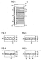
- Fig. 1 is a schematic representation of a piezoceramic multilayer actuator 10 comprising a plurality of piezoceramic layers 12, a plurality of first inner electrodes 16 and a plurality of second inner electrodes 18.
- the piezoceramic layers 12 comprise a piezoceramic first material sintered at a sintering temperature and providing a piezoelectric effect.
- the first inner electrodes 16 are electrically conductively connected to a first outer electrode 22, and the second inner electrodes 18 are electrically conductively connected to a second outer electrode not displayed in Fig. 1 .
- the first inner electrodes 16 are electrically insulated from the second outer electrode, and the second inner electrodes 18 are electrically insulated from the first outer electrode 22.
- Groups of piezoceramic layers 12 and inner electrodes 16, 18 form sub-stacks 24.
- Security layers 20 are arranged between the sub-stacks 24.
- Top and bottom of the piezoceramic multilayer actuator 10 are covered by top and bottom layers 14.
- each of the Figs. 2 to 6 displays a schematic representation of a section of a part of a piezoceramic multilayer actuator, wherein the section is perpendicular to the piezoceramic layers 12, to the inner electrodes 16, 18 and to the security layer 20.
- each of the Figs. 2 to 6 displays merely one security layer and two adjacent piezoceramic layers
- each of the piezoceramic multilayer actuators can comprise any number of piezoceramic layers, any number of inner electrodes and any number of security layers.
- the security layer can be electrically insulating or electrically conductive. In the latter case, the security layer can serve as inner electrode or all inner electrodes of the piezoceramic multilayer actuator can be security layers.
- the security layer 20 comprises a matrix material 32 and particles 30 at least partially embedded in the matrix material 32.
- the diameter of each particle 30 essentially equals or is slightly bigger than the thickness of the security layer 20.
- a mixture of the matrix material 32 and the particles 30 is laminated between green sheets.
- a green stack comprising a plurality of green sheets, a plurality of electrode layers and the mixture of the matrix material 32 and the particles 30 sandwiched between green sheets is then heated to an elevated temperature for a predetermined period of time.
- the green sheets are converted to the piezoceramic layers 12
- the electrode layers are converted to the inner electrodes 16, 18 and the mixture of the matrix material 32 and the particles 30 is converted to the security layer 20.
- the thin gaps 34 may be produced in several alternative ways.
- the particles 30 are shrinking during the process of firing while the matrix material 32 is not shrinking or is growing, or a shrinkage of the particles 30 is stronger than a shrinkage of the matrix material 32, or the matrix material 32 is growing more than the particles 30.
- Any shrinkage of the particles 30 or the matrix material 32 may be due to a densification or sintering of the respective material and/or to a diffusion of components from the respective material to the vicinity.
- the diffusion of chemical components of the particles 30 from the particles 30 to the adjacent green layer or to the matrix material 32 may cause a shrinkage of the particles 30 and/or a growth of the matrix material 32 or the green layer.
- This shrinkage is for example due to a phase change or an alteration of the crystal structure during the process of firing which is not reversed during cooling down after the process of firing.
- the thin gaps 34 are produced during cooling down the stack after the process of firing.
- any material with a positive thermal expansion coefficient shrinks.
- the thermal expansion coefficient of the particles 30 is bigger than the thermal expansion coefficient of the matrix material 32, the particles 30 shrink more than the matrix material 32 and the gaps 34 can emerge.
- Fig. 3 shows a schematic view of a section of a part of another piezoceramic multilayer actuator.
- a security layer 20 between two piezoceramic layers 12 comprises a matrix material 32 and particles 30 at least partially embedded in the matrix material 32.
- the diameters of the particles 30 essentially equal the thickness of the security layer 20.
- Gaps 36 are arranged between the matrix material 32 and the piezoceramic layers 12.
- the security layer 20 is produced by laminating a mixture of the matrix material 32 and the particles 30 between green sheets. In a firing process similar to the firing process described above with reference to Fig. 2 , the green sheets are converted to the piezoceramic layers 12.
- the gaps 36 emerge during the process of firing when the matrix material 32 is shrinking more than the particles 30, or when the particles 30 are growing more than the matrix material 32, or when the particles 30 are growing while the matrix material 32 is shrinking. Alternatively or additionally, the gaps 36 emerge or grow after the process of firing when the thermal expansion coefficient of the matrix material 32 exceeds the thermal expansion coefficient of the particles 30. Irrespective of whether the gaps primarily emerge during or after the process of firing, the formation of the gaps 36 is facilitated by a low adhesion or no adhesion between the matrix material 32 and the green sheets and the piezoceramic layers 12.
- Fig. 4 displays a schematic view of a part of a section through another piezoceramic multilayer actuator.
- a security layer 20 between piezoceramic layers 12 comprises a matrix material 32 and particles 30 at least partially embedded in the matrix material 32.
- the particles 30 comprise a glass or any other brittle material which is more brittle and/or less ductile than the matrix material 32 and the material of piezoceramic layers 12. Therefore, mechanical stress or strain within the piezoceramic multilayer actuator during or after the process of firing or during normal operation of the actuator causes cracks 40 to emerge in the particles 30. The formation of the cracks 40 can be facilitated by a low cohesion within the particles 30.
- Each of the high brittleness and the low cohesion may be an original property of the particles 30 or result from a conversion of the material of the particles 30 during a firing process.
- the size and shape of the gaps 34, 36 and the cracks 40, respectively, may deviate from those displayed in the Figs. 2 to 4 .
- the gaps 34 of the piezoceramic multilayer actuator described above with reference to Fig. 2 can be more or less shifted with reference to the interface between the particles 30 and the piezoceramic layer 12.
- the gaps 34 can at least partially be (slightly) shifted away from the piezoceramic layer 12 and into the particles 30.
- the gaps 34 can at least partially be (slightly) shifted away from the particles 30 and into the piezoceramic layers 12. Furthermore, the gaps 34 can at least partially extend along the interfaces between the particles 30 and the matrix material 32 or along the interfaces between the matrix material 32 and the piezoceramic layers 12. In any case, a gap 34 not necessarily forms at each and every interface between a particle 30 and a piezoceramic layer 12.
- the gaps 36 may be shifted away from the interfaces between the matrix material 32 and the piezoceramic layers 12. For example when the cohesion within the piezoceramic layers 12 is weaker than the adhesion between the matrix material 32 and the piezoceramic layers 12, the gaps 36 can at least partially be (slightly) shifted into the piezoceramic layers 12. For example when the adhesion between the matrix material 32 and the piezoceramic layers 12 is stronger than the cohesion within the matrix material 32, the gaps 36 can at least partially be (slightly) shifted into the matrix material 32. Furthermore, the gaps 36 can at least partially extend along the interfaces between the particles 30 and the matrix material 32 or along the interfaces between the particles 30 and the piezoceramic layers 12.
- the cracks 40 can extend beyond the interfaces between the particles 30 and the matrix material 32 into the matrix material 32.
- the cracks 40 do not extend beyond the interfaces between the particles 30 and the piezoceramic layers 12 into the piezoceramic layers 12.
- the effective total interface area between the security layer and an adjacent piezoceramic layer is reduced, thereby reducing the total effective cohesion between the security layer and the adjacent piezoceramic layer.
- Fig. 5 displays a schematic view of a part of a section through another piezoceramic multilayer actuator.
- a security layer 20 between piezoceramic layers 12 comprises a matrix material 32 and particles 30 at least partially embedded in the matrix material 32.
- the materials of the particles 30 and the piezoceramic layers 12 provide a low adhesion or no adhesion between the particles 30 and the piezoceramic layers 12 at interfaces 42 between the particles 30 and the piezoceramic layers 12.
- This low adhesion may be originally present in a green stack comprising green layers which are converted to the security layer 20 and to the piezoceramic layers 12 in a subsequent firing process.
- the low adhesion may emerge during the process of firing due to diffusion of components between the particles 30, the matrix material 32 and the piezoceramic layers 12 and/or due to chemical alterations of the particles 30 and/or the piezoceramic layers 12 in the adjacencies of the interfaces 42 between the particles 30 and the piezoceramic layers 12.
- the low adhesion may emerge during the process of firing due to a phase change or an alteration of the crystal structure of the particles 30.
- the particles 30 locally alter the piezoceramic layer 12 material near the interfaces 42 between the particles 30 and the piezoceramic layers 12 and/or near the interfaces between the matrix material 32 and the piezoceramic layers 12. This alteration may be due to the diffusion of components from the piezoceramic layers 12 to the particles 30 or vice versa and/or due to chemical reactions at or near the interfaces 42 between the particles 30 and the piezoceramic layers 12 and the interfaces 44 between the matrix material 32 and the piezoceramic layers 12.
- the piezoceramic layers 12 comprise PZT (Lead Zirconate Titanate, Pb(Zr x Ti 1-x )O 3 ) and the particles 30 are able to absorb lead (Pb), the PZT can be locally unmixed or separated into PbTiO 3 , ZrO 2 and TiO 2 at or near the interfaces between the particles and the piezoceramic layers. Thereby the microstructure of the piezoceramic layers 12 is locally destroyed, the brittleness can be increased and the ductility can be reduced.
- PZT Lead Zirconate Titanate, Pb(Zr x Ti 1-x )O 3
- the particles 30 are able to absorb lead (Pb)
- the PZT can be locally unmixed or separated into PbTiO 3 , ZrO 2 and TiO 2 at or near the interfaces between the particles and the piezoceramic layers.
- the microstructure of the piezoceramic layers 12 is locally destroyed, the
- the particles 30 influence the creation of PbPdO-phases at the interfaces 42 between the particles 30 and the piezoceramic layers 12 and/or between the matrix material 32 and the piezoceramic layers 12 thereby reducing the adhesion between the piezoceramic layers 12 and the security layer 20.
- the densification behaviour of the piezoceramic layers 12 or their green predecessors can be locally altered, in an extreme example resulting in an open pore network at the interfaces between the piezoceramic layers 12 and the security layer 20. Ag vapour and/or PbO vapour can infiltrate these open pores.
- the gaps 34, 36, the cracks 40, the low adhesion at interfaces 42, 44, the locally destroyed microstructure or the open pore network weaken the mechanical connection, or linkage, between the piezoceramic layers 12 and the security layers 20.
- the security layer 20 forms a predetermined breaking point similar to a perforation of a writing pad and localizes or restricts the generation or growth of any cracks to the security layer 20.
- Any mechanical strain or stress within the piezoceramic multilayer actuator most probably causes a crack to emerge and grow along the security layer 20. Thereby, the risk that a crack destroys a piezoceramic layer 12 or an inner electrode 16, 18 is largely reduced.
- the diameters of the particles 30 have been described to essentially equal the thickness of the security layers 20. This is advantageous for several aspects and particularly for the formation of gaps 34, 36 as described above with reference to Figs. 2 and 3 .
- Fig. 6 displays a schematic view of a part of a section through a piezoceramic multilayer actuator with a security layer 20 between piezoceramic layers 12.
- the security layer 20 comprises a matrix material 32 and particles 30 at least partially embedded in the matrix material 32.
- the diameters of the particles 30 are smaller or much smaller than the thickness of the security layer 20.
- a high brittleness of the particles 30, a low adhesion between the particles 30 and the matrix material 32 or any influence of the particles on the creation of a PbPdO-phases or on the densification behaviour of the piezoceramic layers 12 in the vicinity of the security layer 20 provides a predetermined breaking point similar to the piezoceramic multilayer actuators described above with reference to Figs. 2 to 5 .
- the security layer is weakened by a diffusion between the particles 30 and the matrix material 32, a chemical reaction of diffused material and/or a phase change or a change of the crystal structure of the particles 30 causing a high brittleness of the particles 30 and/or a low adhesion of the particles 30 to the matrix material 32.
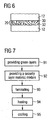
- Fig. 7 shows a schematic flow chart of a method of manufacturing a piezoceramic multilayer actuator.
- a first step 91 a plurality of green sheets or green layers are provided which will be converted to piezoceramic layers in the course of the method.
- a security layer material mixture comprising a second material as a matrix material and particles embedded in the second material is provided. The particles comprise a third material different from the first material and the second material.
- the security layer is laminated between two green layers thereby forming a green stack.
- the green stack is heated first to a debinding temperature and then to a sintering temperature for a predetermined period of time.
- the green layers are converted to the piezoceramic layers comprising the piezoceramic first material.
- the piezoceramic multilayer actuator is cooled down to room temperature or to an even lower temperature.
- the third material is shrinking more than the second material or the second material is growing more than the third material during the fourth step and/or during the fifth step.
- the third material is growing more than the second material or the second material is shrinking more than the third material during the fourth step and/or during the fifth step.
- the third material is preferably chemically altered or converted during the fourth step, thereby increasing its brittleness.
- the diffusion of components from the green layers to the particles or vice versa, or from the matrix material to the particles or vice versa, or from the green layer to the matrix material or vice versa and/or a chemical reaction locally alters the densification behaviour and/or the sintering behaviour of the first material and/or the adhesion between the first material and the second or third material and/or locally increases the brittleness of the first material in the vicinity of the security layer.
- the described mechanisms weakening the security layer can be alternatively consist of or can be assisted by a phase change or an alteration of the crystal structure of the particles 30 during the process of firing.
- the matrix material 32 can be electrically conductive or electrically insulating.
- the security layer can serve as an inner electrode.
- the piezoceramic multilayer actuator comprises a number of sub-stacks mechanically connected to each other via security layers, each sub-stack comprising a number of inner electrodes, all inner electrodes of the piezoceramic multilayer actuator can be security layers as described above with reference to Figs. 2 to 6 .
- the particles preferably comprise TiO 2 , ZrTiO 2 , Ce 2 O 3 or La 2 O 3 or any other electrically insulating or matrix material, other inorganic materials can be advantageous for certain applications, too.
Landscapes
- Engineering & Computer Science (AREA)
- Manufacturing & Machinery (AREA)
- Fuel-Injection Apparatus (AREA)
- Compositions Of Oxide Ceramics (AREA)
Abstract
Description
- The present invention refers to a piezoceramic multilayer actuator and a method of manufacturing a piezoceramic multilayer actuator.
- Piezoceramic multilayer actuators convert electrical signals to mechanical operation. A voltage applied to electrodes of the piezoceramic multilayer actuator causes the actuator to change its length due to piezoelectric properties of a multitude of piezoceramic layers. The inner electrodes and the piezoceramic layers are alternatingly arranged in a stack. Every other inner electrode is electrically conductively connected to a first outer electrode, and every other inner electrode is electrically conductively connected to a second outer electrode. Each piezoceramic layer is arranged between one inner electrode connected to the first outer electrode and one inner electrode connected to the second outer electrode. Piezoceramic multilayer actuators like this are used to drive or control mechanics, fluids etc. Fuel injectors for combustion engines are an important application.
- After manufacture, a large voltage is applied to the piezoceramic multilayer actuator. This large voltage polarizes the piezoceramic layers and causes a remanent deformation of the piezoceramic layers. In the vicinity of the outer electrodes, every other inner electrode does not completely extend to the edges of the adjacent piezoceramic layers but is isolated from the outer electrode. This causes inhomogeneous electrical fields within the piezoceramic layers and an inhomogeneous remanent distortion as well as inhomogeneous distortions during the normal operation of the actuator. Any inhomogeneous distortion as well as any imperfection of the piezoceramic multilayer actuator causes mechanical strain and stress within the actuator. In particular under highly dynamic operating conditions and at high temperatures, cracks at the interfaces between inner electrodes and piezoceramic layers, at the interfaces between the active stack and inactive top or bottom layers and within the piezoceramic layers result. Branching cracks or cracks growing in the stacking direction are particularly detrimental. As soon as a crack electrically insulates a part of an inner electrode, the inhomogenity is further increased and the growth of cracks is accelerated. Furthermore, chemically reactive fluids may intrude into the cracks and chemically destroy the piezoceramic layers and/or the inner electrodes.
-
WO 2006/000479 A1 discloses a piezoceramic multilayer actuator and a method for manufacturing the piezoceramic actuator. At least one of the inner electrodes acts as a predetermined breaking point. In the event of a mechanical overload of the piezoceramic multilayer the predetermined breaking point leads to the formation of a defined crack. In order to get the predetermined breaking point, e.g. plastic spheres are mixed with a metal paste. The resulting paste mixture is applied on a ceramic green sheet. The stacking with other ceramic green sheets leads to a green stack. While sintering the green stack the plastic spheres burn out resulting in pores within the according inner electrode. This pores degrade the mechanical strength of the inner electrode. - It is an object of the present invention to provide a piezoceramic multilayer actuator and a method of manufacturing a piezoceramic multilayer actuator which is more robust.
- This object is achieved by a method according to claim 1 and a piezoceramic multilayer actuator according to claim 11.
- Features of preferred embodiments are defined in the dependent claims.
- The present invention is based on the idea to weaken, or degrade, or impair the mechanical connection between a piezoceramic layer and an adjacent security layer or between two neighbouring piezoceramic layers across a security layer by means of particles introduced into a matrix material of the security layer. The particles do not form ceramic bridges between piezoceramic layers wherein the ceramic bridges strengthen or sustain the cohesion of the piezoceramic layers and the entire stack. Rather, the particles are chemically inert and do not chemically react with the piezoceramic material or with the matrix material of the security layer and, after firing, there is a low adhesion between the particles and the piezoceramic material or between the particles and the matrix material of the security layer. As an alternative, the particles do react with the piezoceramic material and/or with the matrix material of the security layer but, after firing, the adhesion between the particles and the piezoceramic material is low or the adhesion between the particles and the matrix material of the security layer is low.
- Throughout this application, a low adhesion means no adhesion or essentially no adhesion or an adhesion which is weaker than the adhesion between the piezoceramic layers and the matrix material of the security layer.
- The low adhesion between the particles and the piezoceramic material and/or between the particles and the matrix material of the security layer weakens the mechanical linkage between a piezoceramic layer and the adjacent security layer or the mechanical linkage between two piezoceramic layers via a security layer. In both cases, the more particles are comprised in a security layer or the higher the volume fraction of the particles in the security layer is, the weaker is the mechanical linkage between the security layer and the adjacent piezoceramic layers or between the adjacent piezoceramic layers. Therefore, a volume share of at least 5 %, at least 10 %, at least 20 % or at least 40 % is advantageous. In particular in case of a low adhesion between the particles and the piezoceramic material, the size of each particle preferably essentially equals or is slightly larger than the thickness of the security layer.
- Alternatively or additionally to the above described low adhesion, the material of the particles is more brittle than the piezoceramic material and more brittle than the matrix material of the security layer. This brittleness of the particles may be an original property of the particles or may result from a conversion of the material of the particles during firing due to a chemical reaction and/or due to diffusion of components from the piezoceramic material or from the matrix material of the security layer to the particles or vice versa. Throughout this description, a chemical reaction includes any kind of chemical reaction or chemical conversion from one chemical configuration to another chemical configuration and any kind of integration of diffused or originally present components, or atoms, into lattice sites or interstitial sites of a crystal lattice or a polycrystalline or amorphous phase. Furthermore, any alteration of the crystal structure shall be included, for example driving water of crystallisation out of the crystal.
- Alternatively or additionally to the above described low adhesion and/or high brittleness of the particles, the particles locally increase the brittleness and/or reduce the cohesion of the piezoceramic material and/or of the matrix material of the security layer in the vicinity of the particles. This increase of brittleness and/or reduction of cohesion of the piezoceramic material can appear during firing due to a chemical reaction and/or diffusion of components from the piezoceramic material or from the matrix material to the particles or vice versa. For example water of crystallisation can diffuse from the particles to the piezoceramic material to the matrix material or to the piezoceramic material or vice versa thereby altering the crystal structure. This shrinkage is for example due to a phase change or an alteration of the crystal structure during the process of firing which is not reversed during cooling down after the process of firing.
- Preferably, the densification and/or sintering behaviour of the matrix material of the security layer or of a thin layer of the piezoceramic material at the interface between the piezoceramic layer and the security layer are modified or altered by a diffusion of components or elements and/or a chemical reaction. In this way, the adhesion between the security layer and the piezoceramic layers can be reduced.
- In the particular case of a PZT piezoceramic material, the creation of a PbPdO-phase at the interfaces between the security layer and the piezoceramic layers can be influenced. The PZT can separate or unmix into PbTiO3 and ZrO2 and TiO2 thereby destroying the microstructure and considerably reducing the cohesion of the PZT.
- Alternatively or additionally to one or more of the above described mechanisms, a growth of the particles during firing and/or different thermal expansion coefficients of the particles and the matrix material of the security layer cause the production and growth of tension forces or microcracks during firing and/or when the stack is cooled down.
- The above described mechanisms and measures weaken the mechanical connection or linkage between a piezoceramic layer and an adjacent security layer or between two piezoceramic layers via a security layer. In this way, a security layer or an interface between the security layer and an adjacent piezoceramic layer form a predetermined breaking point. Mechanical strain causes the formation and growth of a crack within the security layer or along the interface between the security layer and the piezoceramic layer.
- Preferably a piezoceramic multilayer actuator comprises sub-stacks, each sub-stack comprising a predetermined number of piezoceramic layers and a corresponding number of inner electrodes. The inventive security layers are arranged between the sub-stacks. Mechanical strain induces cracks within the security electrodes but most probably not within the sub-stacks. Therefore, the operation and action of the sub-stacks is guaranteed and the reliability of the whole piezoceramic multilayer actuator is increased.
- As an alternative, all the inner electrodes can be provided as security layers, in particular when the particles do not weaken the cohesion of the security layer but the adhesion of the security layer to the piezoceramic layers. In this case, the matrix material of the security layer is electrically conductive.
- A further advantage of the present invention is that the particles can be easily introduced into the security layer. TiO2, ZrTiO2 Ce2O3 and La2O3 and other inorganic materials are examples for appropriate materials of the particles.
- Some embodiments of the present invention will now be described with reference to the Figures enclosed herewith. In the Figures,
- Fig. 1
- is a schematic representation of a piezoceramic multilayer actuator;
- Fig. 2
- is a schematic representation of a part of the piezoceramic multilayer actuator;
- Fig. 3
- is a schematic representation of a part of a piezoceramic multilayer actuator;
- Fig. 4
- is a schematic representation of a part of a piezoceramic multilayer actuator;
- Fig. 5
- is a schematic representation of a part of a piezoceramic multilayer actuator;
- Fig. 6
- is a schematic representation of a part of a piezoceramic multilayer actuator; and
- Fig. 7
- is a schematic flow chart of the method of manufacturing a piezoceramic multilayer actuator.
-
Fig. 1 is a schematic representation of apiezoceramic multilayer actuator 10 comprising a plurality ofpiezoceramic layers 12, a plurality of firstinner electrodes 16 and a plurality of secondinner electrodes 18. The piezoceramic layers 12 comprise a piezoceramic first material sintered at a sintering temperature and providing a piezoelectric effect. The firstinner electrodes 16 are electrically conductively connected to a firstouter electrode 22, and the secondinner electrodes 18 are electrically conductively connected to a second outer electrode not displayed inFig. 1 . The firstinner electrodes 16 are electrically insulated from the second outer electrode, and the secondinner electrodes 18 are electrically insulated from the firstouter electrode 22. Groups ofpiezoceramic layers 12 andinner electrodes form sub-stacks 24. Security layers 20 are arranged between the sub-stacks 24. Top and bottom of thepiezoceramic multilayer actuator 10 are covered by top and bottom layers 14. - A number of alternative embodiments of the security layers 20 are described subsequently with respect to the
Figs. 2 to 6 . Each of theFigs. 2 to 6 displays a schematic representation of a section of a part of a piezoceramic multilayer actuator, wherein the section is perpendicular to the piezoceramic layers 12, to theinner electrodes security layer 20. Although each of theFigs. 2 to 6 displays merely one security layer and two adjacent piezoceramic layers, each of the piezoceramic multilayer actuators can comprise any number of piezoceramic layers, any number of inner electrodes and any number of security layers. In each of the embodiments, the security layer can be electrically insulating or electrically conductive. In the latter case, the security layer can serve as inner electrode or all inner electrodes of the piezoceramic multilayer actuator can be security layers. - Referring to
Fig. 2 , thesecurity layer 20 comprises amatrix material 32 andparticles 30 at least partially embedded in thematrix material 32. The diameter of eachparticle 30 essentially equals or is slightly bigger than the thickness of thesecurity layer 20. There is athin gap 34 between eachparticle 30 and eachadjacent piezoceramic layer 12. - During manufacture of the piezoceramic multilayer actuator described with reference to
Fig. 2 , a mixture of thematrix material 32 and theparticles 30 is laminated between green sheets. A green stack comprising a plurality of green sheets, a plurality of electrode layers and the mixture of thematrix material 32 and theparticles 30 sandwiched between green sheets is then heated to an elevated temperature for a predetermined period of time. During this debinding and sintering process, or baking process, or firing process, the green sheets are converted to the piezoceramic layers 12, the electrode layers are converted to theinner electrodes matrix material 32 and theparticles 30 is converted to thesecurity layer 20. - During or after the process of firing, the
thin gaps 34 may be produced in several alternative ways. According to a first embodiment, theparticles 30 are shrinking during the process of firing while thematrix material 32 is not shrinking or is growing, or a shrinkage of theparticles 30 is stronger than a shrinkage of thematrix material 32, or thematrix material 32 is growing more than theparticles 30. Any shrinkage of theparticles 30 or thematrix material 32 may be due to a densification or sintering of the respective material and/or to a diffusion of components from the respective material to the vicinity. For example, the diffusion of chemical components of theparticles 30 from theparticles 30 to the adjacent green layer or to thematrix material 32 may cause a shrinkage of theparticles 30 and/or a growth of thematrix material 32 or the green layer. This shrinkage is for example due to a phase change or an alteration of the crystal structure during the process of firing which is not reversed during cooling down after the process of firing. - As an alternative, the
thin gaps 34 are produced during cooling down the stack after the process of firing. When cooling down, any material with a positive thermal expansion coefficient shrinks. When the thermal expansion coefficient of theparticles 30 is bigger than the thermal expansion coefficient of thematrix material 32, theparticles 30 shrink more than thematrix material 32 and thegaps 34 can emerge. - Irrespective of whether the
gaps 34 emerge during or after firing, no adhesion or a low adhesion between theparticles 30 and the green sheets and the piezoceramic layers 12 facilitates the formation of thegaps 34 at the interfaces between theparticles 30 and the piezoceramic layers 12. -
Fig. 3 shows a schematic view of a section of a part of another piezoceramic multilayer actuator. Asecurity layer 20 between twopiezoceramic layers 12 comprises amatrix material 32 andparticles 30 at least partially embedded in thematrix material 32. The diameters of theparticles 30 essentially equal the thickness of thesecurity layer 20. Thus, many or allparticles 30 are in contact with both adjacent piezoceramic layers 12.Gaps 36 are arranged between thematrix material 32 and the piezoceramic layers 12. - The
security layer 20 is produced by laminating a mixture of thematrix material 32 and theparticles 30 between green sheets. In a firing process similar to the firing process described above with reference toFig. 2 , the green sheets are converted to the piezoceramic layers 12. Thegaps 36 emerge during the process of firing when thematrix material 32 is shrinking more than theparticles 30, or when theparticles 30 are growing more than thematrix material 32, or when theparticles 30 are growing while thematrix material 32 is shrinking. Alternatively or additionally, thegaps 36 emerge or grow after the process of firing when the thermal expansion coefficient of thematrix material 32 exceeds the thermal expansion coefficient of theparticles 30. Irrespective of whether the gaps primarily emerge during or after the process of firing, the formation of thegaps 36 is facilitated by a low adhesion or no adhesion between thematrix material 32 and the green sheets and the piezoceramic layers 12. -
Fig. 4 displays a schematic view of a part of a section through another piezoceramic multilayer actuator. Asecurity layer 20 betweenpiezoceramic layers 12 comprises amatrix material 32 andparticles 30 at least partially embedded in thematrix material 32. Theparticles 30 comprise a glass or any other brittle material which is more brittle and/or less ductile than thematrix material 32 and the material of piezoceramic layers 12. Therefore, mechanical stress or strain within the piezoceramic multilayer actuator during or after the process of firing or during normal operation of the actuator causescracks 40 to emerge in theparticles 30. The formation of thecracks 40 can be facilitated by a low cohesion within theparticles 30. - Each of the high brittleness and the low cohesion may be an original property of the
particles 30 or result from a conversion of the material of theparticles 30 during a firing process. - In the piezoceramic multilayer actuators described above with reference to
Figs. 2 to 4 , the size and shape of thegaps cracks 40, respectively, may deviate from those displayed in theFigs. 2 to 4 . In particular, thegaps 34 of the piezoceramic multilayer actuator described above with reference toFig. 2 can be more or less shifted with reference to the interface between theparticles 30 and thepiezoceramic layer 12. For example when the adhesion between thepiezoceramic layer 12 and theparticles 30 is stronger than the cohesion within theparticles 30, thegaps 34 can at least partially be (slightly) shifted away from thepiezoceramic layer 12 and into theparticles 30. For example when the adhesion between theparticles 30 and the piezoceramic layers 12 is stronger than the cohesion within the piezoceramic layers 12, thegaps 34 can at least partially be (slightly) shifted away from theparticles 30 and into the piezoceramic layers 12. Furthermore, thegaps 34 can at least partially extend along the interfaces between theparticles 30 and thematrix material 32 or along the interfaces between thematrix material 32 and the piezoceramic layers 12. In any case, agap 34 not necessarily forms at each and every interface between aparticle 30 and apiezoceramic layer 12. - In the piezoceramic multilayer actuator described above with reference to
Fig. 3 , thegaps 36 may be shifted away from the interfaces between thematrix material 32 and the piezoceramic layers 12. For example when the cohesion within the piezoceramic layers 12 is weaker than the adhesion between thematrix material 32 and the piezoceramic layers 12, thegaps 36 can at least partially be (slightly) shifted into the piezoceramic layers 12. For example when the adhesion between thematrix material 32 and the piezoceramic layers 12 is stronger than the cohesion within thematrix material 32, thegaps 36 can at least partially be (slightly) shifted into thematrix material 32. Furthermore, thegaps 36 can at least partially extend along the interfaces between theparticles 30 and thematrix material 32 or along the interfaces between theparticles 30 and the piezoceramic layers 12. - In the piezoceramic multilayer actuator described above with reference to
Fig. 4 , thecracks 40 can extend beyond the interfaces between theparticles 30 and thematrix material 32 into thematrix material 32. Preferably, thecracks 40 do not extend beyond the interfaces between theparticles 30 and the piezoceramic layers 12 into the piezoceramic layers 12. - In the piezoceramic multilayer actuators described above with reference to the
Figs. 2 to 4 , the effective total interface area between the security layer and an adjacent piezoceramic layer is reduced, thereby reducing the total effective cohesion between the security layer and the adjacent piezoceramic layer. -
Fig. 5 displays a schematic view of a part of a section through another piezoceramic multilayer actuator. Asecurity layer 20 betweenpiezoceramic layers 12 comprises amatrix material 32 andparticles 30 at least partially embedded in thematrix material 32. According to a first variant, the materials of theparticles 30 and thepiezoceramic layers 12 provide a low adhesion or no adhesion between theparticles 30 and thepiezoceramic layers 12 atinterfaces 42 between theparticles 30 and the piezoceramic layers 12. This low adhesion may be originally present in a green stack comprising green layers which are converted to thesecurity layer 20 and to the piezoceramic layers 12 in a subsequent firing process. As an alternative, the low adhesion may emerge during the process of firing due to diffusion of components between theparticles 30, thematrix material 32 and thepiezoceramic layers 12 and/or due to chemical alterations of theparticles 30 and/or thepiezoceramic layers 12 in the adjacencies of theinterfaces 42 between theparticles 30 and the piezoceramic layers 12. As a further alternative, the low adhesion may emerge during the process of firing due to a phase change or an alteration of the crystal structure of theparticles 30. - According to another variant, the
particles 30 locally alter thepiezoceramic layer 12 material near theinterfaces 42 between theparticles 30 and thepiezoceramic layers 12 and/or near the interfaces between thematrix material 32 and the piezoceramic layers 12. This alteration may be due to the diffusion of components from thepiezoceramic layers 12 to theparticles 30 or vice versa and/or due to chemical reactions at or near theinterfaces 42 between theparticles 30 and thepiezoceramic layers 12 and theinterfaces 44 between thematrix material 32 and the piezoceramic layers 12. For example, when thepiezoceramic layers 12 comprise PZT (Lead Zirconate Titanate, Pb(ZrxTi1-x)O3) and theparticles 30 are able to absorb lead (Pb), the PZT can be locally unmixed or separated into PbTiO3, ZrO2 and TiO2 at or near the interfaces between the particles and the piezoceramic layers. Thereby the microstructure of the piezoceramic layers 12 is locally destroyed, the brittleness can be increased and the ductility can be reduced. - As a further variant, the
particles 30 influence the creation of PbPdO-phases at theinterfaces 42 between theparticles 30 and thepiezoceramic layers 12 and/or between thematrix material 32 and thepiezoceramic layers 12 thereby reducing the adhesion between thepiezoceramic layers 12 and thesecurity layer 20. - As a further variant, the densification behaviour of the
piezoceramic layers 12 or their green predecessors can be locally altered, in an extreme example resulting in an open pore network at the interfaces between thepiezoceramic layers 12 and thesecurity layer 20. Ag vapour and/or PbO vapour can infiltrate these open pores. - In all the piezoceramic multilayer actuators described above with reference to
Figs. 2 to 5 , thegaps cracks 40, the low adhesion atinterfaces piezoceramic layers 12 and the security layers 20. In this way, thesecurity layer 20 forms a predetermined breaking point similar to a perforation of a writing pad and localizes or restricts the generation or growth of any cracks to thesecurity layer 20. Any mechanical strain or stress within the piezoceramic multilayer actuator most probably causes a crack to emerge and grow along thesecurity layer 20. Thereby, the risk that a crack destroys apiezoceramic layer 12 or aninner electrode - In the piezoceramic multilayer actuators described above with reference to
Figs. 2 to 5 , the diameters of theparticles 30 have been described to essentially equal the thickness of the security layers 20. This is advantageous for several aspects and particularly for the formation ofgaps Figs. 2 and 3 . - However,
particles 30 smaller or much smaller than the thickness of thesecurity layer 20 can be advantageous, too.
Fig. 6 displays a schematic view of a part of a section through a piezoceramic multilayer actuator with asecurity layer 20 between piezoceramic layers 12. Thesecurity layer 20 comprises amatrix material 32 andparticles 30 at least partially embedded in thematrix material 32. The diameters of theparticles 30 are smaller or much smaller than the thickness of thesecurity layer 20. A high brittleness of theparticles 30, a low adhesion between theparticles 30 and thematrix material 32 or any influence of the particles on the creation of a PbPdO-phases or on the densification behaviour of thepiezoceramic layers 12 in the vicinity of thesecurity layer 20 provides a predetermined breaking point similar to the piezoceramic multilayer actuators described above with reference toFigs. 2 to 5 . In particular, the security layer is weakened by a diffusion between theparticles 30 and thematrix material 32, a chemical reaction of diffused material and/or a phase change or a change of the crystal structure of theparticles 30 causing a high brittleness of theparticles 30 and/or a low adhesion of theparticles 30 to thematrix material 32. -
Fig. 7 shows a schematic flow chart of a method of manufacturing a piezoceramic multilayer actuator. In afirst step 91, a plurality of green sheets or green layers are provided which will be converted to piezoceramic layers in the course of the method. In asecond step 92, a security layer material mixture comprising a second material as a matrix material and particles embedded in the second material is provided. The particles comprise a third material different from the first material and the second material. In athird step 93, the security layer is laminated between two green layers thereby forming a green stack. In afourth step 94, the green stack is heated first to a debinding temperature and then to a sintering temperature for a predetermined period of time. During this firing, or baking, or sintering step, the green layers are converted to the piezoceramic layers comprising the piezoceramic first material. In afifth step 95, the piezoceramic multilayer actuator is cooled down to room temperature or to an even lower temperature. - When the above described method is applied to manufacture a piezoceramic multilayer actuator as described above with reference to
Fig. 2 , the third material is shrinking more than the second material or the second material is growing more than the third material during the fourth step and/or during the fifth step. In order to manufacture a piezoceramic multilayer actuator as described above with reference toFig. 3 , the third material is growing more than the second material or the second material is shrinking more than the third material during the fourth step and/or during the fifth step. In order to manufacture a piezoceramic multilayer actuator as described above with reference toFig. 4 , the third material is preferably chemically altered or converted during the fourth step, thereby increasing its brittleness. In order to manufacture the piezoceramic multilayer actuator as described above with reference toFig. 5 , the diffusion of components (for example lead Pb) from the green layers to the particles or vice versa, or from the matrix material to the particles or vice versa, or from the green layer to the matrix material or vice versa and/or a chemical reaction locally alters the densification behaviour and/or the sintering behaviour of the first material and/or the adhesion between the first material and the second or third material and/or locally increases the brittleness of the first material in the vicinity of the security layer. For all the piezoceramic multilayer actuators described above with reference to theFigs. 2 to 6 , the described mechanisms weakening the security layer can be alternatively consist of or can be assisted by a phase change or an alteration of the crystal structure of theparticles 30 during the process of firing. - In the piezoceramic multilayer actuators described above with reference to the
Figs. 2 to 6 , thematrix material 32 can be electrically conductive or electrically insulating. When the matrix material is electrically conductive, the security layer can serve as an inner electrode. - Although it is preferred that the piezoceramic multilayer actuator comprises a number of sub-stacks mechanically connected to each other via security layers, each sub-stack comprising a number of inner electrodes, all inner electrodes of the piezoceramic multilayer actuator can be security layers as described above with reference to
Figs. 2 to 6 . - Although the particles preferably comprise TiO2, ZrTiO2, Ce2O3 or La2O3 or any other electrically insulating or matrix material, other inorganic materials can be advantageous for certain applications, too.
Claims (12)
- Method of manufacturing a piezoceramic multilayer actuator (10), the method comprising:- providing (91) a plurality of green layers, wherein the green layers are to be converted to piezoceramic layers (12) comprising a piezoceramic first material in a subsequent step of heating;- providing (92) a security layer material mixture comprising a second material (32) and particles (30) embedded in the second material (32), wherein the particles comprise a third material different from the first material and different from the second material,- laminating (93) the security layer material mixture between two piezoceramic layers (12), thereby forming a green stack;- heating (94) the green stack to a sintering temperature, wherein the green layers are converted to the piezoceramic layers (12) and a chemical reaction or a phase change or an alternation of the third material degrades the mechanical connection of the piezoceramic layers (12) by the security layer (20),characterized in that as the third material an inorganic material is used.
- Method as claimed in claim 1, wherein in the step of heating (94), the third material chemically reacts with the first material or with the second material (32) in the vicinity of the particle (30) and mechanically degrades the first or second material, respectively, by increasing the brittleness or reducing the ductility or the cohesion of the first or second material, respectively.
- Method as claimed in one of the preceding claims, wherein the chemical reaction increases the brittleness of the third material or decreases the cohesion of the third material.
- Method as claimed in one of the preceding claims, wherein, in the step of heating, the third material shrinks and/or the second material (32) grows.
- Method as claimed in claim 4, wherein the shrinkage of the particle (30) and/or the growth of the second material (32) causes gaps (34) to evolve between the particles (30) and the piezoceramic layers (12).
- Method as claimed in one of the claims 1 to 3, wherein, in the step of heating, the third material grows and/or the second material (32) shrinks.
- Method as claimed in claim 6, wherein the growth of the particles (30) or the shrinkage of the second material (32) causes gaps (36) to evolve between the second material (32) and the piezoceramic layers (12).
- Method as claimed in one of the preceding claims, wherein the chemical reaction of the third material is a chemical reaction of the third material and the first material at an interface (43) between one of the particles (30) and one of the plurality of piezoceramic layer (12), and wherein the chemical reaction locally increases the brittleness of the first material or reduces the adhesion between the piezoceramic layer (12) and the security layer (20) or locally alters the densification behavior and/or the sintering behavior of the first material.
- Method as claimed in one of the preceding claims, wherein the chemical reaction of the third material is a chemical reaction of the third material and the second material at an interface (46) between one of the particles (30) and the second material (32), and wherein the chemical reaction locally increases the brittleness of the second material or reduces the adhesion between the piezoceramic layer (12) and the security layer (20) or locally reduces the cohesion of the second material (32) or locally alters the densification behavior and/or the sintering behavior of the second material.
- Method as claimed in one of the preceding claims, wherein the first material comprises Pb, and wherein, in the step of heating (94), Pb diffuses from the first material to the third material, thereby locally reducing the cohesion of the first material or the adhesion of the first material to the security layer (20).
- Piezoceramic multilayer actuator (10) comprising:- a plurality of piezoceramic layers (12) comprising a piezoceramic first material sintered at a sintering temperature; and- a security layer (20) disposed between two piezoceramic layer (12);wherein the security layer (20) comprises a second material (32) and particles (30) at least partially embedded in the second material (32), wherein the particles comprise a third material different from the first material and different from the second material,
characterized in that the third material comprise an inorganic material which is more brittle than the first material and the second material or gaps (34, 36) at an interface (42, 44) between the security layer (20) and a piezoceramic layer (12) degrade the mechanical connection of the security layer (20) and the piezoceramic layer (12) or the first material or the second material are locally mechanically degraded at interfaces (42, 46) between the first material or the second material (32), respectively, and the particles (30) . - Piezoceramic multilayer actuator (10) as claimed in claim 11, wherein the third material comprises at least one of TiO2, ZrTiO2, Ce2O3, La2O3.
Priority Applications (4)
| Application Number | Priority Date | Filing Date | Title |
|---|---|---|---|
| EP07003447A EP1978569B1 (en) | 2007-02-19 | 2007-02-19 | Piezoceramic multilayer actuator and method of manufacturing a piezoceramic multilayer actuator |
| AT07003447T ATE535946T1 (en) | 2007-02-19 | 2007-02-19 | PIEZOCERAMIC MULTI-LAYER ACTUATOR AND METHOD FOR PRODUCING A PIEZOCERAMIC MULTI-LAYER ACTUATOR |
| US12/031,385 US7948150B2 (en) | 2007-02-19 | 2008-02-14 | Piezoceramic multilayer actuator and method of manufacturing a piezoceramic multilayer actuator |
| JP2008036915A JP2008270738A (en) | 2007-02-19 | 2008-02-19 | Multilayer piezoceramic actuator and method for manufacturing multilayer piezoceramic actuator |
Applications Claiming Priority (1)
| Application Number | Priority Date | Filing Date | Title |
|---|---|---|---|
| EP07003447A EP1978569B1 (en) | 2007-02-19 | 2007-02-19 | Piezoceramic multilayer actuator and method of manufacturing a piezoceramic multilayer actuator |
Publications (2)
| Publication Number | Publication Date |
|---|---|
| EP1978569A1 EP1978569A1 (en) | 2008-10-08 |
| EP1978569B1 true EP1978569B1 (en) | 2011-11-30 |
Family
ID=38280985
Family Applications (1)
| Application Number | Title | Priority Date | Filing Date |
|---|---|---|---|
| EP07003447A Not-in-force EP1978569B1 (en) | 2007-02-19 | 2007-02-19 | Piezoceramic multilayer actuator and method of manufacturing a piezoceramic multilayer actuator |
Country Status (4)
| Country | Link |
|---|---|
| US (1) | US7948150B2 (en) |
| EP (1) | EP1978569B1 (en) |
| JP (1) | JP2008270738A (en) |
| AT (1) | ATE535946T1 (en) |
Families Citing this family (6)
| Publication number | Priority date | Publication date | Assignee | Title |
|---|---|---|---|---|
| EP2232599B1 (en) * | 2008-01-23 | 2014-12-24 | Epcos AG | Piezoelectric multilayer component |
| JP2011510505A (en) * | 2008-01-23 | 2011-03-31 | エプコス アクチエンゲゼルシャフト | Piezoelectric multilayer components |
| JP5587793B2 (en) * | 2008-01-23 | 2014-09-10 | エプコス アクチエンゲゼルシャフト | Piezoelectric multilayer components |
| EP2461385B1 (en) * | 2009-07-28 | 2016-12-14 | Kyocera Corporation | Multi-layer piezoelectric element, and injection device and fuel injection system using the same |
| DE102010008775A1 (en) * | 2010-02-22 | 2011-08-25 | Epcos Ag, 81669 | Piezoelectric multilayer component and method for producing a piezoelectric multilayer component |
| EP2833423B1 (en) * | 2012-03-30 | 2020-11-04 | Kyocera Corporation | Piezoelectric actuator, inkjet head, and method for manufacturing piezoelectric actuator |
Family Cites Families (21)
| Publication number | Priority date | Publication date | Assignee | Title |
|---|---|---|---|---|
| US4932119A (en) * | 1989-03-28 | 1990-06-12 | Litton Systems, Inc. | Method of making standard electrodisplacive transducers for deformable mirrors |
| US5089739A (en) * | 1990-03-19 | 1992-02-18 | Brother Kogyo Kabushiki Kaisha | Laminate type piezoelectric actuator element |
| JPH04167580A (en) * | 1990-10-31 | 1992-06-15 | Brother Ind Ltd | Laminated piezoelectric actuator element |
| US5406164A (en) | 1993-06-10 | 1995-04-11 | Brother Kogyo Kabushiki Kaisha | Multilayer piezoelectric element |
| MY120414A (en) | 1995-10-03 | 2005-10-31 | Tdk Corp | Multilayer ceramic capacitor |
| JP2002054526A (en) | 2000-05-31 | 2002-02-20 | Denso Corp | Piezoelectric element for injector |
| DE10234787C1 (en) * | 2002-06-07 | 2003-10-30 | Pi Ceramic Gmbh Keramische Tec | Manufacturing method for monolithic multi-layer piezoceramic actuator with microfaults provided in actuator joints parallel to inner electrodes |
| DE10307825A1 (en) * | 2003-02-24 | 2004-09-09 | Epcos Ag | Electrical multilayer component and layer stack |
| JP2004297041A (en) * | 2003-03-12 | 2004-10-21 | Denso Corp | Laminated piezoelectric element |
| DE102004031404B4 (en) * | 2004-06-29 | 2010-04-08 | Siemens Ag | Piezoelectric component with predetermined breaking point and electrical connection element, method for producing the component and use of the component |
| DE102004031402A1 (en) | 2004-06-29 | 2006-02-09 | Siemens Ag | Piezoelectric component with predetermined breaking point, method for producing the component and use of the component |
| JP4706209B2 (en) * | 2004-08-30 | 2011-06-22 | 株式会社デンソー | Multilayer piezoelectric element, manufacturing method thereof, and conductive adhesive |
| DE102004050803A1 (en) * | 2004-10-19 | 2006-04-20 | Robert Bosch Gmbh | piezo actuator |
| WO2006087871A1 (en) | 2005-02-15 | 2006-08-24 | Murata Manufacturing Co., Ltd. | Multilayer piezoelectric device |
| DE102005015112B4 (en) * | 2005-04-01 | 2007-05-24 | Siemens Ag | Monolithic piezoelectric component with mechanical decoupling layer, method for manufacturing the component and use of the component |
| DE102005026717B4 (en) * | 2005-06-09 | 2016-09-15 | Epcos Ag | Piezoelectric multilayer component |
| DE502006004677D1 (en) | 2005-07-26 | 2009-10-08 | Siemens Ag | MONOLITHIC PIEZOACTOR WITH ROTATION OF THE POLARIZATION DIRECTION IN THE TRANSITION AREA AND USE OF THE PIEZOACTOR |
| JP4358220B2 (en) | 2006-11-21 | 2009-11-04 | Tdk株式会社 | Multilayer piezoelectric element |
| JP5087914B2 (en) | 2006-12-06 | 2012-12-05 | Tdk株式会社 | Multilayer piezoelectric element |
| US20090071371A1 (en) * | 2007-09-18 | 2009-03-19 | College Of William And Mary | Silicon Oxynitride Coating Compositions |
| JP5187489B2 (en) | 2007-09-20 | 2013-04-24 | セイコーエプソン株式会社 | Method for manufacturing actuator device and method for manufacturing liquid jet head |
-
2007
- 2007-02-19 EP EP07003447A patent/EP1978569B1/en not_active Not-in-force
- 2007-02-19 AT AT07003447T patent/ATE535946T1/en active
-
2008
- 2008-02-14 US US12/031,385 patent/US7948150B2/en not_active Expired - Fee Related
- 2008-02-19 JP JP2008036915A patent/JP2008270738A/en active Pending
Also Published As
| Publication number | Publication date |
|---|---|
| EP1978569A1 (en) | 2008-10-08 |
| ATE535946T1 (en) | 2011-12-15 |
| JP2008270738A (en) | 2008-11-06 |
| US7948150B2 (en) | 2011-05-24 |
| US20080218028A1 (en) | 2008-09-11 |
Similar Documents
| Publication | Publication Date | Title |
|---|---|---|
| EP1978568B1 (en) | Piezoceramic multilayer actuator and method of manufacturing the same | |
| EP1978569B1 (en) | Piezoceramic multilayer actuator and method of manufacturing a piezoceramic multilayer actuator | |
| EP1978567B1 (en) | Piezoceramic multilayer actuator and method of manufacturing a piezoceramic multilayer actuator | |
| JP5232167B2 (en) | Piezoceramic multilayer actuator | |
| EP1753039A1 (en) | Multilayer piezoelectric element and its manufacturing method | |
| WO2005086247A1 (en) | Multilayer piezoelectric element and its manufacturing method | |
| EP1988586B1 (en) | Multi-layer piezoelectric device | |
| CN101681984B (en) | Piezoelectric multilayer component | |
| JP4369238B2 (en) | Piezoelectric component and manufacturing method thereof | |
| JP4843948B2 (en) | Multilayer piezoelectric element | |
| JP2012528475A (en) | Piezoelectric element | |
| US8196843B2 (en) | Multi-layer piezoelectric element, injection apparatus using the same and method of multi-layer piezoelectric element | |
| US8264125B2 (en) | Piezoelectric component comprising a security layer and an infiltration barrier and a method for the production thereof | |
| CN100448047C (en) | Laminate type electronic component and production method therefor, laminate type piezoelectric element and jet device | |
| JP2013518399A (en) | Method for manufacturing multilayer piezoelectric element and multilayer piezoelectric element | |
| US7960899B2 (en) | Piezoelectric multilayer component with stresses running perpendicular to stacking direction | |
| JP5431155B2 (en) | Reliable ceramic multilayer piezoelectric actuator | |
| JP2013518422A (en) | Piezoelectric element | |
| JP2011510504A (en) | Piezoelectric multilayer components | |
| JP2007134561A (en) | Method for forming multilayer piezoelectric element | |
| US20150132589A1 (en) | Method for Producing a Multi-Layered Structural Element, and a Multi-Layered Structural Element Produced According to Said Method | |
| JP5523692B2 (en) | Method for manufacturing piezoelectric actuator | |
| JP2023533590A (en) | Ceramic materials for capacitors | |
| JP2004014777A (en) | Stacked piezoelectric ceramic element | |
| JP2013520788A (en) | Multilayer piezoelectric device and method for manufacturing multilayer piezoelectric device |
Legal Events
| Date | Code | Title | Description |
|---|---|---|---|
| PUAI | Public reference made under article 153(3) epc to a published international application that has entered the european phase |
Free format text: ORIGINAL CODE: 0009012 |
|
| AK | Designated contracting states |
Kind code of ref document: A1 Designated state(s): AT BE BG CH CY CZ DE DK EE ES FI FR GB GR HU IE IS IT LI LT LU LV MC NL PL PT RO SE SI SK TR |
|
| AX | Request for extension of the european patent |
Extension state: AL BA HR MK RS |
|
| RAP1 | Party data changed (applicant data changed or rights of an application transferred) |
Owner name: KYOCERA CORPORATION Owner name: SIEMENS AKTIENGESELLSCHAFT |
|
| 17P | Request for examination filed |
Effective date: 20090406 |
|
| AKX | Designation fees paid |
Designated state(s): AT BE BG CH CY CZ DE DK EE ES FI FR GB GR HU IE IS IT LI LT LU LV MC NL PL PT RO SE SI SK TR |
|
| 17Q | First examination report despatched |
Effective date: 20090615 |
|
| GRAP | Despatch of communication of intention to grant a patent |
Free format text: ORIGINAL CODE: EPIDOSNIGR1 |
|
| GRAS | Grant fee paid |
Free format text: ORIGINAL CODE: EPIDOSNIGR3 |
|
| GRAA | (expected) grant |
Free format text: ORIGINAL CODE: 0009210 |
|
| AK | Designated contracting states |
Kind code of ref document: B1 Designated state(s): AT BE BG CH CY CZ DE DK EE ES FI FR GB GR HU IE IS IT LI LT LU LV MC NL PL PT RO SE SI SK TR |
|
| REG | Reference to a national code |
Ref country code: GB Ref legal event code: FG4D Ref country code: CH Ref legal event code: EP |
|
| REG | Reference to a national code |
Ref country code: IE Ref legal event code: FG4D |
|
| REG | Reference to a national code |
Ref country code: DE Ref legal event code: R096 Ref document number: 602007018997 Country of ref document: DE Effective date: 20120209 |
|
| REG | Reference to a national code |
Ref country code: NL Ref legal event code: VDEP Effective date: 20111130 |
|
| RAP2 | Party data changed (patent owner data changed or rights of a patent transferred) |
Owner name: KYOCERA CORPORATION Owner name: CONTINENTAL AUTOMOTIVE GMBH |
|
| LTIE | Lt: invalidation of european patent or patent extension |
Effective date: 20111130 |
|
| PG25 | Lapsed in a contracting state [announced via postgrant information from national office to epo] |
Ref country code: LT Free format text: LAPSE BECAUSE OF FAILURE TO SUBMIT A TRANSLATION OF THE DESCRIPTION OR TO PAY THE FEE WITHIN THE PRESCRIBED TIME-LIMIT Effective date: 20111130 Ref country code: IS Free format text: LAPSE BECAUSE OF FAILURE TO SUBMIT A TRANSLATION OF THE DESCRIPTION OR TO PAY THE FEE WITHIN THE PRESCRIBED TIME-LIMIT Effective date: 20120330 |
|
| PG25 | Lapsed in a contracting state [announced via postgrant information from national office to epo] |
Ref country code: SI Free format text: LAPSE BECAUSE OF FAILURE TO SUBMIT A TRANSLATION OF THE DESCRIPTION OR TO PAY THE FEE WITHIN THE PRESCRIBED TIME-LIMIT Effective date: 20111130 Ref country code: LV Free format text: LAPSE BECAUSE OF FAILURE TO SUBMIT A TRANSLATION OF THE DESCRIPTION OR TO PAY THE FEE WITHIN THE PRESCRIBED TIME-LIMIT Effective date: 20111130 Ref country code: GR Free format text: LAPSE BECAUSE OF FAILURE TO SUBMIT A TRANSLATION OF THE DESCRIPTION OR TO PAY THE FEE WITHIN THE PRESCRIBED TIME-LIMIT Effective date: 20120301 Ref country code: BE Free format text: LAPSE BECAUSE OF FAILURE TO SUBMIT A TRANSLATION OF THE DESCRIPTION OR TO PAY THE FEE WITHIN THE PRESCRIBED TIME-LIMIT Effective date: 20111130 Ref country code: NL Free format text: LAPSE BECAUSE OF FAILURE TO SUBMIT A TRANSLATION OF THE DESCRIPTION OR TO PAY THE FEE WITHIN THE PRESCRIBED TIME-LIMIT Effective date: 20111130 Ref country code: PT Free format text: LAPSE BECAUSE OF FAILURE TO SUBMIT A TRANSLATION OF THE DESCRIPTION OR TO PAY THE FEE WITHIN THE PRESCRIBED TIME-LIMIT Effective date: 20120330 Ref country code: SE Free format text: LAPSE BECAUSE OF FAILURE TO SUBMIT A TRANSLATION OF THE DESCRIPTION OR TO PAY THE FEE WITHIN THE PRESCRIBED TIME-LIMIT Effective date: 20111130 |
|
| REG | Reference to a national code |
Ref country code: DE Ref legal event code: R081 Ref document number: 602007018997 Country of ref document: DE Owner name: CONTINENTAL AUTOMOTIVE GMBH, DE Free format text: FORMER OWNER: KYOCERA CORP., SIEMENS AKTIENGESELLSCHAFT, , JP Effective date: 20120410 Ref country code: DE Ref legal event code: R081 Ref document number: 602007018997 Country of ref document: DE Owner name: KYOCERA CORP., JP Free format text: FORMER OWNER: KYOCERA CORP., SIEMENS AKTIENGESELLSCHAFT, , JP Effective date: 20120410 Ref country code: DE Ref legal event code: R081 Ref document number: 602007018997 Country of ref document: DE Owner name: KYOCERA CORP., JP Free format text: FORMER OWNERS: KYOCERA CORP., KYOTO, JP; SIEMENS AKTIENGESELLSCHAFT, 80333 MUENCHEN, DE Effective date: 20120410 Ref country code: DE Ref legal event code: R081 Ref document number: 602007018997 Country of ref document: DE Owner name: CONTINENTAL AUTOMOTIVE GMBH, DE Free format text: FORMER OWNERS: KYOCERA CORP., KYOTO, JP; SIEMENS AKTIENGESELLSCHAFT, 80333 MUENCHEN, DE Effective date: 20120410 |
|
| REG | Reference to a national code |
Ref country code: GB Ref legal event code: 732E Free format text: REGISTERED BETWEEN 20120524 AND 20120530 |
|
| PG25 | Lapsed in a contracting state [announced via postgrant information from national office to epo] |
Ref country code: CY Free format text: LAPSE BECAUSE OF FAILURE TO SUBMIT A TRANSLATION OF THE DESCRIPTION OR TO PAY THE FEE WITHIN THE PRESCRIBED TIME-LIMIT Effective date: 20111130 |
|
| REG | Reference to a national code |
Ref country code: FR Ref legal event code: TQ Owner name: KYOCERA CORPORATION, JP Effective date: 20120614 Ref country code: FR Ref legal event code: TQ Owner name: CONTINENTAL AUTOMOTIVE GMBH, DE Effective date: 20120614 |
|
| PG25 | Lapsed in a contracting state [announced via postgrant information from national office to epo] |
Ref country code: BG Free format text: LAPSE BECAUSE OF FAILURE TO SUBMIT A TRANSLATION OF THE DESCRIPTION OR TO PAY THE FEE WITHIN THE PRESCRIBED TIME-LIMIT Effective date: 20120229 Ref country code: CZ Free format text: LAPSE BECAUSE OF FAILURE TO SUBMIT A TRANSLATION OF THE DESCRIPTION OR TO PAY THE FEE WITHIN THE PRESCRIBED TIME-LIMIT Effective date: 20111130 Ref country code: EE Free format text: LAPSE BECAUSE OF FAILURE TO SUBMIT A TRANSLATION OF THE DESCRIPTION OR TO PAY THE FEE WITHIN THE PRESCRIBED TIME-LIMIT Effective date: 20111130 Ref country code: SK Free format text: LAPSE BECAUSE OF FAILURE TO SUBMIT A TRANSLATION OF THE DESCRIPTION OR TO PAY THE FEE WITHIN THE PRESCRIBED TIME-LIMIT Effective date: 20111130 Ref country code: DK Free format text: LAPSE BECAUSE OF FAILURE TO SUBMIT A TRANSLATION OF THE DESCRIPTION OR TO PAY THE FEE WITHIN THE PRESCRIBED TIME-LIMIT Effective date: 20111130 |
|
| PG25 | Lapsed in a contracting state [announced via postgrant information from national office to epo] |
Ref country code: PL Free format text: LAPSE BECAUSE OF FAILURE TO SUBMIT A TRANSLATION OF THE DESCRIPTION OR TO PAY THE FEE WITHIN THE PRESCRIBED TIME-LIMIT Effective date: 20111130 Ref country code: IT Free format text: LAPSE BECAUSE OF FAILURE TO SUBMIT A TRANSLATION OF THE DESCRIPTION OR TO PAY THE FEE WITHIN THE PRESCRIBED TIME-LIMIT Effective date: 20111130 Ref country code: RO Free format text: LAPSE BECAUSE OF FAILURE TO SUBMIT A TRANSLATION OF THE DESCRIPTION OR TO PAY THE FEE WITHIN THE PRESCRIBED TIME-LIMIT Effective date: 20111130 |
|
| PG25 | Lapsed in a contracting state [announced via postgrant information from national office to epo] |
Ref country code: MC Free format text: LAPSE BECAUSE OF NON-PAYMENT OF DUE FEES Effective date: 20120229 |
|
| REG | Reference to a national code |
Ref country code: CH Ref legal event code: PL |
|
| PLBE | No opposition filed within time limit |
Free format text: ORIGINAL CODE: 0009261 |
|
| STAA | Information on the status of an ep patent application or granted ep patent |
Free format text: STATUS: NO OPPOSITION FILED WITHIN TIME LIMIT |
|
| PG25 | Lapsed in a contracting state [announced via postgrant information from national office to epo] |
Ref country code: LI Free format text: LAPSE BECAUSE OF NON-PAYMENT OF DUE FEES Effective date: 20120229 Ref country code: CH Free format text: LAPSE BECAUSE OF NON-PAYMENT OF DUE FEES Effective date: 20120229 |
|
| 26N | No opposition filed |
Effective date: 20120831 |
|
| REG | Reference to a national code |
Ref country code: AT Ref legal event code: PC Ref document number: 535946 Country of ref document: AT Kind code of ref document: T Owner name: KYOCERA CORPORATION, JP Effective date: 20121010 Ref country code: AT Ref legal event code: PC Ref document number: 535946 Country of ref document: AT Kind code of ref document: T Owner name: CONTINENTAL AUTOMOTIVE GMBH, DE Effective date: 20121010 |
|
| REG | Reference to a national code |
Ref country code: IE Ref legal event code: MM4A |
|
| REG | Reference to a national code |
Ref country code: DE Ref legal event code: R097 Ref document number: 602007018997 Country of ref document: DE Effective date: 20120831 |
|
| PG25 | Lapsed in a contracting state [announced via postgrant information from national office to epo] |
Ref country code: IE Free format text: LAPSE BECAUSE OF NON-PAYMENT OF DUE FEES Effective date: 20120219 |
|
| PG25 | Lapsed in a contracting state [announced via postgrant information from national office to epo] |
Ref country code: ES Free format text: LAPSE BECAUSE OF FAILURE TO SUBMIT A TRANSLATION OF THE DESCRIPTION OR TO PAY THE FEE WITHIN THE PRESCRIBED TIME-LIMIT Effective date: 20120311 |
|
| PG25 | Lapsed in a contracting state [announced via postgrant information from national office to epo] |
Ref country code: FI Free format text: LAPSE BECAUSE OF FAILURE TO SUBMIT A TRANSLATION OF THE DESCRIPTION OR TO PAY THE FEE WITHIN THE PRESCRIBED TIME-LIMIT Effective date: 20111130 |
|
| PG25 | Lapsed in a contracting state [announced via postgrant information from national office to epo] |
Ref country code: TR Free format text: LAPSE BECAUSE OF FAILURE TO SUBMIT A TRANSLATION OF THE DESCRIPTION OR TO PAY THE FEE WITHIN THE PRESCRIBED TIME-LIMIT Effective date: 20111130 |
|
| PG25 | Lapsed in a contracting state [announced via postgrant information from national office to epo] |
Ref country code: LU Free format text: LAPSE BECAUSE OF NON-PAYMENT OF DUE FEES Effective date: 20120219 |
|
| PG25 | Lapsed in a contracting state [announced via postgrant information from national office to epo] |
Ref country code: HU Free format text: LAPSE BECAUSE OF FAILURE TO SUBMIT A TRANSLATION OF THE DESCRIPTION OR TO PAY THE FEE WITHIN THE PRESCRIBED TIME-LIMIT Effective date: 20070219 |
|
| REG | Reference to a national code |
Ref country code: FR Ref legal event code: PLFP Year of fee payment: 10 |
|
| REG | Reference to a national code |
Ref country code: FR Ref legal event code: PLFP Year of fee payment: 11 |
|
| REG | Reference to a national code |
Ref country code: FR Ref legal event code: PLFP Year of fee payment: 12 |
|
| PGFP | Annual fee paid to national office [announced via postgrant information from national office to epo] |
Ref country code: DE Payment date: 20180228 Year of fee payment: 12 |
|
| PGFP | Annual fee paid to national office [announced via postgrant information from national office to epo] |
Ref country code: GB Payment date: 20190218 Year of fee payment: 13 |
|
| PGFP | Annual fee paid to national office [announced via postgrant information from national office to epo] |
Ref country code: AT Payment date: 20190219 Year of fee payment: 13 Ref country code: FR Payment date: 20190220 Year of fee payment: 13 |
|
| REG | Reference to a national code |
Ref country code: DE Ref legal event code: R119 Ref document number: 602007018997 Country of ref document: DE |
|
| PG25 | Lapsed in a contracting state [announced via postgrant information from national office to epo] |
Ref country code: DE Free format text: LAPSE BECAUSE OF NON-PAYMENT OF DUE FEES Effective date: 20190903 |
|
| REG | Reference to a national code |
Ref country code: AT Ref legal event code: MM01 Ref document number: 535946 Country of ref document: AT Kind code of ref document: T Effective date: 20200219 |
|
| GBPC | Gb: european patent ceased through non-payment of renewal fee |
Effective date: 20200219 |
|
| PG25 | Lapsed in a contracting state [announced via postgrant information from national office to epo] |
Ref country code: AT Free format text: LAPSE BECAUSE OF NON-PAYMENT OF DUE FEES Effective date: 20200219 |
|
| PG25 | Lapsed in a contracting state [announced via postgrant information from national office to epo] |
Ref country code: GB Free format text: LAPSE BECAUSE OF NON-PAYMENT OF DUE FEES Effective date: 20200219 Ref country code: FR Free format text: LAPSE BECAUSE OF NON-PAYMENT OF DUE FEES Effective date: 20200229 |