EP1908011B1 - Stabiliseur de reconstruction et vision active - Google Patents
Stabiliseur de reconstruction et vision active Download PDFInfo
- Publication number
- EP1908011B1 EP1908011B1 EP06756259.5A EP06756259A EP1908011B1 EP 1908011 B1 EP1908011 B1 EP 1908011B1 EP 06756259 A EP06756259 A EP 06756259A EP 1908011 B1 EP1908011 B1 EP 1908011B1
- Authority
- EP
- European Patent Office
- Prior art keywords
- volume
- reconstruction
- views
- reliability
- radioactive
- Prior art date
- Legal status (The legal status is an assumption and is not a legal conclusion. Google has not performed a legal analysis and makes no representation as to the accuracy of the status listed.)
- Active
Links
Images


Classifications
-
- A—HUMAN NECESSITIES
- A61—MEDICAL OR VETERINARY SCIENCE; HYGIENE
- A61K—PREPARATIONS FOR MEDICAL, DENTAL OR TOILETRY PURPOSES
- A61K51/00—Preparations containing radioactive substances for use in therapy or testing in vivo
- A61K51/02—Preparations containing radioactive substances for use in therapy or testing in vivo characterised by the carrier, i.e. characterised by the agent or material covalently linked or complexing the radioactive nucleus
-
- A—HUMAN NECESSITIES
- A61—MEDICAL OR VETERINARY SCIENCE; HYGIENE
- A61B—DIAGNOSIS; SURGERY; IDENTIFICATION
- A61B5/00—Measuring for diagnostic purposes; Identification of persons
- A61B5/02—Detecting, measuring or recording for evaluating the cardiovascular system, e.g. pulse, heart rate, blood pressure or blood flow
- A61B5/026—Measuring blood flow
- A61B5/0275—Measuring blood flow using tracers, e.g. dye dilution
- A61B5/02755—Radioactive tracers
-
- A—HUMAN NECESSITIES
- A61—MEDICAL OR VETERINARY SCIENCE; HYGIENE
- A61B—DIAGNOSIS; SURGERY; IDENTIFICATION
- A61B5/00—Measuring for diagnostic purposes; Identification of persons
- A61B5/41—Detecting, measuring or recording for evaluating the immune or lymphatic systems
- A61B5/414—Evaluating particular organs or parts of the immune or lymphatic systems
- A61B5/415—Evaluating particular organs or parts of the immune or lymphatic systems the glands, e.g. tonsils, adenoids or thymus
-
- A—HUMAN NECESSITIES
- A61—MEDICAL OR VETERINARY SCIENCE; HYGIENE
- A61B—DIAGNOSIS; SURGERY; IDENTIFICATION
- A61B5/00—Measuring for diagnostic purposes; Identification of persons
- A61B5/41—Detecting, measuring or recording for evaluating the immune or lymphatic systems
- A61B5/414—Evaluating particular organs or parts of the immune or lymphatic systems
- A61B5/418—Evaluating particular organs or parts of the immune or lymphatic systems lymph vessels, ducts or nodes
-
- A—HUMAN NECESSITIES
- A61—MEDICAL OR VETERINARY SCIENCE; HYGIENE
- A61K—PREPARATIONS FOR MEDICAL, DENTAL OR TOILETRY PURPOSES
- A61K51/00—Preparations containing radioactive substances for use in therapy or testing in vivo
- A61K51/02—Preparations containing radioactive substances for use in therapy or testing in vivo characterised by the carrier, i.e. characterised by the agent or material covalently linked or complexing the radioactive nucleus
- A61K51/04—Organic compounds
- A61K51/0402—Organic compounds carboxylic acid carriers, fatty acids
-
- A—HUMAN NECESSITIES
- A61—MEDICAL OR VETERINARY SCIENCE; HYGIENE
- A61K—PREPARATIONS FOR MEDICAL, DENTAL OR TOILETRY PURPOSES
- A61K51/00—Preparations containing radioactive substances for use in therapy or testing in vivo
- A61K51/02—Preparations containing radioactive substances for use in therapy or testing in vivo characterised by the carrier, i.e. characterised by the agent or material covalently linked or complexing the radioactive nucleus
- A61K51/04—Organic compounds
- A61K51/0474—Organic compounds complexes or complex-forming compounds, i.e. wherein a radioactive metal (e.g. 111In3+) is complexed or chelated by, e.g. a N2S2, N3S, NS3, N4 chelating group
- A61K51/0476—Organic compounds complexes or complex-forming compounds, i.e. wherein a radioactive metal (e.g. 111In3+) is complexed or chelated by, e.g. a N2S2, N3S, NS3, N4 chelating group complexes from monodendate ligands, e.g. sestamibi
-
- A—HUMAN NECESSITIES
- A61—MEDICAL OR VETERINARY SCIENCE; HYGIENE
- A61K—PREPARATIONS FOR MEDICAL, DENTAL OR TOILETRY PURPOSES
- A61K51/00—Preparations containing radioactive substances for use in therapy or testing in vivo
- A61K51/02—Preparations containing radioactive substances for use in therapy or testing in vivo characterised by the carrier, i.e. characterised by the agent or material covalently linked or complexing the radioactive nucleus
- A61K51/04—Organic compounds
- A61K51/0474—Organic compounds complexes or complex-forming compounds, i.e. wherein a radioactive metal (e.g. 111In3+) is complexed or chelated by, e.g. a N2S2, N3S, NS3, N4 chelating group
- A61K51/0478—Organic compounds complexes or complex-forming compounds, i.e. wherein a radioactive metal (e.g. 111In3+) is complexed or chelated by, e.g. a N2S2, N3S, NS3, N4 chelating group complexes from non-cyclic ligands, e.g. EDTA, MAG3
- A61K51/048—DTPA (diethylenetriamine tetraacetic acid)
-
- A—HUMAN NECESSITIES
- A61—MEDICAL OR VETERINARY SCIENCE; HYGIENE
- A61K—PREPARATIONS FOR MEDICAL, DENTAL OR TOILETRY PURPOSES
- A61K51/00—Preparations containing radioactive substances for use in therapy or testing in vivo
- A61K51/02—Preparations containing radioactive substances for use in therapy or testing in vivo characterised by the carrier, i.e. characterised by the agent or material covalently linked or complexing the radioactive nucleus
- A61K51/04—Organic compounds
- A61K51/0489—Phosphates or phosphonates, e.g. bone-seeking phosphonates
-
- A—HUMAN NECESSITIES
- A61—MEDICAL OR VETERINARY SCIENCE; HYGIENE
- A61K—PREPARATIONS FOR MEDICAL, DENTAL OR TOILETRY PURPOSES
- A61K51/00—Preparations containing radioactive substances for use in therapy or testing in vivo
- A61K51/02—Preparations containing radioactive substances for use in therapy or testing in vivo characterised by the carrier, i.e. characterised by the agent or material covalently linked or complexing the radioactive nucleus
- A61K51/04—Organic compounds
- A61K51/0491—Sugars, nucleosides, nucleotides, oligonucleotides, nucleic acids, e.g. DNA, RNA, nucleic acid aptamers
-
- A—HUMAN NECESSITIES
- A61—MEDICAL OR VETERINARY SCIENCE; HYGIENE
- A61K—PREPARATIONS FOR MEDICAL, DENTAL OR TOILETRY PURPOSES
- A61K51/00—Preparations containing radioactive substances for use in therapy or testing in vivo
- A61K51/12—Preparations containing radioactive substances for use in therapy or testing in vivo characterised by a special physical form, e.g. emulsion, microcapsules, liposomes, characterized by a special physical form, e.g. emulsions, dispersions, microcapsules
- A61K51/1203—Preparations containing radioactive substances for use in therapy or testing in vivo characterised by a special physical form, e.g. emulsion, microcapsules, liposomes, characterized by a special physical form, e.g. emulsions, dispersions, microcapsules in a form not provided for by groups A61K51/1206 - A61K51/1296, e.g. cells, cell fragments, viruses, virus capsides, ghosts, red blood cells, viral vectors
-
- A—HUMAN NECESSITIES
- A61—MEDICAL OR VETERINARY SCIENCE; HYGIENE
- A61B—DIAGNOSIS; SURGERY; IDENTIFICATION
- A61B5/00—Measuring for diagnostic purposes; Identification of persons
- A61B5/06—Devices, other than using radiation, for detecting or locating foreign bodies ; Determining position of diagnostic devices within or on the body of the patient
Definitions
- the present invention relates to radioactive-emission measurements of a volume. More particularly, the present invention relates to the accurate reconstruction of the volume, based on measurements from non-uniform views of a volume, and on the dynamic selection of views during the data acquisition process. Of particular interest is view selection for medical imaging and/or in conjunction with medical instruments, such as guided minimally invasive surgical instruments.
- Radionuclide imaging is one of the most important applications of radioactivity in medicine. Its purpose is to obtain a distribution image of a radioactively labeled substance, e.g., a radiopharmaceutical, within the body following administration thereof to a patient. Radioactive-emission imaging relies on the fact that in general, pathologies, such as malignant tumors, malfunctioning organs, and inflammations, display a level of activity different from that of healthy tissue. Thus, radiopharmaceuticals, which circulate in the blood stream, are picked up by the active pathologies to a different extent than by the surrounding healthy tissue; in consequence, the pathologies are operative as radioactive-emission sources and may be detected by radioactive-emission imaging. It will be appreciated that the pathology may appear as a concentrated source of high radiation, a hot region, as may be associated with a tumor, or as a region of low-level radiation, which is nonetheless above the background level, as may be associated with carcinoma.
- Dead tissue has practically no pick up of radiopharmaceuticals, and is thus operative as a cold region.
- radiopharmaceuticals may be used for identifying active pathologies as well as dead tissue.
- body structure is intended to include organs, portions of organs, a part of the body, and a whole body.
- organ target is intended to include pathological features within organs. These pathological features may be expressed, by radioactive-emission imaging, as any one of the following:
- radiopharmaceuticals examples include monoclonal antibodies or other agents, e.g., fibrinogen or fluorodeoxyglucose, tagged with a radioactive isotope, e.g., 99M technetium, 67 gallium, 201 thallium, 111 indium, 123 iodine, 125 iodine and 18 fluorine, which may be administered orally or intravenously.
- the radiopharmaceuticals are designed to concentrate in the area of a tumor, and the uptake of such radiopharmaceuticals in the active part of a tumor, or other pathologies such as an inflammation, is higher and more rapid than in the tissue that neighbors the tumor.
- a radiation-emission-measuring-probe which may be configured for extracorporeal or intracorporeal use, is employed for locating the position of the active area.
- Another application is the detection of blood clots with radiopharmaceuticals such as ACUTECT from Nycomed Amersham for the detection of newly formed thrombosis in veins, or clots in arteries of the heart or brain, in an emergency or operating room.
- Yet other applications include radioimaging of myocardial infarct using agents such as radioactive anti-myosin antibodies, radioimaging specific cell types using radioactively tagged molecules (also known as molecular imaging), etc.
- the usual preferred emission for such applications is that of gamma rays, which emission is in the energy range of approximately 11-511 KeV. Beta radiation and positrons may also be detected.
- Radioactive-emission imaging is performed with a radioactive-emission-measuring detector, such as a room temperature, solid-state CdZnTe (CZT) detector, which is among the more promising that are currently available. It may be configured as a single-pixel or a multi-pixel detector. Alternatively, another solid-state detector such as CdTe, HgI, Si, Ge, or the like, or a combination of a scintillation detector (such as NaI(Tl), LSO, GSO, CsI, CaF, or the like) and a photomultiplier, or another detector as known, may be used.
- a radioactive-emission-measuring detector such as a room temperature, solid-state CdZnTe (CZT) detector, which is among the more promising that are currently available. It may be configured as a single-pixel or a multi-pixel detector. Alternatively, another solid-state detector such as CdTe, HgI, Si, Ge, or the like, or
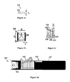
- FIG. 1a - 1i schematically illustrate detecting units 102 and detecting blocks 101 of various geometries and constructions, and radioactive-emission-measuring probes associated with them.
- Fig. 1a schematically illustrates a detecting unit 102, formed as a single-pixel detector 104, for example, a room-temperature solid-state CdZnTe (CZT) detector, having a diameter D and a thickness ⁇ d .
- CZT room-temperature solid-state CdZnTe
- Both the detector diameter D, or a diameter equivalent in the case of a non-circular detector, and the detector thickness ⁇ d affect the detecting efficiency.
- the detector diameter determines the surface area on which radioactive emission impinges; the greater the surface area, the greater the efficiency.
- the detector thickness affects the stopping power of the detector. High energy gamma rays may go through a thin detector, and the probability of their detection increases with detector thickness.
- a single-pixel detector cannot generate an image; rather, all counts are distributed over the surface area of the detector.
- Fig. 1b schematically illustrates the detecting unit 102 with a collimator 108, formed as a single cell of a diameter D, a length L, and a septa thickness ⁇ , attached to the detector 104.
- the collimator 108 may be, for example, of lead, tungsten or another material which substantially blocks gamma and beta rays.
- the collimator's geometry provides the detecting unit 102 with a collection angle ⁇ analogous to a viewing angle of an optical camera.
- the collection angle ⁇ limits the radioactive-emission detection to substantially only that radioactive emission, which impinges on the detector 104 after passing through a "corridor" of the collimator 108 (although in practice, some high-energy gamma rays may penetrate the collimator's walls).
- Fig. 1c schematically illustrates a block 101 of the detecting units 102, with the collimator 108, formed as a multi-cell collimator, of a cell diameter D.
- the collection angle ⁇ is defined for each of the detecting units 102 in the block, and each of the detecting units 102 forms a pixel in the block 101.
- Fig. 1d schematically illustrates a radioactive-emission-measuring probe 100 which comprises several detecting units 102, of different geometries and different collection angles ⁇ , within a housing 107.
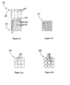
- Figs. 1e - 1i schematically illustrate the block 101, formed as a combination of a scintillation detector (such as NaI(Tl), LSO, GSO, CsI, CaF, or the like), a collimator grid, and photomultipliers.
- a scintillation detector such as NaI(Tl), LSO, GSO, CsI, CaF, or the like
- the block 101 having proximal and distal ends 109 and 111, respectively, vis a vis an operator (not shown), is formed of the scintillation detector 104, of a single pixel, and the collimators 108, to create the detecting units 102.
- a plurality of photomultipliers 103 is associated with the single pixel scintillation detector 104, and with proper algorithms, as known, their output can provide a two dimensional image of the scintillations in the single pixel scintillation detector 104. In essence, this is an Anger camera, as known.
- the distal view 111 of the collimator grid is seen in Fig. If.
- Figs. 1g and 1h Two optional proximal views 109 of the photomultipliers 103 are seen in Figs. 1g and 1h , as a square grid arrangement, and as an arrangement of tubes.
- An Anger camera 117, of the block 101 in the housing 107 is seen in Fig. 1i .
- the geometry of the collimator 108 determines the collection angle ⁇ , wherein with no collimator, the collection angle ⁇ , is essentially a solid angle of 4 ⁇ steradians.
- the collimator's geometry affects both the detection efficiency and the image resolution, which are defined as follows:
- the detection efficiency increases with increasing collimator's collection angle
- the image resolution decreases with increasing collimator's collection angle.
- the ratio of D/L is 1/2
- the collection angle ⁇ is substantially 2.5 steradians, so the cell views incident radiation within the confinement of about a 2.5-steradian sector.
- the ratio of D/L is 1/12
- the collection angle ⁇ is substantially 0.31 steradians, so the cell views incident radiation within the confinement of about a 0.31-steradian sector.
- the data is processed to reconstruct the intensity distribution within the measured volume.
- the reconstruction process is generally complex, due to the large quantity of data which must be processed in order to obtain an accurate reconstruction.
- the following statistical model may be used to perform reconstruction.
- I an intensity distribution, defined over an input space U , where U comprises a set of basic elements (e.g ., pixels in two dimensional spaces, voxels in three dimensional spaces), and I ( u ) is the intensity of a given basic element u ⁇ U.
- the geometrical and physical properties of the detecting unit, together with its position and orientation in a given measurement i determine the detection probability ⁇ i ( u ) of a photon emitted from location u .
- the effective intensity of location u as viewed by the detecting unit during measurement i is ⁇ i (u)I(u) .
- the random count X i ( u ) of photons that are emitted from location u and detected in measurement i is modeled by a Poisson process with mean ⁇ i ( u ) I ( u ).
- the reconstruction problem is to reconstruct the intensities I from the measurements y .
- the Radon transform is not statistical and does not take into account the Poissonian nature of the counts. In addition, it models the views as line projections.
- the Radon transform maps the spatial domain (x,y) to the Radon domain (p, ⁇ ). For a fixed projection angle, the Radon transform is simply a projection of the object.
- FBP filtered back-projection
- the basic, idealized problem solved by the FBP approach is to reconstruct an image from its Radon transform.
- the Radon transform when properly defined, has a well-defined inverse.
- In order to invert the transform one needs measured data spanning 180°.
- the positioning of the detecting unit relative to the emitting object is constrained, so that complete measured data is not available.
- Reconstruction based on filtered back-projection is therefore of limited use for medical imaging.
- Maximum likelihood (ML) and Maximum A Posteriori (MAP) estimation methods which address the statistical nature of the counts, have been found to provide better image reconstructions than FBP.
- Limited-angle tomography is a reconstruction technique in the related art which reconstructs an image from projections acquired over a limited range of angular directions. The success of the reconstruction process depends upon the extent of the angular range acquired compared with the angular range of the missing projections. Any reconstruction from a limited range of projections potentially results in spatial distortions (artifacts) in the image. Limited angle techniques can be applied for both the Radon transform and the statistical models, but better results are generally achieved within the statistical framework. While it is known that the severity of the artifacts increases with the increasing angular range of the missing projections, limited-angle tomography does not provide information on which projections should be used in order to most effectively reconstruct the image.
- Eqn. 2 For the maximum of the likelihood function.
- optimization methods that find local maxima of the likelihood are known.
- One such method is the Expectation-Maximization (EM) process.
- EM estimation there is no guarantee that the sequence converges to a maximum likelihood estimator. For multimodal distributions, this means that an EM algorithm will converge to a local maximum (or saddle point) of the observed data likelihood function, depending on starting values.
- a basic ingredient of the Expectation-Maximization formalism is to define a set of random variables that completely define the data generated by the model.
- the main tool in the EM formalism is the complete data likelihood: ln ⁇ P x
- I ln ⁇ t P x t
- I ⁇ t ln ⁇ u Poisson x t u
- ⁇ t u ⁇ I u ⁇ t ⁇ u - ⁇ t u ⁇ I u + x t u ⁇ ln ⁇ t u ⁇ I u + ln x t u !
- each EM iteration improves the likelihood.
- the EM algorithm iterates the above improvement step until it converges to a local maximum of the likelihood.
- Several random starts increase the chance of finding a globally good estimator.
- Limited computational resources may require breaking the update computation according to a partition of ⁇ into a set of sub-matrices ( ⁇ i ).
- y i is the vector of observations that are obtained using the views of ⁇ i .
- Singular value decomposition is a known technique for factorizing a rectangular real or complex matrix, with applications in signal processing and statistics.
- SVD may be considered a generalization of Eigenvalue decomposition to m*n matrices, whereas Eigenvalue decomposition is applicable only to square matrices.
- M UDV T
- D m-by-n with nonnegative numbers on the diagonal and zeros off the diagonal
- V T the conjugate transpose of V
- M is an n-by-n unitary matrix.
- the elements along the diagonal of D are denoted the singular values.
- Such a factorization is called a singular-value decomposition of M .
- a common convention is to order the singular values D i,i in non-increasing fashion, so that the diagonal matrix D is uniquely determined by M.
- condition number of a matrix is defined as the ratio of the matrix's largest singular value to its smallest singular value.
- condition number associated with a problem is a measure of that problem's amenability to digital computation.
- a problem with a low condition number is said to be well-conditioned, while a problem with a high condition number is said to be ill-conditioned.
- SVD may be employed for the solution of linear inverse problems.
- M UDV*
- y VD - 1 ⁇ U T ⁇ x
- U and V t are unitary matrices
- D is a diagonal matrix containing the singular values of M. Since U and V t are easily transposable, a solution to Eqn. 13 is obtainable only if D is invertible.
- Truncated SVD is a known technique for reducing sensitivity to inaccuracies or noise when solving a set of linear equations.
- the constraints associated with the smaller singular values are eliminated from the estimation.
- this is accomplished for the i-th singular value by setting e i -1 equal to zero in matrix D -1 .
- the lower valued singular values no longer affect the estimation process.
- a reliable, high-resolution image of the tested object i. e. body structure
- reliable reconstruction algorithms are available only for complete data sets, which provide coverage of the entire volume. Such data is generally not available during medical imaging.
- high-resolution detecting units when used, their efficiency is relatively low, and the detecting units must remain at each position for a relatively long time in order to achieve a high probability of detection. Since during medical testing, measurements are generally performed at many locations as the detecting unit is moved relative to the observed body structure, the testing procedure generally requires a long time and is physically and emotionally difficult for the patient.
- a reconstruction stabilizer for improving the reliability ofreconstruction of an imaged volume, as defined in appended claim 18.
- the present embodiments teach providing modifications of the reconstruction and/or imaging processes in order to obtain a reliable reconstruction of the imaged volume. Specifically, the methods teach analyzing the reliability of the reconstruction obtainable from collected emission data over a set of views to determine modifications which are expected to improve reliability. The present embodiments further teach using radioactive-emission measurements to define views for further radioactive-emission measurements of a body structure, to be performed during the current measurement process.
- the imaged volume corresponds to a body structure, which may include a whole body, portion of a body, target organ and so forth.
- a body structure which may include a whole body, portion of a body, target organ and so forth.
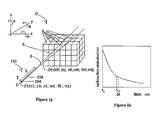
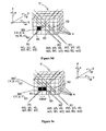
- Figs. 1j and 1k pictorially illustrate a view and viewing parameters associated with it, in accordance with definitions of the present invention.
- Seen in Fig. 1j is a volume U, subdivided into voxels u.
- the volume U is defined in a six-degree coordinate system (x;y;z; ⁇ ; ⁇ ; ⁇ ) and has a point of origin P0(x0; y0; z0; ⁇ 0; ⁇ 0; ⁇ 0).
- a detecting unit 102 is positioned at a location and orientation P1(x1; y1; z1; ⁇ 1; ⁇ 1; ⁇ 1).
- the detecting unit 102 has a detector 104 of a specific detector material of a thickness ⁇ d , and a collimator 108 of a diameter D and a length L, so as to define a collection angle ⁇ .
- the location, orientation, and collection angle parameters determine a three-dimensional sector S, which is the portion of the volume U that is within the detector unit's field of view.
- the probability of detection of a given voxel outside of sector S is negligible, since a photon emitted from the given voxel outside of sector S will have a very low probability of reaching detector 104 through collimator 108.
- Fig. 1k schematically illustrates the emission rate of the volume U, as a function of time, given that a radioactive material of a specific half-life has been administered at a time T0.
- a view may thus be defined as a group of nonzero probabilities of detecting a radioactive emission associated with all the voxels that form sector S ( Fig. 1j ).
- a view is sometimes referred to as a projection, and the two terms are synonymous.
- a view defined over the sector S can be naturally extended to be defined over the group of all voxels in the volume U, by simply associating a zero probability with every vovel outside the sector S. This enables applying mathematical operations over the entire volume U.
- the viewing parameters which are the factors affecting the detection of radioactive emissions, are as follows:
- Attenuation properties of all the voxels within the sector S as they affect the probabilities that radioactive emissions from a specific voxel within the sector S will reach the detector, wherein different voxels within the sector S may have different attenuation properties, since several types of tissue may be involved;
- the time t 1 since administration, and the duration of the measurement ⁇ t 1 affect the number of emissions that occur during the radioactive-emission measurement.
- the half-life t 1/2 , of the radiopharmaceutical, the types of radioactive emission, whether gamma or beta, and the energies of the radioactive emission affect the probability of detection.
- the tissue attenuation parameters are given. Additionally, the time t 1 since administration of the radiopharmaceutical is generally governed by the blood pool radioactivity, since it is generally necessary to wait until the blood pool radioactivity dies out for low-level detection to be possible. For the remaining viewing parameters, optimization may be carried out.
- volume U comprises a set of basic elements u (e.g., pixels in two dimensional spaces, voxels in three dimensional spaces), and I(u) is the intensity in a given basic element u ⁇ U.
- a view (also denoted a projection) ⁇ is defined by the set of probabilities ⁇ (u):u ⁇ U ⁇ , where ⁇ (u) is the probability of detecting a radioactive emission from a voxel u, as defined by viewing parameters, such as the physical and geometrical properties of the detecting unit, as well as the attenuation parameters of the viewed volume U, and the time parameters.
- a measurement is obtained by choosing a view ⁇ , and then sampling according to the viewing parameters.
- the reconstruction problem we are faced with is to calculate the intensity vector I from the measurement vector y , given a known probability matrix ⁇ .
- This model is suitable for least squares optimization when photon emissions have a Gaussian distribution, and thus may be reasonably applied when the measured counts (i.e. y) are relatively high.
- the embodiments are extendable to modeling the emissions as Poissonian.
- the y values of several low-intensity views are combined and set equal to the sum of all the related linear equations, in order to bring the total count into Gaussian range.
- I VD - 1 ⁇ U t ⁇ y
- condition number of D may serve as an indicator of the stability of the reconstruction, particularly during an iterative reconstruction process.
- known techniques such truncated SVD may be used for optimization and reconstruction purposes.
- the present embodiments are of a method, apparatus, and system which analyze the reliability of the reconstruction possible by a given imaging constellation, and define modifications in order to improve the quality of reconstruction.
- the modifications may be to the reconstruction and/or data collection aspects of the imaging process. As described below, the modifications may use active view selection during imaging and/or to guide non-uniform scanning of the imaged volume.
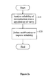
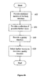
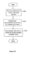
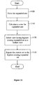
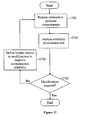
- Fig. 2a is a simplified flowchart of a method for stabilizing the reconstruction of an imaged volume, according to a preferred embodiment of the present invention.
- step 115 an analysis of the reliability of reconstruction of a radioactive-emission density distribution of the volume is performed. The analysis is made to determined the reliability of the data which may be collected by radioactive-emission measurements taken over a specified set of views.
- step 120 modifications to improve reliability of reconstruction are defined in accordance with the analysis. The modifications may involve a change or adaptation of the reconstruction process and/or a change or adaptation of the data collection process. Both the analysis and modification aspects of the present embodiment are described in detail below.
- the present embodiment tailors the reconstruction and/or data collections processes in order to obtain a more accurate reconstruction of the imaged volume.
- Low reliability data may cause large errors in the reconstruction process.
- the reconstruction process may be noisy and unstable, and fail to converge properly.
- the reconstructed image may contain artifacts, unsupported frequencies and other errors.
- the present embodiments are applicable to all stages of the imaging and/or reconstruction processes.
- the analysis may be performed prior to data collection, in order to define a scanning procedure which provides high-reliability data.
- the scan pattern may be adapted or views may be added (e.g. active vision/adaptive scanning), utilizing the new information provided by the collected data.
- modifications may be made to the reconstruction process in order to counteract the effects of unreliable data and non-uniformities, and to improve reconstruction accuracy and stability.
- the analysis of the reliability of reconstruction is based upon on analysis of the singular values of the probability matrix ⁇ .
- a non-limiting preferred embodiment of such an analysis is presented below.
- a detection probability matrix is provided.
- the detection probability matrix gives the detection probability for each of the views over the voxels of the volume. More explicitly, in the preferred embodiment each view has an associated row in the detection probability matrix. The values in a given row are derived from the probability of detection of a photon emerging from each of the voxels of the volume, by a detector at the associated view.
- the singular values of the detection probability matrix are calculated. In the preferred embodiment, the singular values are calculated by employing SVD on the detection probability matrix.
- step 135 those singular values which may have a destabilizing effect on the reconstruction process are identified as destabilizing singular values.
- a measure of the reconstruction reliability (denoted herein the reliability measure) is determined.
- the reliability measure is used for determining if any modification of the imaging and/or reconstruction processes is required, or if a stable reconstruction is possible without such modification.
- condition number of the probability matrix is utilized as a reliability measure. If the condition number is satisfactory the reconstruction may be considered stable, with no need for modification. Preferably, the identifying of destabilizing singular values is performed only if the condition number is below a specified magnitude.
- the information-theoretic Fisher information is calculated as a reliability measure from intensity distributions provided of the imaged volume.
- An intensity distribution may be obtained either as an emittance model created prior to the data measurement process, or as an intermediate result of the reconstruction process.
- the Fisher information is described in detail below, in the context of the reliability criterion for active vision.
- the identification of destabilizing singular values is performed as follows.
- the ratio of the largest singular value to each of the remaining singular values is calculated.
- a singular value for which the ratio is above a specified threshold is considered destabilizing.
- unreliable voxels or combinations of voxels associated with a given destabilizing singular value are identified.
- the intensity levels of such unreliable voxels or combination of voxels are unsupported in the collected emission data, due to the destabilizing effects of the associated singular value. Therefore the accurate reconstruction of such voxels and/or combinations is unlikely, and may destabilize the reconstruction process.
- the destabilization of the reconstruction by unsupported voxels may lead to artifacts and unsupported frequencies in the reconstructed intensities. These effects are not necessarily limited to the unsupported regions, but may extend into other portions of the volume and create artifacts there as well.
- the voxels and linear combinations of voxels associated with a singular may be determined via SVD decomposition of the intensity distribution matrix ⁇ .
- the matrix V obtained by SVD decomposition of ⁇ indicates voxels or linear combinations of voxels whose intensity after reconstruction is most highly affected by each of the singular values in D .
- Each row of V indicates a weighting associated with a given singular value for each voxel in I.
- e4 is a destabilizing singular value
- v 4 equals [0.001 0.01 0.97 0.015].
- the preferred embodiment is to perform smoothing of i3 relative to the neighboring voxels. Smoothing may be a practical approach where an inaccuracy occurs in spatially localized regions of the volume.
- An exemplary criterion to determine which voxels should be smoothed is to select voxels whose corresponding coefficient of v i is above a certain threshold.
- the unreliability of the data relates to a combination of voxels which may be distributed over the volume, rather than to an independent, spatially located voxel or group of voxels.
- the reliability of data regarding the linear combination 0.5i1-0.5i2+0.5i3-0.5i4, as reflected by measurements y, is low, which may lead to instability and inaccuracies during reconstruction. Since there are no dominant voxels it may be less effective to perform smoothing. Instead, the preferred embodiment is to constrain intensities of the combination of voxel intensities between iterations.
- constraints are added during the reconstruction process to reduce or eliminate the effects of the unreliable data associated with destabilizing singular values.
- the modifications include defining constraints on the reconstruction process.
- the reconstruction may be considered unreliable if one or more destabilizing singular values have been found, and the modifications may be made in order to reduce the effect of the destabilizing singular values upon the reconstruction. Examples of such constraints may include:
- Smoothing a reconstructed image is performed by calculating the intensity level of a voxel based on the intensities of surrounding voxels, in order to control the magnitude and rate of the fluctuations in intensities between voxels. For example, the intensity of a given voxel may be corrected to better reflect its value as an average of the surrounding voxels. Smoothing may be performed over the entire volume, or only on portions of the volume deemed unreliable.
- smoothing is performed directionally. In directional smoothing, the smoothing is weighted more strongly in certain directions than in others.
- directional smoothing is used to overcome the limitations of unreliable data by smoothing the voxel in the weaker directions.
- a higher resolution is available for some portions of the volume than is available in other portions. If it is important to obtain a reconstruction having a uniform resolution, directional smoothing may be applied reduce the resolution in highly reliable portions of the volume to the resolution obtainable elsewhere.
- a directional smoothing policy may be based on the Fisher information measure, which provides directionality information.
- the Fisher information matrix indicates directionality and cross-relationships between voxels, but may be difficult to calculate.
- a scalar Fisher information is calculated for groups of views, where each group is localized in a given direction. The scalar Fisher information measures may then be analyzed together, in order to determine the relationships between the different directions.
- Low reliability voxels may be united or combined with surrounding voxels in order to increase their reliability.
- Voxels may combined by assigning the intensity level of a neighboring high-reliability voxel to the low-reliability volel.
- Voxel merging may be carried out more extensively, by repeatedly merging the lowest reliability voxel with one of the neighboring voxels to form an aggregate of voxels, until no voxel is left with a reliability below a threshold. It will be appreciated that the aggregate voxels have a lower resolution locally, but all other regions with good coverage remain of high resolution, according to their coverage.
- An opposite approach for high-reliability portions of the volume is to subdivide high-reliability voxels into smaller voxels in order to improve resolution while still achieving a required reliability. For example, if there are 1000 different views independently covering 1 cubic cm and almost not affected by the surrounding voxels, then theoretically that volume can be divided up to about 1000 voxels, if the views create a linearly independent set of equations with a good condition number.
- a further possible modification of the reconstruction process may be to adjust the effect of certain unreliable voxels or linear combinations of voxels after each of one or more iterations of the reconstruction process.
- the magnitude of unreliable voxels or combinations of voxels associated with a destabilizing singular value may be reduced towards zero or towards the value of neighboring voxels by a specified factor, possibly in proportion to their respective weightings in the associated row of matrix V and/or to the associated singular value.
- a realistic range of counts may be defined overall or per view based on view parameters, typical spatial structures and the like. Examples include adding a prior constraint such as a gamma distribution of intensities, a constant or piecewise-constant progression of intensities, a linear or piecewise-linear progression of intensities, smoothing or piecewise smoothing constraints, an intensity distribution based on the shape of or magnitude of the object being scanned (possibly determined during a pre-scan), or a maximal or known range of expected intensities,
- the reconstruction process may be performed in a manner that obtains varying resolutions over the volume.
- the entire volume is defined as a single huge voxel, and split over the reconstruction iterations to form smaller voxels.
- the process is performed repeatedly over all or some of the voxels of the volume, as long as the result of the split maintains a reconstruction reliability high enough for stable results.
- the information-theoretic Fisher information is used as a reliability measure. Modifications to the reconstruction and/or data collection processes may be performed when the Fisher information is deemed to be outside a specified range.
- the calculation of the Fisher information is described in detail below, in the context of the reliability criterion for active vision.
- the Fisher information may be calculated from the results of a previous reconstruction iteration, or, initially, from an emittance model provided of the imaged volume.
- the following addresses a preferred embodiment in which the modification is implemented by defining views for imaging the volume.
- the defined views serve to guide the data collection process in order to obtain measurements which enable performing a stable and accurate reconstruction of the intensity distribution of the volume.
- detecting resources may be invested effectively in order to improve reconstruction reliability.
- Scanning resources include, for example, detector dwell time, number of detectors, angular and translational increments, and the like-features that increase the amount of data collection.
- Such modification may be performed when a region is interesting but is still left with coarse resolution, so as to allocate more scanning resources, such as dwell time, number of detectors, angular and translational increments, to cover that region and to form more independent views such as to increase the reliability of the reconstruction of that area.
- the views are defined so as to obtained a desired resolution over the region of interest.
- a scanning density may be specified by the angular and translational increment size, or steps, the smaller the increment, the higher the density. Additionally, the scanning density may be defined by the acquisition time at each position - the longer the time, the higher the density.
- Non-uniform scanning may be defined by specifying varying scan densities for imaging the volume.
- the modification may entail adjusting a local scanning density to scan a region of interest with high density, and to scan other regions with low density.
- the non-uniform scans may relate to non-uniform angular steps of the detector along a sweep, non-uniform detector translational steps, or different steps by different detectors. Some detectors may employ dense steps and others may employ sparse steps, for example, based on active vision as taught hereinbelow.
- the scan density may be adapted to the distance to the object of interest. Since resolution decreases with distance, the higher density may compensate for increased distance.
- the angular steps may increase in density when scanning a region of interest, and decrease in density, when scanning other portions of the volume.
- the two regions of interest may be, for example, a tissue region and a blood pool region. This has applicability, for example, to dynamic studies of blood perfusion, by providing even scanning resources both to the blood and to the tissue.
- convex scans may be employed.
- Variable scans where a same region is scanned first with a first density and then with another density, may be employed.
- a same region may be scanned by a first group of detectors with a first density and then by a second group of detectors with another density, concurrently, or at different times.
- the same region is scanned with at some density by a given detector and at a different density by another detector.
- view definition is performed dynamically during radioactive-emission measurements of the volume.
- the definition of further views for measurement during the data collection process is denoted active vision herein and is described in detail below. Active vision may be performed independently or in conjunction with the present preferred embodiment of stabilizing the reconstruction of an imaged volume.
- the method includes the further step of iteratively reconstructing the radioactive-emission density distribution of the volume, preferably by EM estimation. Reconstruction reliability is preferably evaluated after every iteration.
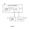
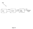
- Reconstruction stabilizer 140 includes reliability analyzer 145 which analyses the reconstruction reliability of a radioactive-emission density distribution of a volume.
- the reconstruction reliability may be determined from measures such as the condition number of the probability density matrix or the Fisher information, as described above.
- Modifier 150 defines modifications to improve the reliability of the reconstruction, based on the analysis performed by reliability analyzer 145.
- Modifier 150 preferably applies at least one constraint to the reconstruction process and/or data collection.
- the constraints may include applying smoothing, uniting voxels, adjusting the levels of voxels, defining new views or non-uniform scanning, and other constraints described above.
- the views may be defined before or during emission data collection.
- reconstruction stabilizer 140 is included in a system for generating a three-dimensional image of volume.
- the system further includes radiological imaging camera 155 and reconstructor 160.
- Camera 155 includes detectors capable of independent movement during data acquisition, and which are capable of detecting radiation emitted from the volume thereby to provide radiation data.
- each block of the imaging camera construction or each detecting unit, where single-pixel detecting units are used may be provided with at least one, and preferably, two, three, or as many as six degrees of motion such as, for example, rotational motion around the x, y, and z, axis, oscillatory motion about these axes, or translational motion along these axes.
- Camera 155 thus enables flexible view definition by modifier 150, increasing the likelihood that a reliable reconstruction will be achieved.
- Reconstructor 160 analyzes the radiation data provided by camera 155 so as to reconstruct a three-dimensional image of the volume.
- Reconstructor stabilizer 140 guides camera 155 and reconstructor 160, by providing one or both with the modifications determined to improve reconstruction reliability.
- calculations are performed in a localized manner. That is, calculations are performed for different sections of the volume in turn, progressing through the volume until it is covered in its entirety.
- the variables relating to the other sections are "frozen". Thus first a selected section of the volume may be stabilized, so that the reconstruction of following sections is based on data with improved reliability.
- Localized calculations such as SVD decomposition, are performed on smaller sub-matrices rather than on a single large matrix, alleviating the difficulties of manipulating very large matrices.
- the division of the volume into sections may be devised in any practical way, for example as sequential slices or by another spatial connection.
- the division may be based on the scan pattern, so that well-supported sections may be stabilized first, followed by less supported section.
- the division may also or alternately be based on knowledge of the body being imaged, such as its shape or composition.
- the sections When imaging a body structure, the sections may be based on the known axes or structures of the organ
- the following embodiments are of a method for determining further views for the imaging of a body structure, denoted active vision herein.
- Active vision addresses the problem of ensuring that the quality of data gathered during the measurement process is adequate to provide a high quality image.
- the collected data and/or the image reconstructed from the collected data is analyzed the while the measurement process is taking place. Based on the analysis, further views are defined. Since each view is associated with known values of the viewing parameter(s), selecting a view effectively specifies known viewing parameter values.
- the defined further views thus define a set of viewing parameter values, which are used during the current measurement process in order to collect data which yields a high-quality reconstruction of the body structure.
- Active vision may be performed independently, as described in the embodiments presented below. Additionally or alternatively, active vision may be performed in conjunction with the above-described method for stabilizing reconstruction, by modifying data collection by dynamically providing additional views to improve reconstruction reliability (see Fig. 17 ).
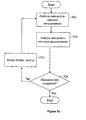
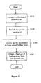
- Fig. 2d is a simplified flowchart of a method of performing radioactive-emission measurements of a body structure, according to a preferred embodiment of the present invention.
- radioactive-emission measurements of the body structure are performed at predetermined views, preferably in vivo. Preferably the measurements are performed for diagnostic purposes. These predetermined views are selected prior to the measurement process, based on a model of the body structure being imaged. In the model more and less informative viewing directions have been identified.
- the predetermined views of step 200 preferably include those views expected to be informative, based on an analysis of the model.
- the body structure is all or a portion of: a prostate, a heart, a brain, a breast, a uterus, an ovary, a liver, a kidney, a stomach, a colon, a small intestine, an oral cavity, a throat, a gland, a lymph node, the skin, another body organ, a limb, a bone, another part of the body, and a whole body.
- step 210 the radioactive-emission measurements are analyzed.
- the analysis includes one or more of:
- step 220 further views for measurements are dynamically defined, based on the analysis performed in step 210.
- each of the views is associated with viewing parameters selected from the group consisting of: detector unit location, detector unit orientation, collection angle, and measurement duration.
- Defining a view consists of providing a value for each of the parameters associated with the given view.
- the analysis (step 210) and/or dynamic view definition (step 220) may take into account external parameters including: measurement duration, time elapsed from the administration of the pharmaceutical to the measurement, radiopharmaceutical half life, radioactive emission type, and radioactive emission energy.
- a photon count analysis ensures that the photon count at a given view yields an acceptable measurement error.
- the radiative emissions of the body structure being imaged is a Poisson process.
- the Poisson noise grows inversely to the square root of the number of photons detected. In other words, if N photons are collected from a given view, the resulting signal to noise ratio (SNR) equals:
- the unprocessed detector photon count at a given view thus provides significant information regarding the quality of the information obtained at a given view. If the photon count is too low, it may be desired to continue to collect photons at the current location/orientation in order to obtain a satisfactory SNR. Alternatively, it may be determined that enough photons have already been collected, and to terminate the current view and move on to the next view.
- the analysis is preferably performed by defining a global or local required measurement error, and comparing the square root of the obtained photon count to the required measurement error.
- Photon count analysis can be applied to the current and/or previous views. When a photon count of a current view is found to be too low, the duration of the current view is preferably extended in order to obtain the required error value. When a photon count of a past view is found to be too low, an emission measurement at substantially the same location and orientation but having a longer duration than previously is preferably performed. Alternately or additionally, the collection angle at the given location/orientation is preferably increased.
- a detector photon count is analyzed to identify detector saturation at a given view.
- a new view or views are selected to reinforce those views that have saturated.
- further views are defined to avoid highly-radiating portions of the body structure.
- a photon collection rate at a given view is analyzed to determine if it is within a specified range.
- the photon count rate is used to identify regions of high or low interest.
- a region of high interest may be identified by a high photon rate, indicative of a tumor.
- a region of high interest may be identified in heart imaging by a low photon rate, indicative of non-functional tissues.
- further views are preferably defined by selecting views to concentrate on regions of high interest and/or to avoid regions of low interest. It is thus possible to zoom in on a suspected pathology without repeating the emission measurement process.
- the analyzing of step 210 includes reconstructing a radioactive-emission density distribution of the body structure. Reconstruction may be performed according to any applicable technique known in the art. The reconstruction is then used as the basis for further analysis.
- Reconstruction based on the data collected from the predetermined views provides information regarding the quality of information obtained from the preceding measurements, and which further views are likely to be most informative. Selecting new views based on reconstruction is intended to bring us into viewing from the more informative views or combinations of views.
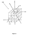
- FIG. 3 shows an object 300 shaped as a cylinder with a front protrusion, and having a high-emittance portion (hotspot) 310.
- Four views of object 300 are shown, which can be seen to provide different levels of information.
- Front views, such as V 1 provide little information regarding the shape of object 300 and have relatively little attenuation between the detector and hotspot 310.
- Side views, such as V 2 provide edge information regarding the object shape or profile, and when correlated with front views help locate hotspot 310 spatially within object 300.
- Top views, such as V 3 provide information, regarding the cylinder edge region 320.
- rear views, such as V 4 are uninformative about the shape of object 300 and have high attenuation relative to hot region 310.
- Figs. 4a and 4b demonstrate how the proper selection of views may improve the quality of information obtained for the body structure, for example in distinguishing between two regions of interest within a given volume.
- Fig. 4a illustrates an object 400 having two high-emission regions of interest (ROI), 410 and 420.
- ROI regions of interest
- V A to V F are shown as lines in Fig. 4a , however in practice they will each have a finite collection angle ⁇ .
- the position of ROIs 410 and 420 are assumed to have been estimated based on a model of object 400 and/or a previously performed prescan.
- the goal of the present invention is to select an additional new view or views which increase the information we have regarding the separation of ROIs 410 and 420 within object 400.
- ROI 410 with intensity I 1 ROI 410 with intensity I 1
- ROI 420 with intensity I 2 ROI 420 with intensity I 2
- a low-emission region 430 between the two ROIs with intensity I 3 The detected intensity at a given detector is proportional to / r ni 2 I n , where I n is the emission intensity of region n and r i is the distance of region n from detector V i .
- Fig. 4b illustrates the added information provided by each of the shown views, V A to V F .
- Views V B and V C collect emissions from all three regions, and are therefore least informative.
- Views V D and V E collect emissions from only low emittance region 430, and therefore provide most information regarding the location of each ROI within the volume and the separation between ROIs 410 and 420.
- Views V A and V F pass only through a single ROI, and therefore provide an intermediate level of information. It is a goal of the present invention to determine, while the emission measurements of the body structure are taking place, that views in the vicinity of V D and V E are highly informative, and to add these further views to the measurement process.
- a body structure reconstruction can be utilized in several ways to define further views.
- a first way is to identify interesting portions of the contour and structure of the reconstruction. For example, it is seen in Fig. 3 that top views are infonnative about edge region 320. Further top view measurements will therefore be informative re edge region 320, and may enable defining the edge more accurately.
- the reconstruction is analyzed to identify textural edges within the reconstruction, and view definition preferably includes selecting views at an angle to the textural edges.
- the angle is a substantially sharp angle in order to provide information regarding the edge.
- the reconstruction is analyzed to identify volumetric boundaries within the reconstruction, and view definition preferably includes selecting views at an angle to the volumetric boundaries. It is expected that the defined views will provide information regarding the boundary and differences in surrounding tissues on either side of the boundary.
- the angle is a substantially sharp angle.
- Another way to utilize the reconstruction to define further views is to identify suspected organ targets within the reconstruction, and to select further view(s) in close proximity to the suspected organ targets.
- a suspected organ target is typically detected by identifying portions of the reconstruction whose emission intensity distribution and spatial characteristics are typical of a suspect region.
- a suspected organ target is defined as a high-emittance portion of the reconstruction.
- a suspected organ target may be a high-emittance portion of the structure, indicating a tumor.
- a high-emittance portion is characterized by an intensity that is greater than the background intensity by a factor of at least (1+ ⁇ ), where ⁇ is a parameter specified by the user.
- ⁇ is a parameter specified by the user.
- a hotspot is usually detectable only if the radiation levels within the hotspot are higher than the background level by a factor of 1.5-2. ⁇ is therefore typically defined between 0.5-1. However, the detectability of a hotspot rises as the radioactive intensity of the body rises, raising the photon count.
- a lower value of ⁇ may be used when the measured body structure is in a state of high-intensity emittance.
- a body structure may be characterized by relatively high emittance immediately following the administration of the radiopharmaceutical, and be characterized by lower emittance at a later time.
- a suspected organ target is defined as a low-emittance portion of the reconstruction.
- a suspected organ target is defined as a low-emittance portion of the reconstruction, indicating non-functional tissues.
- a low-emittance portion is characterized by an intensity that is lower than the background intensity by a factor of at least (1+ ⁇ ), where ⁇ is a parameter specified by the user.
- the further views are used immediately for radioactive-emission measurements.
- the results of the new measurements are then used in another analysis to define new further views for additional measurements.
- the radioactive-emission measurements may then be said to be performed iteratively.
- Fig. 5a is a simplified flowchart of a iterative method of performing radioactive-emission measurements of a body structure, according to a first preferred embodiment of the present invention.
- step 500 radioactive-emission measurements of the body structure are performed at predetermined views.
- step 510 an analysis is performed of the previously performed emission measurements.
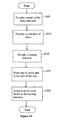
- step 520 a decision is made whether to continue with further measurements. If yes, in step 530 further views are defined based on the analysis. Subsequent iterations continue until the decision to end the emission measurement process.
- the analysis performed at a given stage may include consideration of all or on part of the measurements performed during one or more previous iterations, in addition to the new measurements.
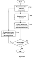
- Fig. 5b is a simplified flowchart of a iterative method of performing radioactive-emission measurements of a body structure, according to a second preferred embodiment of the present invention.
- a reconstruction of the body structure is formed in step 505.
- the analysis step 510 is then performed utilizing data provided by the reconstruction(s).
- analysis step 210 includes determining an accuracy of the reconstruction.
- Accuracy is preferably determined by analyzing the variance of the reconstructions formed over multiple iterations.
- further views are defined in step 220 to concentrate on the region for which higher accuracy is required. Regions of the reconstruction having low variance provide a high degree of confidence regarding the accuracy of the reconstruction in the given region (where a portion may include the entirety of the body structure being imaged). Further views may be added to the current measurements until the variance is reduced to a required level.
- analysis step 210 includes determining a resolution of the reconstruction.
- Resolution is preferably determined by analyzing the full width at half maximum (FWHM) of peak values of the reconstruction.
- the FWHM is given by the distance between points at which the reconstructions reaches half of a peak value.
- further views are defined in step 220 to concentrate on the region for which higher resolution is required.
- An additional way to define future views using the reconstruction is on an information-theoretic basis.
- a quality function expressing an information theoretic measure is defined.
- the quality function rates the information that is obtainable from the body structure when one or more permissible views are added to current measurement process.
- quality functions based on information-theoretic measures are discussed in detail below.
- the quality function is used to rate potential further views. The measurement process may then continue at those further views whose addition to the previous views yields a high rating.
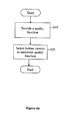
- Fig. 6a is a simplified flowchart of a method for dynamically defining further views, according to a first preferred embodiment of the present invention.
- the quality function expresses an information-theoretic measure which rates the quality of information obtainable from potential further views.
- a set of further views is selected to maximize the quality function.
- the selected further views fulfill certain constraints; for example the further views may be selected from a predefined set or may be located in the vicinity of a region of interest within the body structure.
- an emittance model is a representation of a specific radioactive-emission intensity distribution within the volume U, so as to model organ targets, such as hot regions, of a radioactive emission intensity, higher than the background level, regions of low-level radioactive emission intensity, which is nonetheless above the background level, and cold regions, of a radioactive emission intensity, lower than the background level.
- emittance models may be devised to reflect expected or typical emission patterns for the given object.
- Developing an emittance model for a particular body structure involves analyzing known information about the body structure to determine expected emission patterns of the body structure.
- a model of a particular body structure for example a prostate
- many factors may be considered. Physical aspects, such as the size and shape of the prostate and the position of the prostate within the torso may be considered, as well as medical knowledge regarding typical emissions from healthy and diseased prostates. Additional information may concern variations between individuals, such as age, weight, percentage of body fat, and the like.
- the following discussion describes the evaluation of information-theoretic quality functions based on emittance models only. It is to be understood that at least one of the emittance models is a reconstruction of the body structure based on past measurements. Any remaining emittance models are provided externally, and may be based on general medical knowledge or on information gathered during a previous round of emission measurements of the body structure.
- Fig. 6b is a simplified flowchart of a method for dynamically defining further views, according to a second preferred embodiment of the present invention.
- the current method differs from the method of Fig. 6a by the addition of steps 605-606.
- step 605 a set of one or more emittance models is provided (where the set includes one or more reconstructions of the body structure).
- An emittance model specifies the radiative intensity of each voxel in the body structure.
- some of the viewing parameters affect the radiative intensity of the voxels in the volume, for example the type of radiophannaceutical and the time since administration of the radiopharmaceutical. Therefore, the enuttance models provided in step 605 preferably correspond to the relevant viewing parameters.
- step 606 a collection of possible further views of the body structure is provided. The collection of views includes possible further views for future measurements, preferably based on anatomical and other constraints.
- the quality function provided in step 610 may utilize multiple emission models.
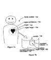
- FIG. 7a schematically illustrates a body section 720, having a region of interest (ROI) 730.
- the region of interest 730 is associated with a body structure 740, with a specific radioactive-emission-density distribution, possibly suggestive of a pathological feature 750, termed herein an organ target 750. Additionally, there may be certain physical viewing constraints, associated with the region of interest 730.
- Model 760 as illustrated in Fig. 7b , represents body section 720 as a collection of voxels, having a specified radioactive-emission intensity distribution.
- the model 760 of the region of interest 730 may be based on general medical information of the body structure 740 and common pathological features associated with it. Additionally, the model may be based on information related to a specific patient, such as age, sex, weight, and body type. Furthermore, a structural image, such as by ultrasound or MRI, may be used for providing information about the size and location of the body structure 740 in relation to the body section 720, for generating the model 760.
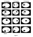
- Fig. 8 shows four models of a prostate emittance model.
- Three views are given for each of the emittance models shown.
- Each of the views is a maximum intensity projection (MIP) along a different one of the three axes.
- MIP maximum intensity projection
- X-Y projection the intensity of a given point is taken as the maximum intensity for that point along a line parallel to the z-axis.
- the volume in effect becomes “transparent”, and the maximum intensity regions are shown clearly.
- Variations in emission levels are indicated by differences in shading.
- the emittance model is shaped as an ellipsoid, the typical shape of a prostate.
- each of the emittance models shown has a number of high-emittance portions (two hot regions in Models A-C and three hot regions in Model D).
- Each high-emittance area is an ellipsoid, with a size of approximately 1 cubic centimeter.
- the intensity of the modeled organ targets varies randomly from two to eight times brighter than the surrounding volume.
- one or more of the emittance models contains at least one high-emittance portion (i.e. hot region).
- a prostate containing a tumor for example, may be modeled as an ellipsoid volume with one or more high-emittance portions.
- one or more of the emittance models contains at least one low-emittance portion.
- a diseased heart may therefore be modeled as a heart-shaped volume with low-emittance portions.
- an emittance model need not contain high- or low- emittance portions, but may have a uniform intensity or a slowly varying intensity.
- quality functions both of which include considerations of the emission distribution of the volume, in light of the emittance models provided (step 605 of Fig. 6b ).
- the information quality given by one or more further views is evaluated in relation to multiple reconstructions and/or emittance models of the body structure.
- the quality function is based on an information theoretic measure of separability.
- the quality function is based on an information-theoretic Fisher information measure, for ensuring reliable reconstruction of a radioactive-emission density distribution.
- the quality function implements a separability criterion.
- Separability is a measure of the extent to which the measurements that are obtained from each pair of models can be distinguished from one another.
- Figs. 9a-9c each of which shows an emittance model of a given volume 900.
- Each of the emittance models contains two high-emittance portions (hot regions), 910 and 920, which are located in respectively different locations in each of the models. It can be seen that the hot regions in emittance models 9b and 9c are in similar positions of the volume, as opposed to the hot regions in model 9a. It may therefore be difficult to distinguish between reconstructions of emittance models 9b and 9c.
- the separability criterion ensures that the selected set includes views which provide reconstructions which distinguish between emittance models 9b and 9c.
- I be the emittance model set
- a measure for the dissimilarity of any two given densities in I is defined. Since most state-of-the-art estimating algorithm are aimed at finding ML estimators, in the current example the quality function is based on the likelihood function.
- Equation 20 The expectations and variances in Equation 20 are taken over random measurements y, sampled from the true intensity I 1 (note that the measure is not symmetric).
- ⁇ * arg max ⁇ ⁇ min I 1 , I 2 ⁇ I SEPARABILITY ⁇ I 1 I 2
- Scoring for separability is based on the minimum separability obtained with a given set of views for all of the possible pairings of emittance models from the set of emittance models, thereby enabling defining a desired resolution in more than one direction, or in more than one portion of the volume.
- All of the emittance models are modeled on a substantially identical volume.
- the emittance models preferably differ from one another in the modeled organ targets, where the modeled organ targets are separated by a difference of at least the required resolution (where the displacement which produces the required resolution is denoted delta herein).
- Substantially identical sets of views are formed from the collection of views, and each of the formed sets is scored with respect to each of the pairs. One of the sets of views is selected, based on the minimum or average score for the plurality of pairs.
- the set of emittance models contains the three models 9a-9c.
- a separability score is calculated for a given formed set of views by applying Equation 20 to all three pairs 9a/9b, 9a/9c, and 9b/9c. The lowest of the three calculated values is taken as the separability score for the formed set. Once a separability score has been calculated in such manner for each of the formed sets of views, the view set having the highest separability is selected.
- the separability criterion may be used to ensure that a required resolution is obtained in all or a portion of the body.
- view set selection for separability is performed utilizing a set of emittance models consisting of one pair of emittance models having substantially identical volumes but with different modeled organ targets.
- the modeled organ targets are separated by a delta in a given direction so as to define a required resolution in that direction and portion of the volume U.
- Substantially identical sets of views are formed from the collection of views, and scored with respect to the pair of emittance models, using a quality function based on the separability criterion, and one of the sets of views is selected based on the separability scores.
- the selected set is thus the set which provides the optimum resolution in the given direction and in the vicinity of the modeled organ targets.
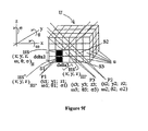
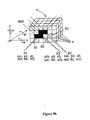
- FIG. 9d which schematically illustrates the volume U, having the modeled organ target HS, whose center is at a location (x;y;z) HS
- Fig. 9e which schematically illustrates the volume U, having the modeled organ target HS', whose center is at a location (x;y;z) HS'
- Fig. 9e also shows modeled organ target HS of Fig. 9d superimposed over the present emittance model to illustrate that HS' is somewhat displaced from HS, along the x-axis, and the displacement, is denoted as delta1 in the present example.
- the displacement delta may be measured, for example, in mm.
- a score, in terms of separability is given for the pair of models, and relates to a resolution as defined by the difference between the models of the pair.
- the difference is delta1 along the x-axis, around the locations of HS and HS', so the score given by the information theoretic measure of separability will relate specifically to a resolution as defined by deltal along the x-axis, around the locations of HS and HS'.
- Other portions of the volume U and other directions may have different resolutions.
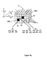
- Fig. 9f schematically illustrates the volume U, having the modeled organ target HS", whose center is at a location (x;y;z) HS ", and shows HS of Fig. 9d and HS' of Fig. 9e superimposed over the present emittance model.
- HS is displaced from HS, along the z-axis, a displacement delta2.
- HS is displaced from HS', along the x- and z- axes, a displacement delta3.
- Scores in terms of separability, may be given to all the paring combinations, that is the models of Figs. 9d - 9e , relating to delta1; the models of Figs. 9d -9f , relating to delta2, and the models of Figs. 9e - 9f , relating to delta3.
- An optimal set of views may be selected based on its minimum or average scores for all the pairing combinations; for example, the optimal set of views may be that whose average score for all the pairing combinations is the highest. Alternatively, a weighted average may be applied.
- the quality function implements a reliability criterion, which is a measure of how reliably the intensity distribution of a given object may be reconstructed from the sampled views. Since the input to the reconstructed algorithm is a random sample, the output estimator is also random. A desired property of this output is that it be reliable in the sense that similar estimators for different projected samples (i.e. different sets of measurements) of the same input intensity are obtained with high confidence.
- the Fisher Information, F ⁇ ( I ) is a measure, known in the art, which is used to evaluate the expected curvature of the likelihood of a model I (taken over measurements sampled from the model I ).
- the Fisher information provides a value, F ⁇ ( I ) u,y , for each pair of voxels u and v .
- the average level, worst case, or other reasonable measure may be taken over the voxels.
- the quality function is based on the average Fisher information.
- Equation 24 Since inverting F ⁇ ( I ) may be computationally expensive, the ⁇ F ⁇ ( I ) -1 ⁇ u,u term in Equation 24 may be replaced with 1/[ F ⁇ ( I )] u,u (thus neglecting the off-diagonal elements of the Fisher Information matrix F ⁇ ( I )). Note that Equations 23 and 24 are not mathematically equivalent, and may therefore yield different selected sets.
- evaluating the quality function is performed using the reliability criterion, and two or more emittance models are provided, having substantially identical volumes, but different modeled organ targets. Substantially identical sets of views are formed for all the emittance models, and each set is scored for reliability. One of the sets of views is then selected based on the average score for all the of the emittance models.
- a weighted combination of several information theoretic measures is used.
- a plurality of models may be provided, all having substantially identical dimensions and volumes, as follows:
- Identical sets of views may be applied to all the models, and each view may be scored in terms of separability and reliability.
- An optimal set of views may be selected based on a summation of the two scores, or based on a weighted average of the two scores, where the relative weight given to each criterion reflects the relative importance of each measure per the given application.
- the quality function is preferably defined in accordance with one of the following: worst case effectiveness for the given further view over the volume, average effectiveness for the given further view over the volume, worst case effectiveness for the given further view over the set of emittance models and average effectiveness for the given further view over the set of emittance models.
- Maximization of the quality function may be performed utilizing any method known in the art such as simulated annealing and gradient ascent.
- SA simulated annealing
- each point of the search space is compared to a state of some physical system.
- the quality function to be maximized is interpreted as the internal energy of the system in that state. Therefore the goal is to bring the system from an arbitrary initial state to a state with the minimum possible energy.
- the neighbors of each state and the probabilities of making a transition from each step to its neighboring states are specified.
- the SA heuristic probabilistically decides between moving the system to a neighboring state s' or staying put in state s.
- the probabilities are chosen so that the system ultimately tends to move to states of lower energy. Typically this step is repeated until the system reaches and acceptable energy level.
- the set of views selected with the quality function is increased by at least one randomly selected view.
- the randomly selected view(s) increase the probability that the quality of information obtained with the further views is maximized globally rather than locally.
- selecting the best set of size N from amongst a large set of candidate projections is computationally complex. Since the size of the collection of views and of the required set may be large, a brute force scheme might not be computationally feasible.
- a so-called “greedy algorithm” is used to incrementally construct larger and larger sets, until the required number of further views is defined.
- the greedy algorithm reduces the computational burden by selecting the further views one at a time. The algorithm starts with a current set of views, and for each iteration determines a single view that yields the maximum improvement of the set score (hence the name "greedy").
- a respective score is calculated for a combination of the previous set with each of the views which is not a member of the current set.
- the current set is then expanded by adding the view which yielded the highest respective score, and the expanded current set serves as the input to the following iteration.
- Fig. 10 is a simplified flowchart of an iterative "greedy" method for defining further views, according to a preferred embodiment of the present invention.
- a collection of views of the body structure is provided.
- the collection of views includes possible further views for future measurements, preferably based on anatomical and other constraints.
- the set of views used for the previous emission measurements is established as a current set of views.
- the view set is incrementally increased by a single further view during each iteration, until the required number of further views has been selected.
- Fig. 11 is a simplified flowchart of a single iteration of the view selection method of Fig. 10 , according to a preferred embodiment of the present invention.
- the method of Fig. 11 expands the current set of views by a single view.
- the method begins with a current set of views, which is the predetermined set (step 1010 above) for the first iteration of the greedy algorithm, or the set formed at the end of the previous iteration (step 1120 below) for all subsequent iterations.
- a respective expanded set is formed for each view not yet in the current set of views.
- a given view's expanded set contains all the views of the current set of views as well as the given view.
- step 1110 a respective score is calculated for each of the expanded sets using the quality function.
- step 1120 the view which yielded the highest-scoring expanded set is selected as a further view, to be used for further radioactive emission measurements.
- step 1130 the current set is equated to the highest-scoring expanded set by adding the selected view to the current set. The newly formed current set serves as an input to the subsequent iteration, until the desired number of views is attained.
- Fig. 12 is a simplified flowchart of a method for dynamically defining further views,, according to a third preferred embodiment of the present invention.
- step 1210 a collection of possible further views for performing radioactive-emission measurements of the body structure is provided.
- Each of the views is associated with at least one viewing parameter.
- the viewing parameters consist of at least one the following: detector unit location, detector unit orientation, collection angle, and measurement duration.
- step 1220 at least one quality function is provided.
- Each quality function is for evaluating sets of views, essentially as described above.
- a single quality function may be used to select several sets of views, where each set of views contains a different number of views.
- step 1230 multiple sets of further views (where a set may include a single further view) are formed from the collection of views, using the quality function(s) provided in step 1220.
- each of the sets is formed using a different one of the quality functions.
- one or more of the quality functions are used to form more than one set of views, where sets formed with the same quality function have differing numbers of views.
- step 1240 a selected set of views is obtained from the sets formed in step 1230.
- the final set of views is obtained by choosing one of the sets formed in step 1230 using a set selection criterion. For example, a respective set is formed in step 1230 for the separability and reliability criteria independently.
- a set selection criterion which calculates an overall performance rating for a given set taking both criteria into account is defined, and the formed set with the highest overall rating is selected as the final set.
- the selected set of views is obtained by merging the sets formed in step 1230 according to the relative importance of the respective quality function used to form each set.
- the method further consists of providing at least one emittance model and/or reconstruction representing the radioactive-emission density distribution of the volume, and of evaluating with at least one of the quality functions of step 1220 is performed in relation to the emittance models.
- the selected set yields a group of parameter values for performing effective detection of the intensity distribution of the body structure. For example, if each view is associated with a view location parameter the selected set defines a set of locations for collecting emission data from an object, in order to provide a high-quality reconstruction of the intensity distribution of the body structure.
- Measurement unit 1300 includes probe 1310, analyzer 1320 and view definer 1330.
- Probe 1310 performs the radioactive-emission measurements of the body structure.
- Radioactive-emission-measuring probe 1310 preferably comprises several detecting units, which may be of different geometries and different collection angles ⁇ , within a housing (see for example Fig. 1d ).
- the orientation and/or collection angle of the individual collimators is controllable.
- Analyzer 1320 analyzes the radioactive-emission measurements obtained from probe 1310.
- View definer 1330 dynamically defines further views for measurements, based on the analysis provided by analysis unit 1320. The analysis and view definition are performed substantially as described above.
- the abovedescribed methods for radioactive-emission measurements of a body structure begin by performing measurements at a predetermined set of views. The results of the initial measurements are then analyzed and further views are defined.
- the initial set of views is preferably selected based on information theoretic measures that quantify the quality of the data fed to the reconstruction algorithm, in order to obtain the best data for reconstructing a three-dimensional image of the body structure.
- the following section concentrates on the second step of the process, namely, obtaining the optimal and permissible set of initial views for performing the radioactive-emission measurements of the body structure.
- the initial predetermined set of views is denoted herein the optimal set of views.
- Fig. 14 is a simplified flowchart of a method for selecting an optimal initial predetermined set of views of a volume to be imaged, according to a preferred embodiment of the present invention.
- an emittance model of the body structure being imaged is provided.
- the body structure is modeled as a volume, and is preferably represented as a collection of voxels.
- all of the emittance models are provided prior to performing the radioactive-emission measurements, and thus do not include reconstructions of the body structure based on a current round of measurements.
- a collection of views of the body structure is provided.
- Each view reflects a possible data collection option, from which the goal is to select a set of views which together provide the desired image reconstruction quality.
- Each view is associated with one or more viewing parameters, such as the location and orientation of the detecting unit with respect to the volume, as described in detail above.
- the view set is preferably tailored to correspond to the actual limitations and constraints likely to be encountered when collecting data for a given object, that is a given body structure.
- the detecting unit can generally view the body structure only from certain distances and orientations, which are determined by the patient's anatomy and the structure of the probe.
- the view set may therefore be designed to contain views having only those viewing parameter values consistent with attainable distances and orientations.
- the view set may also be designed to contain views having only those viewing parameter values suitable for a given measurement scenario, for example having identical values for the type of radiophaimaceutical and time since administration.
- the collection of views represents a quantized continuum of views.
- the view collection thus reflects the detection probability distribution for a detecting unit making periodic measurements while moving along a trajectory.
- FIG. 15 shows a non-limiting example of a volume 1500 with two views, V 1 and V 2 .
- Volume 1500 divided into twenty-seven cube-shaped voxels (labeled 1-27).
- Each view reflects a number of viewing parameters, in the case shown a location (in the XYZ coordinate system), orientation ( ⁇ , ⁇ and ⁇ ) and collection angle ⁇ .
- the viewing parameters determine which voxels in volume 1500 are within a detecting unit's collection angle, and generally affect the probability of detection for each voxel. The probability of detection may be affected by additional factors, including the attenuation coefficients within the volume.
- the probability of detection for each voxel is dependent on the parameters outlined above.
- a respective projection is calculated for each view, giving the view's detection probability distribution (i.e. the detection probability for each voxel of the volume).
- the associated projection will have significant detection probabilities only for those voxels within the sector defined by the detecting unit's collection angle and location and orientation, as illustrated in conjunction with Fig. 1j .
- the detection probability distribution for each view is calculated according to techniques known in the art for determining the detection probability of a radioactive emission from a given voxel, under the constraints specified by the viewing parameters, for example, based on computer simulations of the geometry and the other viewing parameters, delineated hereinabove.
- the volume attenuation coefficient may be constant or may vary over the volume.
- different sets of views may be produced for a single sector, by defining volumes with differing attenuation coefficients. For example, bone tissue and muscle tissue have different attenuations.
- Anatomical knowledge of the body structure being imaged may be used to develop a model of the volume U with a non-uniform attenuation that reflects the expected attenuation of the given body structure.
- a scoring function is provided.
- the scoring function rates the information that is obtainable from the volume using any set of views (containing at least one view) taken from the collection of views. Evaluation of the scoring function does not require data from previously performed measurements. This is in contrast to the quality function, which rates the information quality on the basis of previous emission measurements as well as by the characteristics of possible further views.
- the scoring function is a function of the detection probability distribution, as given by the projections. Several preferred embodiments of the scoring function, are discussed in detail below.
- step 1425 sets of views are formed from the collection of views. A score is then calculated for each of the sets.
- the scores calculated in step 1425 are used to select one of the formed sets of views as the optimal set of views for the abovedescribed methods of performing radioactive-emission measurements of a body structure.
- a given scoring function may be used to select a set in a number of ways. In a first preferred embodiment, a required number of views is specified, and the highest scoring set with the specified number of views is selected. In a second preferred embodiment, the user may specify a minimal score which is known to provide satisfactory information quality, and select the smallest set which provides the specified score. However given a large collection of views the required number of calculations may be prohibitive.
- a third preferred embodiment used to reduce the computational burden is the greedy algorithm embodiment, similar to the abovedescribed method of Figs. 10-11 .
- the scoring function is a measure of the quality of information which may be gathered for the volume using the given set of views. Both the separability and reliability criteria discussed above may be utilized as scoring functions, substantially as described above.
- the scoring function implements a uniformity criterion, to ensure uniform coverage of the volume. It is often desired to obtain a uniform reconstruction quality among a given set of voxels W ⁇ U , where W is the set of voxels for which it is desired to obtain uniform detection. Note that by selecting the appropriate W , the uniformity criterion is applied to all or a portion of the body. The uniformity criterion ensures that the spread of the total influence of each element on the set of measurements is as uniform as possible. The uniformity criterion depends only on the collection of views ⁇ and requires no assumptions on the distribution I .
- Volume 1600 consists of twenty-seven cube-shaped voxels, including voxels 1610 and 1620.
- A, B, C and D are three views of volume 1600, showing the detector position and orientation for each view.
- the uniformity criterion it is desired that the overall influence of voxels 1610 and 1620 be approximately equal.
- Set ⁇ A, B, C ⁇ is thus seen to provide a more uniform coverage of volume 1600 than set ⁇ B, C, D ⁇ .
- the greedy algorithm is used to incrementally construct larger and larger sets, until a set containing the required number of views is obtained.
- the algorithm starts with an initial set of views (which may be the empty set), and in each iteration adds the view that yields the maximum improvement of the set score, until the required optimal set of views is obtained.
- multiple view sets are first formed from one or more scoring functions, and then a final selection is made of one of the resulting sets, substantially as described for Fig. 12 above.
- the viewing parameters consist of at least one the following: detector location, detector orientation, viewing angle, material, thickness, collimator length, septa thickness, cell size, detection duration, time of detection, and a type of radiopharmaceutical. Knowledge about the conditions under which a particular set of measurements will be taken may be used to determine the optimal final set of views for a given data collection scenario.
- the abovedescribed methods may each be embodied as a computer program stored on a computer-readable storage medium.
- computer-readable storage medium contains a set of instructions for defining views for radioactive-emission measurements of the body structure.
- An analysis routine analyzes the radioactive-emission measurements obtained from a radioactive-emission-measuring probe, and a view definition routine dynamically defines further views for measurements, based on the analyzing.
- Fig. 17 is a simplified flowchart of a method for stabilizing the reconstruction of an imaged volume with dynamic view definition, according to a preferred embodiment of the present invention.
- Fig. 17 presents an embodiment in which the modifications to improve reconstruction reliability are performed by the active vision techniques described herein.
- radioactive emission measurements are performed.
- the reliability of reconstruction is analyzed, for example utilizing the SVD analysis described above.
- step 1720 a determination is made whether measurements are finished, preferably based on the reliability analysis performed in step 1710. If it is determined that modifications are required, further views are defined without ceasing the measurement process, and preferably utilizing active vision techniques. Further measurements are then performed at the newly-defined views, until an adequate reconstruction reliability is achieved or it is decided to tenninate the measurement process for other reasons.
- the above-described improved reconstruction reliability and active vision techniques enable high-quality reconstruction based on data collected from a limited collection of views.
- Reconstructing the intensity distribution from a smaller quantity of collected data utilizing a stable reconstruction process simplifies the computational process.
- these methods enable resolving the current conflict between the relatively large-pixel detectors needed for measurement speed and data processing considerations, with the small-pixel detectors needed until now to obtain a high-resolution reconstruction.
- the abovedescribed embodiments are particularly suitable for medical imaging purposes, where a high-resolution image is needed and it is desired to minimize the difficulties of the patient undergoing the diagnostic testing or treatment.
Landscapes
- Health & Medical Sciences (AREA)
- Life Sciences & Earth Sciences (AREA)
- Animal Behavior & Ethology (AREA)
- Physics & Mathematics (AREA)
- Chemical & Material Sciences (AREA)
- General Health & Medical Sciences (AREA)
- Public Health (AREA)
- Veterinary Medicine (AREA)
- Medicinal Chemistry (AREA)
- Optics & Photonics (AREA)
- Pharmacology & Pharmacy (AREA)
- Epidemiology (AREA)
- Proteomics, Peptides & Aminoacids (AREA)
- Molecular Biology (AREA)
- Biophysics (AREA)
- Engineering & Computer Science (AREA)
- Heart & Thoracic Surgery (AREA)
- Biomedical Technology (AREA)
- Surgery (AREA)
- Pathology (AREA)
- Medical Informatics (AREA)
- Biochemistry (AREA)
- Immunology (AREA)
- Vascular Medicine (AREA)
- Dispersion Chemistry (AREA)
- Hematology (AREA)
- Virology (AREA)
- Cardiology (AREA)
- Physiology (AREA)
- Biotechnology (AREA)
- Endocrinology (AREA)
- Nuclear Medicine (AREA)
Claims (18)
- Procédé de stabilisation de la reconstruction d'un volume dont l'image est formée, comprenant :l'exécution de mesures d'émission radioactive du volume sur un ensemble spécifié de vues en utilisant une sonde de mesure d'émission de rayonnement extracorporelle (100), dans lequel la sonde (100) comprend une caméra d'imagerie radiologique (155) comprenant une pluralité de détecteurs configurés pour être déplacés de manière indépendante pendant une acquisition de données, et configurés pour détecter un rayonnement émis par le volume pour fournir de ce fait des données de rayonnement ;l'exécution d'une analyse de la fiabilité de la reconstruction d'une distribution de densité d'émission radioactive dudit volume à partir du rayonnement détecté sur l'ensemble spécifié de vues ;et, conformément à ladite analyse, la définition de modifications du processus de collecte de données pour améliorer ladite fiabilité de la reconstruction ;dans lequel ladite modification comprend la définition des vues pour former l'image dudit volume ;dans lequel ladite définition comprend la spécification de multiples densités de balayage pour former l'image dudit volume ;dans lequel ladite spécification comprend la définition de différentes étapes de balayage par différents détecteurs de ladite pluralité de détecteurs.
- Procédé selon la revendication 1, comprenant en outre le calcul d'une mesure de ladite fiabilité de la reconstruction, ladite mesure de fiabilité de la reconstruction servant à déterminer une nécessité d'effectuer lesdites modifications.
- Procédé selon la revendication 1, dans lequel ladite exécution d'une analyse comprend :le calcul des valeurs singulières d'une matrice de probabilités de détection définissant une distribution de probabilité de détection respective dudit volume pour chacune desdites vues avant ladite reconstruction ; etl'identification de valeurs singulières comme étant des valeurs singulières déstabilisantes.
- Procédé selon la revendication 3, comprenant en outre l'exécution d'une décomposition en valeurs singulières (SVD) de ladite matrice de probabilités.
- Procédé selon la revendication 3, dans lequel ladite indentification comprend :pour chacune desdites valeurs singulières, le calcul d'un rapport respectif entre ladite valeur singulière et une valeur singulière la plus grande ; etla spécification d'une valeur singulière ayant un rapport respectif inférieur à un seuil spécifié comme étant déstabilisante.
- Procédé selon la revendication 3, comprenant en outre le calcul d'un nombre de conditions de ladite matrice de probabilités en tant que mesure de ladite fiabilité de la reconstruction.
- Procédé selon la revendication 3, comprenant en outre l'identification, pour une valeur singulière déstabilisante, d'au moins l'un d'un voxel peu fiable associé dudit volume reconstruit et d'une combinaison linéaire peu fiable associée de voxels d'une reconstruction dudit volume.
- Procédé selon la revendication 1, dans lequel ladite modification du processus de collecte de données comprend la définition de vues pour former l'image dudit volume pour obtenir une résolution requise.
- Procédé selon la revendication 10, dans lequel ladite définition est effectuée dynamiquement pendant des mesures d'émission radioactive dudit volume.
- Procédé selon la revendication 1, comprenant en outre :la fourniture d'une matrice de probabilités de détection définissant une distribution de probabilité de détection respective dudit volume pour chacune desdites vues ;le calcul des valeurs singulières de ladite matrice de probabilités de détection ;l'identification de valeurs singulières comme étant des valeurs singulières déstabilisantes ; etl'identification, pour une valeur singulière déstabilisante, d'un voxel peu fiable associé dudit volume reconstruit, dans lequel ladite modification du processus de collecte de données comprend la définition d'un balayage non uniforme pour la collecte de données.
- Procédé selon la revendication 1, comprenant en outre la fourniture d'au moins une distribution d'intensité, dans lequel une distribution d'intensité comprend une représentation d'une distribution de densité d'émission radioactive dudit volume.
- Procédé selon la revendication 1, dans lequel l'exécution d'une analyse de la fiabilité de la reconstruction d'une distribution de densité d'émission radioactive dudit volume comprend l'analyse des comptes de photons reçus de ladite sonde.
- Procédé selon la revendication 1, dans lequel l'exécution d'une analyse de la fiabilité de la reconstruction d'une distribution de densité d'émission radioactive dudit volume comprend l'analyse d'un taux de comptage de photons reçus de ladite sonde.
- Procédé selon la revendication 1, dans lequel l'exécution d'une analyse de la fiabilité de la reconstruction d'une distribution de densité d'émission radioactive dudit volume comprend la reconstruction d'une image de structure de corps à partir du rayonnement détecté sur l'ensemble spécifié de vues.
- Procédé selon la revendication 1, dans lequel l'exécution d'une analyse de la fiabilité de la reconstruction d'une distribution de densité d'émission radioactive dudit volume comprend l'identification des propriétés géométriques d'une image reconstruite à partir du rayonnement détecté sur l'ensemble spécifié de vues.
- Procédé selon la revendication 1, dans lequel l'exécution d'une analyse de la fiabilité de la reconstruction d'une distribution de densité d'émission radioactive dudit volume comprend l'application de mesures de la théorie de l'information à une image reconstruite à partir du rayonnement détecté sur l'ensemble spécifié de vues.
- Stabilisateur de reconstruction, pour améliorer la fiabilité de la reconstruction d'un volume dont l'image est formée, comprenant :un analyseur de fiabilité (145), configuré pour exécuter une analyse de la fiabilité de la reconstruction d'une distribution de densité d'émission radioactive dudit volume à partir d'un rayonnement détecté sur un ensemble spécifié de vues ; etun modificateur (150) associé au dit analyseur de fiabilité (145), configuré pour définir des modifications d'un processus de collecte de données pour améliorer ladite fiabilité de la reconstruction, conformément à ladite analyse ;dans lequel ledit modificateur (150) peut être utilisé pour définir un balayage non uniforme comprenant la définition de différentes étapes de balayage par différents détecteurs d'une caméra qui comprend de multiples détecteurs capables de se déplacer de manière indépendante pendant une acquisition de données, et qui sont capables de détecter un rayonnement émis par le volume pour fournir de ce fait des données de rayonnement.
- Stabilisateur de reconstruction selon la revendication 17, dans lequel ledit modificateur (150) peut être utilisé pour définir au moins une vue pour former l'image d'un volume.
Applications Claiming Priority (25)
| Application Number | Priority Date | Filing Date | Title |
|---|---|---|---|
| US70029905P | 2005-07-19 | 2005-07-19 | |
| US70031805P | 2005-07-19 | 2005-07-19 | |
| US70031705P | 2005-07-19 | 2005-07-19 | |
| US70075305P | 2005-07-20 | 2005-07-20 | |
| US70075205P | 2005-07-20 | 2005-07-20 | |
| US70297905P | 2005-07-28 | 2005-07-28 | |
| US72003405P | 2005-09-26 | 2005-09-26 | |
| US72054105P | 2005-09-27 | 2005-09-27 | |
| US72065205P | 2005-09-27 | 2005-09-27 | |
| IL17134605 | 2005-10-10 | ||
| PCT/IL2005/001173 WO2006051531A2 (fr) | 2004-11-09 | 2005-11-09 | Radio-imagerie |
| PCT/IL2005/001215 WO2006054296A2 (fr) | 2004-11-17 | 2005-11-16 | Methodes pour detecter le cancer de la prostate |
| IL172349A IL172349A0 (en) | 2005-06-20 | 2005-11-27 | Radiopharmaceutical dispensing management and control |
| US74144005P | 2005-12-02 | 2005-12-02 | |
| US75028705P | 2005-12-13 | 2005-12-13 | |
| US75033405P | 2005-12-15 | 2005-12-15 | |
| US75059705P | 2005-12-15 | 2005-12-15 | |
| PCT/IL2006/000059 WO2006075333A2 (fr) | 2005-01-13 | 2006-01-15 | Reconstruction et analyse d'image pluridimensionnelle pour diagnostic par systeme expert |
| US76345806P | 2006-01-31 | 2006-01-31 | |
| US79968806P | 2006-05-11 | 2006-05-11 | |
| PCT/IL2006/000562 WO2006129301A2 (fr) | 2005-06-01 | 2006-05-11 | Gestion unifiee de distribution, d'administration et d'imagerie d'agent radiopharmaceutique |
| US80084606P | 2006-05-17 | 2006-05-17 | |
| US80084506P | 2006-05-17 | 2006-05-17 | |
| US81697006P | 2006-06-28 | 2006-06-28 | |
| PCT/IL2006/000840 WO2007010537A2 (fr) | 2005-07-19 | 2006-07-19 | Stabiliseur de reconstruction et vision active |
Publications (3)
| Publication Number | Publication Date |
|---|---|
| EP1908011A2 EP1908011A2 (fr) | 2008-04-09 |
| EP1908011A4 EP1908011A4 (fr) | 2009-11-18 |
| EP1908011B1 true EP1908011B1 (fr) | 2013-09-04 |
Family
ID=37669231
Family Applications (1)
| Application Number | Title | Priority Date | Filing Date |
|---|---|---|---|
| EP06756259.5A Active EP1908011B1 (fr) | 2005-07-19 | 2006-07-19 | Stabiliseur de reconstruction et vision active |
Country Status (3)
| Country | Link |
|---|---|
| US (1) | US8111886B2 (fr) |
| EP (1) | EP1908011B1 (fr) |
| WO (1) | WO2007010537A2 (fr) |
Families Citing this family (44)
| Publication number | Priority date | Publication date | Assignee | Title |
|---|---|---|---|---|
| US7826889B2 (en) * | 2000-08-21 | 2010-11-02 | Spectrum Dynamics Llc | Radioactive emission detector equipped with a position tracking system and utilization thereof with medical systems and in medical procedures |
| US8036731B2 (en) | 2001-01-22 | 2011-10-11 | Spectrum Dynamics Llc | Ingestible pill for diagnosing a gastrointestinal tract |
| US8489176B1 (en) | 2000-08-21 | 2013-07-16 | Spectrum Dynamics Llc | Radioactive emission detector equipped with a position tracking system and utilization thereof with medical systems and in medical procedures |
| US8909325B2 (en) | 2000-08-21 | 2014-12-09 | Biosensors International Group, Ltd. | Radioactive emission detector equipped with a position tracking system and utilization thereof with medical systems and in medical procedures |
| US8055329B2 (en) | 2001-01-22 | 2011-11-08 | Spectrum Dynamics Llc | Ingestible device for radioimaging of the gastrointestinal tract |
| US8565860B2 (en) | 2000-08-21 | 2013-10-22 | Biosensors International Group, Ltd. | Radioactive emission detector equipped with a position tracking system |
| US9470801B2 (en) | 2004-01-13 | 2016-10-18 | Spectrum Dynamics Llc | Gating with anatomically varying durations |
| US7968851B2 (en) | 2004-01-13 | 2011-06-28 | Spectrum Dynamics Llc | Dynamic spect camera |
| WO2005118659A2 (fr) * | 2004-06-01 | 2005-12-15 | Spectrum Dynamics Llc | Procedes de selection de vue pour des mesures d'emission radioactive |
| WO2006051531A2 (fr) | 2004-11-09 | 2006-05-18 | Spectrum Dynamics Llc | Radio-imagerie |
| WO2006075333A2 (fr) * | 2005-01-13 | 2006-07-20 | Spectrum Dynamics Llc | Reconstruction et analyse d'image pluridimensionnelle pour diagnostic par systeme expert |
| EP1709585B1 (fr) | 2004-01-13 | 2020-01-08 | Spectrum Dynamics Medical Limited | Reconstruction d'images multidimensionnelles |
| US8586932B2 (en) | 2004-11-09 | 2013-11-19 | Spectrum Dynamics Llc | System and method for radioactive emission measurement |
| WO2008010227A2 (fr) | 2006-07-19 | 2008-01-24 | Spectrum Dynamics Llc | protocoles d'imagerie |
| US8571881B2 (en) | 2004-11-09 | 2013-10-29 | Spectrum Dynamics, Llc | Radiopharmaceutical dispensing, administration, and imaging |
| EP1778957A4 (fr) | 2004-06-01 | 2015-12-23 | Biosensors Int Group Ltd | Optimisation de la mesure d'emissions radioactives dans des structures corporelles specifiques |
| US8615405B2 (en) | 2004-11-09 | 2013-12-24 | Biosensors International Group, Ltd. | Imaging system customization using data from radiopharmaceutical-associated data carrier |
| US9943274B2 (en) | 2004-11-09 | 2018-04-17 | Spectrum Dynamics Medical Limited | Radioimaging using low dose isotope |
| US9316743B2 (en) | 2004-11-09 | 2016-04-19 | Biosensors International Group, Ltd. | System and method for radioactive emission measurement |
| US8423125B2 (en) * | 2004-11-09 | 2013-04-16 | Spectrum Dynamics Llc | Radioimaging |
| US20080260637A1 (en) * | 2004-11-17 | 2008-10-23 | Dalia Dickman | Methods of Detecting Prostate Cancer |
| WO2008059489A2 (fr) | 2006-11-13 | 2008-05-22 | Spectrum Dynamics Llc | Application à la radioimagerie de nouvelles formules de téboroxime |
| US8837793B2 (en) | 2005-07-19 | 2014-09-16 | Biosensors International Group, Ltd. | Reconstruction stabilizer and active vision |
| US8644910B2 (en) | 2005-07-19 | 2014-02-04 | Biosensors International Group, Ltd. | Imaging protocols |
| US8204500B2 (en) | 2005-12-28 | 2012-06-19 | Starhome Gmbh | Optimal voicemail deposit for roaming cellular telephony |
| US8894974B2 (en) | 2006-05-11 | 2014-11-25 | Spectrum Dynamics Llc | Radiopharmaceuticals for diagnosis and therapy |
| US7601966B2 (en) * | 2006-06-28 | 2009-10-13 | Spectrum Dynamics Llc | Imaging techniques for reducing blind spots |
| US9275451B2 (en) | 2006-12-20 | 2016-03-01 | Biosensors International Group, Ltd. | Method, a system, and an apparatus for using and processing multidimensional data |
| US8521253B2 (en) | 2007-10-29 | 2013-08-27 | Spectrum Dynamics Llc | Prostate imaging |
| JP2011523076A (ja) * | 2008-06-13 | 2011-08-04 | コーニンクレッカ フィリップス エレクトロニクス エヌ ヴィ | 生理学的リストモード核医学イメージングにおけるカウントの最適時間サンプリングのための逆データ再構成 |
| JP5730196B2 (ja) * | 2009-06-10 | 2015-06-03 | 株式会社日立メディコ | 超音波診断装置、超音波画像処理装置、超音波画像生成方法 |
| US8338788B2 (en) | 2009-07-29 | 2012-12-25 | Spectrum Dynamics Llc | Method and system of optimized volumetric imaging |
| DE102010009105A1 (de) * | 2010-02-24 | 2011-08-25 | Siemens Aktiengesellschaft, 80333 | Verfahren zur Modifizierung wenigstens eines Aufnahme- und/oder Rekonstruktionsparameters, Einrichtung und Datenträger |
| US20110268334A1 (en) * | 2010-04-30 | 2011-11-03 | Korean Advanced Institute Of Science And Technology | Apparatus for Improving Image Resolution and Apparatus for Super-Resolution Photography Using Wobble Motion and Point Spread Function (PSF), in Positron Emission Tomography |
| US8712738B2 (en) | 2010-04-30 | 2014-04-29 | International Business Machines Corporation | Determining ill conditioning in square linear system of equations |
| US8593457B2 (en) * | 2010-05-27 | 2013-11-26 | National Tsing Hua University | Method of three-dimensional image data processing |
| US9764160B2 (en) | 2011-12-27 | 2017-09-19 | HJ Laboratories, LLC | Reducing absorption of radiation by healthy cells from an external radiation source |
| EP3647822A3 (fr) | 2012-05-08 | 2020-08-12 | Spectrum Dynamics Medical Limited | Systèmes de tomographie de médecine nucléaire, détecteurs et procédés |
| FI128213B (en) * | 2013-03-04 | 2019-12-31 | Eigenor Oy | Method and arrangement for producing a three-dimensional image |
| US20160292874A1 (en) * | 2015-03-30 | 2016-10-06 | General Electric Company | Methods and systems for automatic segmentation |
| US11315315B2 (en) * | 2019-08-23 | 2022-04-26 | Adobe Inc. | Modifying three-dimensional representations using digital brush tools |
| US11054534B1 (en) | 2020-04-24 | 2021-07-06 | Ronald Nutt | Time-resolved positron emission tomography encoder system for producing real-time, high resolution, three dimensional positron emission tomographic image without the necessity of performing image reconstruction |
| US11300695B2 (en) | 2020-04-24 | 2022-04-12 | Ronald Nutt | Time-resolved positron emission tomography encoder system for producing event-by-event, real-time, high resolution, three-dimensional positron emission tomographic image without the necessity of performing image reconstruction |
| CN117053727B (zh) * | 2023-07-03 | 2024-06-28 | 淮北矿业股份有限公司临涣选煤厂 | 用于测距法物料外表面体积累计的扫描检测装置 |
Family Cites Families (241)
| Publication number | Priority date | Publication date | Assignee | Title |
|---|---|---|---|---|
| US2776377A (en) * | 1954-04-22 | 1957-01-01 | Hal O Anger | In vivo radiation scanner |
| DE1220966B (de) | 1958-12-31 | 1966-07-14 | Hans Guenter Noeller Dr | Endoradiosonde |
| DE1516429A1 (de) | 1966-02-18 | 1969-12-04 | Wolf Gmbh Richard | Diagnosegeraet |
| US3719183A (en) * | 1970-03-05 | 1973-03-06 | H Schwartz | Method for detecting blockage or insufficiency of pancreatic exocrine function |
| US3684887A (en) | 1970-03-26 | 1972-08-15 | Schlumberger Technology Corp | Apparatus for inspecting tubular goods having an automatic shutter |
| US3690309A (en) | 1970-08-05 | 1972-09-12 | Viktor Mikhailovich Pluzhnikov | Radiocapsule for registering ionizing radiation in the cavities of human bodies |
| US3739279A (en) * | 1971-06-30 | 1973-06-12 | Corning Glass Works | Radio capsule oscillator circuit |
| US3971362A (en) | 1972-10-27 | 1976-07-27 | The United States Of America As Represented By The Administrator Of The National Aeronautics And Space Administration | Miniature ingestible telemeter devices to measure deep-body temperature |
| US4015592A (en) * | 1974-12-24 | 1977-04-05 | Bradley Moore Patrick Ralph | Nuclear medicine system for imaging radiation |
| JPS5519124A (en) | 1978-07-27 | 1980-02-09 | Olympus Optical Co | Camera system for medical treatment |
| GB2031142B (en) | 1978-09-23 | 1983-01-12 | Shaw R | Apparatus and methodfor examining a blood vessel of interest using radiation detected outside the body |
| US4364377A (en) | 1979-02-02 | 1982-12-21 | Walker Scientific, Inc. | Magnetic field hemostasis |
| US4302675A (en) | 1980-01-21 | 1981-11-24 | Technicare Corporation | Method of multiplanar emission tomography and apparatus therefor |
| US5993378A (en) | 1980-10-28 | 1999-11-30 | Lemelson; Jerome H. | Electro-optical instruments and methods for treating disease |
| US5493595A (en) * | 1982-02-24 | 1996-02-20 | Schoolman Scientific Corp. | Stereoscopically displayed three dimensional medical imaging |
| US4521688A (en) * | 1983-01-21 | 1985-06-04 | The United States Of America As Represented By The Administrator Of The National Aeronautics And Space Administration | Three-dimensional and tomographic imaging device for x-ray and gamma-ray emitting objects |
| USH12H (en) * | 1983-03-11 | 1986-01-07 | The United States Of America As Represented By The United States Department Of Energy | Nuclear medicine imaging system |
| US4595014A (en) * | 1983-10-18 | 1986-06-17 | University Patents, Inc. | Imaging probe and method |
| US4689041A (en) | 1984-01-20 | 1987-08-25 | Eliot Corday | Retrograde delivery of pharmacologic and diagnostic agents via venous circulation |
| US5033998A (en) | 1984-01-20 | 1991-07-23 | Eliot Corday | Retrograde delivery of pharmacologic and diagnostic agents via venous circulation |
| US4828841A (en) * | 1984-07-24 | 1989-05-09 | Colorcon, Inc. | Maltodextrin coating |
| IL74007A (en) | 1985-01-06 | 1988-11-30 | Yissum Res Dev Co | Method and apparatus for the localization of bleeding in the gastrointestinal tract |
| DE3505527A1 (de) * | 1985-02-18 | 1986-08-21 | Herfurth Gmbh, 2000 Hamburg | Vorrichtung zur kontaminationsueberwachung gegen strahlungsverseuchung von personen |
| US4674107A (en) * | 1985-07-31 | 1987-06-16 | Picker International, Inc. | Display for radiation imaging |
| US4689621A (en) | 1986-03-31 | 1987-08-25 | The United States Of America As Represented By The Administrator Of The National Aeronautics And Space Administration | Temperature responsive transmitter |
| US4928250A (en) * | 1986-07-02 | 1990-05-22 | Hewlett-Packard Company | System for deriving radiation images |
| JPS6485660A (en) | 1987-02-19 | 1989-03-30 | Nippon Medical Supply | Suture coated with sugar fatty acid ester |
| US4893013A (en) * | 1987-03-17 | 1990-01-09 | Neoprobe Corporation | Detector and localizer for low energy radiation emissions |
| US5151598A (en) | 1987-03-17 | 1992-09-29 | Neoprobe Corporation | Detector and localizer for low energy radiation emissions |
| US5070878A (en) | 1988-11-14 | 1991-12-10 | Neoprobe Corporation | Detector and localizer for low energy radiation emissions |
| US5170789A (en) | 1987-06-17 | 1992-12-15 | Perinchery Narayan | Insertable NMR coil probe |
| US5088492A (en) * | 1987-09-16 | 1992-02-18 | Olympus Optical Co., Ltd. | Radioactive ray detecting endoscope |
| US4951653A (en) | 1988-03-02 | 1990-08-28 | Laboratory Equipment, Corp. | Ultrasound brain lesioning system |
| US4929832A (en) * | 1988-03-11 | 1990-05-29 | Ledley Robert S | Methods and apparatus for determining distributions of radioactive materials |
| US4844076A (en) | 1988-08-26 | 1989-07-04 | The Johns Hopkins University | Ingestible size continuously transmitting temperature monitoring pill |
| JP2656955B2 (ja) * | 1988-09-14 | 1997-09-24 | オリンパス光学工業株式会社 | 放射線検出治療装置 |
| US4995396A (en) * | 1988-12-08 | 1991-02-26 | Olympus Optical Co., Ltd. | Radioactive ray detecting endoscope |
| US4959547A (en) | 1989-06-08 | 1990-09-25 | Care Wise Medical Products Corporation | Apparatus and methods for detecting, localizing, and imaging of radiation in biological systems |
| US5032729A (en) | 1989-10-18 | 1991-07-16 | Georges Charpak | Process and device for determining the spatial distribution of electrons emerging from the surface of a radioactive body |
| US5119818A (en) * | 1990-07-25 | 1992-06-09 | Care Wise Medical Products Corporation | Radiation detecting biopsy probe |
| US5170055A (en) | 1990-07-25 | 1992-12-08 | Care Wise Medical Products Corporation | Radiation detecting biopsy probe |
| US6405072B1 (en) | 1991-01-28 | 2002-06-11 | Sherwood Services Ag | Apparatus and method for determining a location of an anatomical target with reference to a medical apparatus |
| US5484384A (en) * | 1991-01-29 | 1996-01-16 | Med Institute, Inc. | Minimally invasive medical device for providing a radiation treatment |
| FR2673728B1 (fr) | 1991-03-08 | 1997-01-31 | Assist Publique | Systeme de gamma camera a haute sensibilite |
| US5243988A (en) | 1991-03-13 | 1993-09-14 | Scimed Life Systems, Inc. | Intravascular imaging apparatus and methods for use and manufacture |
| US5249124A (en) | 1991-04-16 | 1993-09-28 | Siemens Gammasonics, Inc. | Multi-isotope imaging using energy-weighted acquisition for, e.g., myocardial perfusion studies |
| US5279607A (en) * | 1991-05-30 | 1994-01-18 | The State University Of New York | Telemetry capsule and process |
| US5395366A (en) * | 1991-05-30 | 1995-03-07 | The State University Of New York | Sampling capsule and process |
| US5417210A (en) | 1992-05-27 | 1995-05-23 | International Business Machines Corporation | System and method for augmentation of endoscopic surgery |
| US5279309A (en) | 1991-06-13 | 1994-01-18 | International Business Machines Corporation | Signaling device and method for monitoring positions in a surgical operation |
| US5246005A (en) | 1991-07-02 | 1993-09-21 | Care Wise Medical Products Corporation | Apparatus and method for producing statistically valid discriminable signals |
| US5361291A (en) | 1991-11-20 | 1994-11-01 | General Electric Company | Deconvolution filter for CT system |
| US5349190A (en) | 1991-12-02 | 1994-09-20 | Adac Laboratories | Adjustable triple-detector image data acquisition system |
| US5519221A (en) * | 1992-01-22 | 1996-05-21 | Ansel M. Schwartz | Dedicated apparatus and method for emission mammography |
| GB9205458D0 (en) * | 1992-03-12 | 1992-04-22 | De Beers Ind Diamond | Radiation probe |
| US5307808A (en) * | 1992-04-01 | 1994-05-03 | General Electric Company | Tracking system and pulse sequences to monitor the position of a device using magnetic resonance |
| US5299253A (en) * | 1992-04-10 | 1994-03-29 | Akzo N.V. | Alignment system to overlay abdominal computer aided tomography and magnetic resonance anatomy with single photon emission tomography |
| DE69329112T2 (de) * | 1992-05-06 | 2000-12-14 | Immunomedics, Inc. | Intraoperative, intravaskulare und endoskopische bestimmung und behandlung von verletzungen und tumoren |
| US5437279A (en) | 1992-07-02 | 1995-08-01 | Board Of Regents, The University Of Texas System | Method of predicting carcinomic metastases |
| US5386446A (en) * | 1992-07-06 | 1995-01-31 | Kabushiki Kaisha Toshiba | Positional adjustment of resolution in radiation CT scanner |
| FR2693803B1 (fr) * | 1992-07-17 | 1994-09-30 | Popescu Gheorghe | Appareil de détection et de localisation de marqueurs biologiques radioactifs. |
| US5429133A (en) * | 1992-12-18 | 1995-07-04 | Neoprobe Corporation | Radiation responsive laparoscopic instrument |
| US5441050A (en) | 1992-12-18 | 1995-08-15 | Neoprobe Corporation | Radiation responsive surgical instrument |
| US5431161A (en) | 1993-04-15 | 1995-07-11 | Adac Laboratories | Method and apparatus for information acquistion, processing, and display within a medical camera system |
| US5657759A (en) | 1993-05-13 | 1997-08-19 | Synectics Medical, Incorporated | Measurement of gastric emptying and gastrointestinal output |
| US5939724A (en) | 1993-06-02 | 1999-08-17 | State Of Israel, The, Atomic Energy Commission, Soreo Nuclear Research Center | Light weight-camera head and-camera assemblies containing it |
| WO1995003835A1 (fr) | 1993-07-30 | 1995-02-09 | Alliance Pharmaceutical Corp. | Compositions a mocrobulles stabilisees pour applications mettant en ×uvre des ultrasons |
| US5415181A (en) * | 1993-12-01 | 1995-05-16 | The Johns Hopkins University | AM/FM multi-channel implantable/ingestible biomedical monitoring telemetry system |
| IL108352A (en) * | 1994-01-17 | 2000-02-29 | Given Imaging Ltd | In vivo video camera system |
| US6212423B1 (en) * | 1994-03-02 | 2001-04-03 | Mark Krakovitz | Diagnostic hybrid probes |
| US5489782A (en) * | 1994-03-24 | 1996-02-06 | Imaging Laboratory, Inc. | Method and apparatus for quantum-limited data acquisition |
| US5569924A (en) | 1994-08-18 | 1996-10-29 | Picker International, Inc. | Transformable dual head spect camera system |
| NO300407B1 (no) * | 1994-08-30 | 1997-05-26 | Vingmed Sound As | Apparat for endoskop- eller gastroskopundersökelse av pasienter |
| US5475219A (en) | 1994-10-26 | 1995-12-12 | Neoprobe Corporation | Validation of photon emission based signals using an energy window network in conjunction with a fundamental mode discriminator circuit |
| US5694933A (en) | 1995-04-28 | 1997-12-09 | Care Wise Medical Products Corporation | Apparatus and methods for determining spatial coordinates of radiolabelled tissue using gamma-rays and associated characteristic X-rays |
| US5871013A (en) * | 1995-05-31 | 1999-02-16 | Elscint Ltd. | Registration of nuclear medicine images |
| US7110587B1 (en) * | 1995-05-31 | 2006-09-19 | Ge Medical Systems Israel Ltd. | Registration of nuclear medicine images |
| US5729129A (en) * | 1995-06-07 | 1998-03-17 | Biosense, Inc. | Magnetic location system with feedback adjustment of magnetic field generator |
| US6107102A (en) | 1995-06-07 | 2000-08-22 | Regents Of The University Of California | Therapeutic microdevices and methods of making and using same |
| FR2735874B1 (fr) | 1995-06-20 | 1997-08-22 | Centre Nat Rech Scient | Dispositif d'analyse non invasif par radio-imagerie, notamment pour l'examen in vito de petits animaux, et procede de mise en oeuvre |
| US5842977A (en) | 1995-07-24 | 1998-12-01 | The Johns Hopkins University | Multi-channel pill with integrated optical interface |
| US5900533A (en) * | 1995-08-03 | 1999-05-04 | Trw Inc. | System and method for isotope ratio analysis and gas detection by photoacoustics |
| DE19532676C1 (de) | 1995-09-05 | 1997-05-07 | Inst Physikalische Hochtech Ev | Anordnung zur Bestimmung der Position eines Markers in einem Hohlraum innerhalb des Organismus eines Lebewesens |
| US5857463A (en) * | 1995-10-13 | 1999-01-12 | Neoprobe Corporation | Remotely controlled apparatus and system for tracking and locating a source of photoemissions |
| US5732704A (en) * | 1995-10-13 | 1998-03-31 | Neoprobe Corporation | Radiation based method locating and differentiating sentinel nodes |
| US5724401A (en) | 1996-01-24 | 1998-03-03 | The Penn State Research Foundation | Large angle solid state position sensitive x-ray detector system |
| US5821541A (en) | 1996-02-02 | 1998-10-13 | Tuemer; Tuemay O. | Method and apparatus for radiation detection |
| US6236050B1 (en) | 1996-02-02 | 2001-05-22 | TüMER TüMAY O. | Method and apparatus for radiation detection |
| US5811814A (en) | 1996-02-12 | 1998-09-22 | Cordis Corporation | Radiation measuring catheter apparatus and method |
| US5833603A (en) | 1996-03-13 | 1998-11-10 | Lipomatrix, Inc. | Implantable biosensing transponder |
| US5672877A (en) | 1996-03-27 | 1997-09-30 | Adac Laboratories | Coregistration of multi-modality data in a medical imaging system |
| EA001070B1 (ru) | 1996-04-01 | 2000-10-30 | Валерий Иванович КОБОЗЕВ | Электростимулятор желудочно-кишечного тракта |
| US8349602B1 (en) | 1996-04-19 | 2013-01-08 | Xenogen Corporation | Biodetectors targeted to specific ligands |
| US6263229B1 (en) | 1998-11-13 | 2001-07-17 | Johns Hopkins University School Of Medicine | Miniature magnetic resonance catheter coils and related methods |
| US5961457A (en) | 1996-05-03 | 1999-10-05 | The Regents Of The University Of Michigan | Method and apparatus for radiopharmaceutical-guided biopsy |
| US5744805A (en) * | 1996-05-07 | 1998-04-28 | University Of Michigan | Solid state beta-sensitive surgical probe |
| US6076009A (en) * | 1997-05-05 | 2000-06-13 | The University Of Michigan | Solid state beta-sensitive surgical probe |
| US5932879A (en) | 1996-05-07 | 1999-08-03 | Regents Of The University Of Michigan | Solid state beta-sensitive surgical probe |
| US5690691A (en) | 1996-05-08 | 1997-11-25 | The Center For Innovative Technology | Gastro-intestinal pacemaker having phased multi-point stimulation |
| US5682888A (en) | 1996-06-13 | 1997-11-04 | Neoprobe Corporation | Apparatus and system for detecting and locating photon emissions with remote switch control |
| US7819807B2 (en) * | 1996-06-28 | 2010-10-26 | Sonosite, Inc. | Balance body ultrasound system |
| US5727554A (en) * | 1996-09-19 | 1998-03-17 | University Of Pittsburgh Of The Commonwealth System Of Higher Education | Apparatus responsive to movement of a patient during treatment/diagnosis |
| FR2754606B1 (fr) * | 1996-10-14 | 1998-10-30 | Commissariat Energie Atomique | Dispositif et procede de collection et de codage de signaux issus de photodetecteurs |
| US6459925B1 (en) | 1998-11-25 | 2002-10-01 | Fischer Imaging Corporation | User interface system for mammographic imager |
| US5838009A (en) | 1996-11-27 | 1998-11-17 | Picker International, Inc. | Variable angle multiple detector nuclear medicine gantry |
| JPH10186034A (ja) * | 1996-12-27 | 1998-07-14 | Mitsubishi Electric Corp | シンチレーションファイバを用いた放射線検出器 |
| US5841140A (en) * | 1997-01-08 | 1998-11-24 | Smv America, Inc. | Gamma camera for pet and spect studies |
| US5891030A (en) * | 1997-01-24 | 1999-04-06 | Mayo Foundation For Medical Education And Research | System for two dimensional and three dimensional imaging of tubular structures in the human body |
| US6261562B1 (en) | 1997-02-25 | 2001-07-17 | Corixa Corporation | Compounds for immunotherapy of prostate cancer and methods for their use |
| US6147353A (en) | 1997-05-30 | 2000-11-14 | Picker International, Inc. | Image shift for gamma camera |
| US5923038A (en) | 1997-05-30 | 1999-07-13 | Picker International, Inc. | Partial angle tomography scanning and reconstruction |
| US6002480A (en) | 1997-06-02 | 1999-12-14 | Izatt; Joseph A. | Depth-resolved spectroscopic optical coherence tomography |
| US6426917B1 (en) | 1997-06-02 | 2002-07-30 | Schlumberger Technology Corporation | Reservoir monitoring through modified casing joint |
| US5846513B1 (en) | 1997-07-08 | 2000-11-28 | Carewise Medical Products Corp | Tumor localization and removal system using penetratable detection probe and removal instrument |
| US6324418B1 (en) | 1997-09-29 | 2001-11-27 | Boston Scientific Corporation | Portable tissue spectroscopy apparatus and method |
| US5928150A (en) | 1997-10-04 | 1999-07-27 | Neoprobe Corporation | System for locating and detecting a source of photon emissions |
| US5987350A (en) | 1997-10-10 | 1999-11-16 | Neoprobe Corporation | Surgical probe apparatus and system |
| US5916167A (en) * | 1997-10-10 | 1999-06-29 | Neoprobe Corporation | Surgical probe apparatus and system |
| US6240312B1 (en) * | 1997-10-23 | 2001-05-29 | Robert R. Alfano | Remote-controllable, micro-scale device for use in in vivo medical diagnosis and/or treatment |
| US6381349B1 (en) * | 1997-11-12 | 2002-04-30 | The University Of Utah | Projector/backprojector with slice-to-slice blurring for efficient 3D scatter modeling |
| US6129670A (en) | 1997-11-24 | 2000-10-10 | Burdette Medical Systems | Real time brachytherapy spatial registration and visualization system |
| US6104955A (en) | 1997-12-15 | 2000-08-15 | Medtronic, Inc. | Method and apparatus for electrical stimulation of the gastrointestinal tract |
| US6431175B1 (en) | 1997-12-30 | 2002-08-13 | Remon Medical Technologies Ltd. | System and method for directing and monitoring radiation |
| US6697660B1 (en) * | 1998-01-23 | 2004-02-24 | Ctf Systems, Inc. | Method for functional brain imaging from magnetoencephalographic data by estimation of source signal-to-noise ratio |
| US6205347B1 (en) * | 1998-02-27 | 2001-03-20 | Picker International, Inc. | Separate and combined multi-modality diagnostic imaging system |
| DE19814199A1 (de) | 1998-03-25 | 1999-10-07 | Las Laser Analytical Systems G | Verfahren und Vorrichtung zur abstimmbaren Frequenzkonversion |
| US5984860A (en) | 1998-03-25 | 1999-11-16 | Shan; Yansong | Pass-through duodenal enteroscopic device |
| DE19815362A1 (de) | 1998-03-30 | 1999-10-14 | Las Laser Analytical Systems G | Verfahren zur Beeinflussung eines parasitären Ladungsträgergitters in optisch nichtlinearen Materialien bei der Frequenzkonversion von Laserstrahlung |
| US6236878B1 (en) * | 1998-05-22 | 2001-05-22 | Charles A. Taylor | Method for predictive modeling for planning medical interventions and simulating physiological conditions |
| US6271524B1 (en) | 1998-08-05 | 2001-08-07 | Elgems, Ltd. | Gamma ray collimator |
| US6242743B1 (en) * | 1998-08-11 | 2001-06-05 | Mosaic Imaging Technology, Inc. | Non-orbiting tomographic imaging system |
| US6271525B1 (en) | 1998-09-23 | 2001-08-07 | Southeastern University Research Assn. | Mini gamma camera, camera system and method of use |
| US6402689B1 (en) | 1998-09-30 | 2002-06-11 | Sicel Technologies, Inc. | Methods, systems, and associated implantable devices for dynamic monitoring of physiological and biological properties of tumors |
| US8788020B2 (en) | 1998-10-23 | 2014-07-22 | Varian Medical Systems, Inc. | Method and system for radiation application |
| US7103204B1 (en) | 1998-11-06 | 2006-09-05 | The University Of British Columbia | Method and apparatus for producing a representation of a measurable property which varies in time and space, for producing an image representing changes in radioactivity in an object and for analyzing tomography scan images |
| US6239438B1 (en) * | 1998-11-19 | 2001-05-29 | General Electric Company | Dual acquisition imaging method and apparatus |
| US6310968B1 (en) * | 1998-11-24 | 2001-10-30 | Picker International, Inc. | Source-assisted attenuation correction for emission computed tomography |
| US6233304B1 (en) * | 1998-11-25 | 2001-05-15 | General Electric Company | Methods and apparatus for calcification scoring |
| AU2204200A (en) | 1998-12-23 | 2000-07-31 | Image Guided Technologies, Inc. | A hybrid 3-d probe tracked by multiple sensors |
| US6226350B1 (en) * | 1998-12-31 | 2001-05-01 | General Electric Company | Methods and apparatus for cardiac scoring with a multi-beam scanner |
| US6560354B1 (en) * | 1999-02-16 | 2003-05-06 | University Of Rochester | Apparatus and method for registration of images to physical space using a weighted combination of points and surfaces |
| US6173201B1 (en) * | 1999-02-22 | 2001-01-09 | V-Target Ltd. | Stereotactic diagnosis and treatment with reference to a combined image |
| US6392235B1 (en) * | 1999-02-22 | 2002-05-21 | The Arizona Board Of Regents On Behalf Of The University Of Arizona | Coded-aperture system for planar imaging of volumetric sources |
| US6368331B1 (en) * | 1999-02-22 | 2002-04-09 | Vtarget Ltd. | Method and system for guiding a diagnostic or therapeutic instrument towards a target region inside the patient's body |
| US6525320B1 (en) * | 1999-04-14 | 2003-02-25 | Jack E. Juni | Single photon emission computed tomography system |
| US6167297A (en) * | 1999-05-05 | 2000-12-26 | Benaron; David A. | Detecting, localizing, and targeting internal sites in vivo using optical contrast agents |
| US6236880B1 (en) * | 1999-05-21 | 2001-05-22 | Raymond R. Raylman | Radiation-sensitive surgical probe with interchangeable tips |
| IL130317A0 (en) | 1999-06-06 | 2000-06-01 | Elgems Ltd | Hand-held gamma camera |
| US6346706B1 (en) * | 1999-06-24 | 2002-02-12 | The Regents Of The University Of Michigan | High resolution photon detector |
| JP4421016B2 (ja) | 1999-07-01 | 2010-02-24 | 東芝医用システムエンジニアリング株式会社 | 医用画像処理装置 |
| US6160398A (en) * | 1999-07-02 | 2000-12-12 | Vista Clara, Inc. | Adaptive reconstruction of phased array NMR imagery |
| IL131242A0 (en) | 1999-08-04 | 2001-01-28 | Given Imaging Ltd | A method for temperature sensing |
| GB9920401D0 (en) * | 1999-08-27 | 1999-11-03 | Isis Innovation | Non-rigid motion image analysis |
| US6516213B1 (en) * | 1999-09-03 | 2003-02-04 | Robin Medical, Inc. | Method and apparatus to estimate location and orientation of objects during magnetic resonance imaging |
| US6429431B1 (en) | 1999-09-24 | 2002-08-06 | Peter J. Wilk | Medical diagnostic method and apparatus utilizing radioactivity detection |
| US6252924B1 (en) * | 1999-09-30 | 2001-06-26 | General Electric Company | Method and apparatus for motion-free cardiac CT imaging |
| US6415046B1 (en) | 1999-10-07 | 2002-07-02 | Edmund Kenneth Kerut, Sr. | Method and apparatus for the early detection of tissue pathology using wavelet transformation |
| US6490476B1 (en) | 1999-10-14 | 2002-12-03 | Cti Pet Systems, Inc. | Combined PET and X-ray CT tomograph and method for using same |
| FR2800189B1 (fr) | 1999-10-26 | 2002-01-11 | Ge Medical Syst Sa | Procede de reconstruction multi-resolutions d'une image tridimensionnelle d'un objet, en particulier une image tridimensionnelle angiographique |
| WO2001037717A2 (fr) | 1999-11-26 | 2001-05-31 | Applied Spectral Imaging Ltd. | Systeme et methode destines a la realisation d'une cartographie cerebrale et algorithme associe de representation cartographique des differences de saturation en oxygene |
| GB9930000D0 (en) | 1999-12-21 | 2000-02-09 | Phaeton Research Ltd | An ingestible device |
| US7747312B2 (en) | 2000-01-04 | 2010-06-29 | George Mason Intellectual Properties, Inc. | System and method for automatic shape registration and instrument tracking |
| US6549646B1 (en) * | 2000-02-15 | 2003-04-15 | Deus Technologies, Llc | Divide-and-conquer method and system for the detection of lung nodule in radiological images |
| US6510336B1 (en) * | 2000-03-03 | 2003-01-21 | Intra Medical Imaging, Llc | Methods and devices to expand applications of intraoperative radiation probes |
| US7373197B2 (en) | 2000-03-03 | 2008-05-13 | Intramedical Imaging, Llc | Methods and devices to expand applications of intraoperative radiation probes |
| US6602488B1 (en) | 2000-03-03 | 2003-08-05 | Intramedical Imaging, Llc | Use of radiopharmaceuticals and intraoperative radiation probe for delivery of medicinal treatments |
| US6633658B1 (en) | 2000-03-17 | 2003-10-14 | Senorx, Inc. | System and method for managing intermittent interference on imaging systems |
| US6628984B2 (en) | 2000-04-12 | 2003-09-30 | Pem Technologies, Inc. | Hand held camera with tomographic capability |
| US6771802B1 (en) | 2000-04-13 | 2004-08-03 | Photon Imaging, Inc. | Method and apparatus for imaging and localizing radiation |
| US6438401B1 (en) | 2000-04-28 | 2002-08-20 | Alpha Intervention Technology, Inc. | Indentification and quantification of needle displacement departures from treatment plan |
| US6614453B1 (en) | 2000-05-05 | 2003-09-02 | Koninklijke Philips Electronics, N.V. | Method and apparatus for medical image display for surgical tool planning and navigation in clinical environments |
| WO2001087140A2 (fr) | 2000-05-16 | 2001-11-22 | Crosetto Dario B | Procede et appareil pour l'imagerie medicale anatomique et fonctionnelle |
| IL143418A (en) | 2000-05-31 | 2004-09-27 | Given Imaging Ltd | Measurement of electrical properties of tissue |
| US6748259B1 (en) | 2000-06-15 | 2004-06-08 | Spectros Corporation | Optical imaging of induced signals in vivo under ambient light conditions |
| IL137821A (en) | 2000-08-10 | 2009-07-20 | Ultraspect Ltd | Spect gamma camera |
| US7826889B2 (en) * | 2000-08-21 | 2010-11-02 | Spectrum Dynamics Llc | Radioactive emission detector equipped with a position tracking system and utilization thereof with medical systems and in medical procedures |
| US8565860B2 (en) * | 2000-08-21 | 2013-10-22 | Biosensors International Group, Ltd. | Radioactive emission detector equipped with a position tracking system |
| WO2004042546A1 (fr) | 2002-11-04 | 2004-05-21 | V-Target Technologies Ltd. | Dispositif et procedes de formation d'images et de correction d'attenuation |
| US8036731B2 (en) * | 2001-01-22 | 2011-10-11 | Spectrum Dynamics Llc | Ingestible pill for diagnosing a gastrointestinal tract |
| US8909325B2 (en) * | 2000-08-21 | 2014-12-09 | Biosensors International Group, Ltd. | Radioactive emission detector equipped with a position tracking system and utilization thereof with medical systems and in medical procedures |
| DE60116520T2 (de) * | 2000-10-10 | 2006-08-31 | Microchips, Inc., Bedford | Microchip-reservoir-vorrichtungen mit drahtloser übertragung von energie und daten |
| US6643538B1 (en) | 2000-10-20 | 2003-11-04 | Southeastern Universities Research Assn. | Directional intraoperative probe |
| US6628983B1 (en) | 2000-10-25 | 2003-09-30 | Koninklijke Philips Electronics N.V. | Nuclear imaging systems and methods with feature-enhanced transmission imaging |
| DE60126387D1 (de) | 2000-10-27 | 2007-03-22 | Canon Kk | Bilderzeugungsverfahren und Bilderzeugungsgerät |
| US6671541B2 (en) | 2000-12-01 | 2003-12-30 | Neomed Technologies, Inc. | Cardiovascular imaging and functional analysis system |
| US6776977B2 (en) | 2001-01-09 | 2004-08-17 | Bristol-Myers Squibb Pharma Company | Polypodal chelants for metallopharmaceuticals |
| NO20010234D0 (no) * | 2001-01-12 | 2001-01-12 | Nycomed Imaging As | Perfusjon avbildningsbilde |
| WO2002079802A2 (fr) | 2001-01-16 | 2002-10-10 | Board Of Regents, The University Of Texas System | Camera a positons comportant des modules de detection a rotation individuelle et/ou des sections de blindage a deplacement individuel |
| US6678546B2 (en) | 2001-01-30 | 2004-01-13 | Fischer Imaging Corporation | Medical instrument guidance using stereo radiolocation |
| US7409243B2 (en) | 2001-04-04 | 2008-08-05 | Mirabel Medical Ltd. | Breast cancer detection |
| US6484051B1 (en) | 2001-05-15 | 2002-11-19 | James Daniel | Coincident multiple compton scatter nuclear medical imager |
| GB2377870B (en) * | 2001-05-18 | 2005-06-29 | Canon Kk | Method and apparatus for generating confidence data |
| US6728583B2 (en) * | 2001-06-27 | 2004-04-27 | Koninklijke Philips Electronics N.V. | User interface for a gamma camera which acquires multiple simultaneous data sets |
| US7142703B2 (en) | 2001-07-17 | 2006-11-28 | Cedara Software (Usa) Limited | Methods and software for self-gating a set of images |
| US6592520B1 (en) | 2001-07-31 | 2003-07-15 | Koninklijke Philips Electronics N.V. | Intravascular ultrasound imaging apparatus and method |
| US6940070B2 (en) * | 2001-10-25 | 2005-09-06 | Tumay O Tumer | Imaging probe |
| EP1502237A2 (fr) | 2002-04-03 | 2005-02-02 | Segami S.A.R.L. | Procede de recalage d'image |
| JP2004005364A (ja) * | 2002-04-03 | 2004-01-08 | Fuji Photo Film Co Ltd | 類似画像検索システム |
| US7616984B2 (en) * | 2002-04-06 | 2009-11-10 | National Institutes Of Health (Nih) | Modification of the normalized difference method for real-time optical tomography |
| US7797033B2 (en) | 2002-04-08 | 2010-09-14 | Smart Pill Corporation | Method of using, and determining location of, an ingestible capsule |
| US6741671B2 (en) | 2002-04-30 | 2004-05-25 | Ge Medical Systems Global Technology Company Llc | Computed tomography system with integrated analogic computer |
| US6996262B2 (en) | 2002-05-20 | 2006-02-07 | General Electric Company | Method and apparatus of scoring an arterial obstruction |
| US20050253073A1 (en) | 2002-07-17 | 2005-11-17 | Christian Joram | Gamma ray detector for positron emission tomography (pet) and single photon emisson computed tomography (spect) |
| US20050020915A1 (en) * | 2002-07-29 | 2005-01-27 | Cv Therapeutics, Inc. | Myocardial perfusion imaging methods and compositions |
| US20040116807A1 (en) | 2002-10-17 | 2004-06-17 | Roni Amrami | Blood vessels wall imaging catheter |
| US7577228B2 (en) * | 2002-10-28 | 2009-08-18 | General Electric Company | Transportable manufacturing facility for radioactive materials |
| US7418119B2 (en) | 2002-10-31 | 2008-08-26 | Siemens Computer Aided Diagnosis Ltd. | Display for computer-aided evaluation of medical images and for establishing clinical recommendation therefrom |
| US20040204646A1 (en) | 2002-11-04 | 2004-10-14 | V-Target Technologies Ltd. | Intracorporeal-imaging head |
| US7283652B2 (en) * | 2002-11-27 | 2007-10-16 | General Electric Company | Method and system for measuring disease relevant tissue changes |
| US7490085B2 (en) * | 2002-12-18 | 2009-02-10 | Ge Medical Systems Global Technology Company, Llc | Computer-assisted data processing system and method incorporating automated learning |
| US7187790B2 (en) * | 2002-12-18 | 2007-03-06 | Ge Medical Systems Global Technology Company, Llc | Data processing and feedback method and system |
| US7142634B2 (en) | 2003-01-29 | 2006-11-28 | New England Medical Center Hospitals, Inc. | Radiation field detection |
| US7542791B2 (en) | 2003-01-30 | 2009-06-02 | Medtronic Navigation, Inc. | Method and apparatus for preplanning a surgical procedure |
| EP1593087A4 (fr) | 2003-01-30 | 2006-10-04 | Chase Medical Lp | Procede et systeme de traitement d'image et d'evaluation de contour |
| US7291841B2 (en) | 2003-06-16 | 2007-11-06 | Robert Sigurd Nelson | Device and system for enhanced SPECT, PET, and Compton scatter imaging in nuclear medicine |
| US7359535B2 (en) * | 2003-06-20 | 2008-04-15 | Ge Medical Systems Global Technology Company, Llc | Systems and methods for retrospective internal gating |
| US20050033157A1 (en) | 2003-07-25 | 2005-02-10 | Klein Dean A. | Multi-modality marking material and method |
| WO2006075333A2 (fr) * | 2005-01-13 | 2006-07-20 | Spectrum Dynamics Llc | Reconstruction et analyse d'image pluridimensionnelle pour diagnostic par systeme expert |
| US8586932B2 (en) * | 2004-11-09 | 2013-11-19 | Spectrum Dynamics Llc | System and method for radioactive emission measurement |
| US9470801B2 (en) | 2004-01-13 | 2016-10-18 | Spectrum Dynamics Llc | Gating with anatomically varying durations |
| EP1709585B1 (fr) * | 2004-01-13 | 2020-01-08 | Spectrum Dynamics Medical Limited | Reconstruction d'images multidimensionnelles |
| WO2005118659A2 (fr) | 2004-06-01 | 2005-12-15 | Spectrum Dynamics Llc | Procedes de selection de vue pour des mesures d'emission radioactive |
| US7968851B2 (en) | 2004-01-13 | 2011-06-28 | Spectrum Dynamics Llc | Dynamic spect camera |
| WO2006051531A2 (fr) | 2004-11-09 | 2006-05-18 | Spectrum Dynamics Llc | Radio-imagerie |
| WO2005077962A2 (fr) | 2004-02-10 | 2005-08-25 | Purdue Research Foundation | Complexes metal-dithiocarbamate a structure en couronne et leurs procedes d'utilisation |
| US7262417B2 (en) | 2004-03-26 | 2007-08-28 | Board Of Regents, The University Of Texas System | Method and system for improved image reconstruction and data collection for compton cameras |
| US20050215889A1 (en) | 2004-03-29 | 2005-09-29 | The Board of Supervisory of Louisiana State University | Methods for using pet measured metabolism to determine cognitive impairment |
| US7970455B2 (en) | 2004-05-20 | 2011-06-28 | Spectrum Dynamics Llc | Ingestible device platform for the colon |
| EP1778957A4 (fr) | 2004-06-01 | 2015-12-23 | Biosensors Int Group Ltd | Optimisation de la mesure d'emissions radioactives dans des structures corporelles specifiques |
| US7468513B2 (en) | 2004-06-18 | 2008-12-23 | The Children's Hospital Of Philadelphia | Fast dynamic imaging protocol using a multi-head single photon emission computed tomography system |
| US9471978B2 (en) * | 2004-10-04 | 2016-10-18 | Banner Health | Methodologies linking patterns from multi-modality datasets |
| US8423125B2 (en) | 2004-11-09 | 2013-04-16 | Spectrum Dynamics Llc | Radioimaging |
| US20080260637A1 (en) | 2004-11-17 | 2008-10-23 | Dalia Dickman | Methods of Detecting Prostate Cancer |
| WO2006078746A2 (fr) | 2005-01-19 | 2006-07-27 | Mathew Mark Zuckerman | Methode, compositions et classification destinees au diagnostic et au traitement d'une tumeur |
| US7327822B2 (en) * | 2005-07-20 | 2008-02-05 | Purdue Research Foundation | Methods, apparatus, and software for reconstructing an image |
| US7570732B2 (en) * | 2005-11-09 | 2009-08-04 | Dexela Limited | Methods and apparatus for obtaining low-dose imaging |
| US7705316B2 (en) * | 2005-11-09 | 2010-04-27 | Spectrum Dynamics Llc | Dynamic SPECT camera |
| US7663111B2 (en) | 2007-03-28 | 2010-02-16 | Orbotech Ltd. | Variable collimation in radiation detection |
| US7680240B2 (en) * | 2007-03-30 | 2010-03-16 | General Electric Company | Iterative reconstruction of tomographic image data method and system |
| US20080277591A1 (en) | 2007-05-08 | 2008-11-13 | Orbotech Medical Solutions Ltd. | Directional radiation detector |
| US8521253B2 (en) | 2007-10-29 | 2013-08-27 | Spectrum Dynamics Llc | Prostate imaging |
-
2006
- 2006-07-19 EP EP06756259.5A patent/EP1908011B1/fr active Active
- 2006-07-19 WO PCT/IL2006/000840 patent/WO2007010537A2/fr not_active Ceased
- 2006-07-19 US US11/988,926 patent/US8111886B2/en active Active
Also Published As
| Publication number | Publication date |
|---|---|
| US8111886B2 (en) | 2012-02-07 |
| WO2007010537A2 (fr) | 2007-01-25 |
| EP1908011A2 (fr) | 2008-04-09 |
| US20090190807A1 (en) | 2009-07-30 |
| EP1908011A4 (fr) | 2009-11-18 |
| WO2007010537A3 (fr) | 2008-01-17 |
Similar Documents
| Publication | Publication Date | Title |
|---|---|---|
| EP1908011B1 (fr) | Stabiliseur de reconstruction et vision active | |
| US8837793B2 (en) | Reconstruction stabilizer and active vision | |
| US8280124B2 (en) | Methods of view selection for radioactive emission measurements | |
| Tong et al. | Image reconstruction for PET/CT scanners: past achievements and future challenges | |
| US9470801B2 (en) | Gating with anatomically varying durations | |
| US10964075B2 (en) | Gating with anatomically varying durations | |
| US10537299B2 (en) | Attenuation map reconstruction from TOF PET data | |
| CN101849247B (zh) | 用于生成衰减图的设备和方法 | |
| RU2606561C2 (ru) | Компенсация усечения для итерационной реконструкции в компьютерной томографии (кт) с коническим пучком в комбинированных системах офэкт/кт | |
| CN103315760B (zh) | 用于核医疗成像中基于发射数据进行衰减补偿的系统和方法 | |
| US7840052B2 (en) | Restoration of the nuclear medicine 2D planar image by iterative constrained deconvolution | |
| JP2000180550A (ja) | Ml―em画像再構成法及び医用画像形成装置 | |
| JP2017067765A (ja) | 医用画像処理装置及びポジトロン放射断層撮影装置 | |
| US11961164B2 (en) | Continuous bed motion acquisition with axially short phantom for PET imaging system setup and quality control | |
| EP1971257B1 (fr) | Synchronisation (gating) avec durees variables en fonction de l'anatomie | |
| Gu et al. | High resolution image reconstruction method for a double-plane PET system with changeable spacing | |
| US6539103B1 (en) | Method and apparatus for image reconstruction using a knowledge set | |
| US20080091102A1 (en) | Image Processing Apparatus and Image Processing Method | |
| JP2023547803A (ja) | 放射線検出システム及び方法 | |
| Wei | Development of PET Imaging Technologies for Organ-Specific Applications | |
| Vauclin et al. | Monte Carlo simulations of respiratory gated 18 F-FDG PET for the assessment of volume measurement methods | |
| Kao et al. | Precise imaging of small animals using a dual-head microPET scanner | |
| Fu | Residual correction algorithms for statistical image reconstruction in positron emission tomography | |
| Pointoin | Model-based randoms correction for 3D positron emission tomography | |
| Mueller | Introduction to Medical Imaging Iterative Reconstruction with ML-EM |
Legal Events
| Date | Code | Title | Description |
|---|---|---|---|
| PUAI | Public reference made under article 153(3) epc to a published international application that has entered the european phase |
Free format text: ORIGINAL CODE: 0009012 |
|
| 17P | Request for examination filed |
Effective date: 20080219 |
|
| AK | Designated contracting states |
Kind code of ref document: A2 Designated state(s): AT BE BG CH CY CZ DE DK EE ES FI FR GB GR HU IE IS IT LI LT LU LV MC NL PL PT RO SE SI SK TR |
|
| AX | Request for extension of the european patent |
Extension state: AL BA HR MK RS |
|
| A4 | Supplementary search report drawn up and despatched |
Effective date: 20091016 |
|
| RIC1 | Information provided on ipc code assigned before grant |
Ipc: G01B 5/26 20060101ALI20091230BHEP Ipc: G06K 9/00 20060101AFI20091230BHEP Ipc: G01B 11/28 20060101ALI20091230BHEP Ipc: G06T 17/00 20060101ALI20091230BHEP Ipc: G06K 9/36 20060101ALI20091230BHEP |
|
| 17Q | First examination report despatched |
Effective date: 20110302 |
|
| DAX | Request for extension of the european patent (deleted) | ||
| GRAP | Despatch of communication of intention to grant a patent |
Free format text: ORIGINAL CODE: EPIDOSNIGR1 |
|
| GRAS | Grant fee paid |
Free format text: ORIGINAL CODE: EPIDOSNIGR3 |
|
| GRAA | (expected) grant |
Free format text: ORIGINAL CODE: 0009210 |
|
| AK | Designated contracting states |
Kind code of ref document: B1 Designated state(s): AT BE BG CH CY CZ DE DK EE ES FI FR GB GR HU IE IS IT LI LT LU LV MC NL PL PT RO SE SI SK TR |
|
| REG | Reference to a national code |
Ref country code: GB Ref legal event code: FG4D |
|
| REG | Reference to a national code |
Ref country code: CH Ref legal event code: EP |
|
| REG | Reference to a national code |
Ref country code: AT Ref legal event code: REF Ref document number: 630849 Country of ref document: AT Kind code of ref document: T Effective date: 20130915 |
|
| REG | Reference to a national code |
Ref country code: IE Ref legal event code: FG4D |
|
| REG | Reference to a national code |
Ref country code: DE Ref legal event code: R096 Ref document number: 602006038232 Country of ref document: DE Effective date: 20131107 |
|
| REG | Reference to a national code |
Ref country code: AT Ref legal event code: MK05 Ref document number: 630849 Country of ref document: AT Kind code of ref document: T Effective date: 20130904 |
|
| REG | Reference to a national code |
Ref country code: NL Ref legal event code: VDEP Effective date: 20130904 |
|
| PG25 | Lapsed in a contracting state [announced via postgrant information from national office to epo] |
Ref country code: AT Free format text: LAPSE BECAUSE OF FAILURE TO SUBMIT A TRANSLATION OF THE DESCRIPTION OR TO PAY THE FEE WITHIN THE PRESCRIBED TIME-LIMIT Effective date: 20130904 Ref country code: SE Free format text: LAPSE BECAUSE OF FAILURE TO SUBMIT A TRANSLATION OF THE DESCRIPTION OR TO PAY THE FEE WITHIN THE PRESCRIBED TIME-LIMIT Effective date: 20130904 Ref country code: LT Free format text: LAPSE BECAUSE OF FAILURE TO SUBMIT A TRANSLATION OF THE DESCRIPTION OR TO PAY THE FEE WITHIN THE PRESCRIBED TIME-LIMIT Effective date: 20130904 Ref country code: CY Free format text: LAPSE BECAUSE OF FAILURE TO SUBMIT A TRANSLATION OF THE DESCRIPTION OR TO PAY THE FEE WITHIN THE PRESCRIBED TIME-LIMIT Effective date: 20130703 |
|
| REG | Reference to a national code |
Ref country code: NL Ref legal event code: VDEP Effective date: 20130904 |
|
| REG | Reference to a national code |
Ref country code: LT Ref legal event code: MG4D |
|
| PG25 | Lapsed in a contracting state [announced via postgrant information from national office to epo] |
Ref country code: GR Free format text: LAPSE BECAUSE OF FAILURE TO SUBMIT A TRANSLATION OF THE DESCRIPTION OR TO PAY THE FEE WITHIN THE PRESCRIBED TIME-LIMIT Effective date: 20131205 Ref country code: FI Free format text: LAPSE BECAUSE OF FAILURE TO SUBMIT A TRANSLATION OF THE DESCRIPTION OR TO PAY THE FEE WITHIN THE PRESCRIBED TIME-LIMIT Effective date: 20130904 Ref country code: LV Free format text: LAPSE BECAUSE OF FAILURE TO SUBMIT A TRANSLATION OF THE DESCRIPTION OR TO PAY THE FEE WITHIN THE PRESCRIBED TIME-LIMIT Effective date: 20130904 Ref country code: PL Free format text: LAPSE BECAUSE OF FAILURE TO SUBMIT A TRANSLATION OF THE DESCRIPTION OR TO PAY THE FEE WITHIN THE PRESCRIBED TIME-LIMIT Effective date: 20130904 Ref country code: SI Free format text: LAPSE BECAUSE OF FAILURE TO SUBMIT A TRANSLATION OF THE DESCRIPTION OR TO PAY THE FEE WITHIN THE PRESCRIBED TIME-LIMIT Effective date: 20130904 |
|
| PG25 | Lapsed in a contracting state [announced via postgrant information from national office to epo] |
Ref country code: BE Free format text: LAPSE BECAUSE OF FAILURE TO SUBMIT A TRANSLATION OF THE DESCRIPTION OR TO PAY THE FEE WITHIN THE PRESCRIBED TIME-LIMIT Effective date: 20130904 Ref country code: CY Free format text: LAPSE BECAUSE OF FAILURE TO SUBMIT A TRANSLATION OF THE DESCRIPTION OR TO PAY THE FEE WITHIN THE PRESCRIBED TIME-LIMIT Effective date: 20130904 |
|
| PG25 | Lapsed in a contracting state [announced via postgrant information from national office to epo] |
Ref country code: CZ Free format text: LAPSE BECAUSE OF FAILURE TO SUBMIT A TRANSLATION OF THE DESCRIPTION OR TO PAY THE FEE WITHIN THE PRESCRIBED TIME-LIMIT Effective date: 20130904 Ref country code: RO Free format text: LAPSE BECAUSE OF FAILURE TO SUBMIT A TRANSLATION OF THE DESCRIPTION OR TO PAY THE FEE WITHIN THE PRESCRIBED TIME-LIMIT Effective date: 20130904 Ref country code: SK Free format text: LAPSE BECAUSE OF FAILURE TO SUBMIT A TRANSLATION OF THE DESCRIPTION OR TO PAY THE FEE WITHIN THE PRESCRIBED TIME-LIMIT Effective date: 20130904 Ref country code: NL Free format text: LAPSE BECAUSE OF FAILURE TO SUBMIT A TRANSLATION OF THE DESCRIPTION OR TO PAY THE FEE WITHIN THE PRESCRIBED TIME-LIMIT Effective date: 20130904 Ref country code: IS Free format text: LAPSE BECAUSE OF FAILURE TO SUBMIT A TRANSLATION OF THE DESCRIPTION OR TO PAY THE FEE WITHIN THE PRESCRIBED TIME-LIMIT Effective date: 20140104 Ref country code: EE Free format text: LAPSE BECAUSE OF FAILURE TO SUBMIT A TRANSLATION OF THE DESCRIPTION OR TO PAY THE FEE WITHIN THE PRESCRIBED TIME-LIMIT Effective date: 20130904 |
|
| RAP2 | Party data changed (patent owner data changed or rights of a patent transferred) |
Owner name: BIOSENSORS INTERNATIONAL GROUP, LTD. |
|
| REG | Reference to a national code |
Ref country code: GB Ref legal event code: 732E Free format text: REGISTERED BETWEEN 20140501 AND 20140507 |
|
| PG25 | Lapsed in a contracting state [announced via postgrant information from national office to epo] |
Ref country code: ES Free format text: LAPSE BECAUSE OF FAILURE TO SUBMIT A TRANSLATION OF THE DESCRIPTION OR TO PAY THE FEE WITHIN THE PRESCRIBED TIME-LIMIT Effective date: 20130904 |
|
| REG | Reference to a national code |
Ref country code: DE Ref legal event code: R097 Ref document number: 602006038232 Country of ref document: DE |
|
| PG25 | Lapsed in a contracting state [announced via postgrant information from national office to epo] |
Ref country code: PT Free format text: LAPSE BECAUSE OF FAILURE TO SUBMIT A TRANSLATION OF THE DESCRIPTION OR TO PAY THE FEE WITHIN THE PRESCRIBED TIME-LIMIT Effective date: 20140106 |
|
| PLBE | No opposition filed within time limit |
Free format text: ORIGINAL CODE: 0009261 |
|
| STAA | Information on the status of an ep patent application or granted ep patent |
Free format text: STATUS: NO OPPOSITION FILED WITHIN TIME LIMIT |
|
| REG | Reference to a national code |
Ref country code: DE Ref legal event code: R081 Ref document number: 602006038232 Country of ref document: DE Owner name: BIOSENSORS INTERNATIONAL GROUP, LTD., BM Free format text: FORMER OWNER: SPECTRUM DYNAMICS LLC, ORANGEBURG, N.Y., US Effective date: 20140623 Ref country code: DE Ref legal event code: R081 Ref document number: 602006038232 Country of ref document: DE Owner name: SPECTRUM DYNAMICS MEDICAL LTD., ROAD TOWN, VG Free format text: FORMER OWNER: SPECTRUM DYNAMICS LLC, ORANGEBURG, N.Y., US Effective date: 20140623 |
|
| 26N | No opposition filed |
Effective date: 20140605 |
|
| PG25 | Lapsed in a contracting state [announced via postgrant information from national office to epo] |
Ref country code: IT Free format text: LAPSE BECAUSE OF FAILURE TO SUBMIT A TRANSLATION OF THE DESCRIPTION OR TO PAY THE FEE WITHIN THE PRESCRIBED TIME-LIMIT Effective date: 20130904 |
|
| REG | Reference to a national code |
Ref country code: DE Ref legal event code: R097 Ref document number: 602006038232 Country of ref document: DE Effective date: 20140605 |
|
| PG25 | Lapsed in a contracting state [announced via postgrant information from national office to epo] |
Ref country code: DK Free format text: LAPSE BECAUSE OF FAILURE TO SUBMIT A TRANSLATION OF THE DESCRIPTION OR TO PAY THE FEE WITHIN THE PRESCRIBED TIME-LIMIT Effective date: 20130904 |
|
| PG25 | Lapsed in a contracting state [announced via postgrant information from national office to epo] |
Ref country code: LU Free format text: LAPSE BECAUSE OF FAILURE TO SUBMIT A TRANSLATION OF THE DESCRIPTION OR TO PAY THE FEE WITHIN THE PRESCRIBED TIME-LIMIT Effective date: 20140719 |
|
| REG | Reference to a national code |
Ref country code: CH Ref legal event code: PL |
|
| REG | Reference to a national code |
Ref country code: IE Ref legal event code: MM4A |
|
| PG25 | Lapsed in a contracting state [announced via postgrant information from national office to epo] |
Ref country code: LI Free format text: LAPSE BECAUSE OF NON-PAYMENT OF DUE FEES Effective date: 20140731 Ref country code: CH Free format text: LAPSE BECAUSE OF NON-PAYMENT OF DUE FEES Effective date: 20140731 |
|
| PG25 | Lapsed in a contracting state [announced via postgrant information from national office to epo] |
Ref country code: IE Free format text: LAPSE BECAUSE OF NON-PAYMENT OF DUE FEES Effective date: 20140719 |
|
| PG25 | Lapsed in a contracting state [announced via postgrant information from national office to epo] |
Ref country code: MC Free format text: LAPSE BECAUSE OF FAILURE TO SUBMIT A TRANSLATION OF THE DESCRIPTION OR TO PAY THE FEE WITHIN THE PRESCRIBED TIME-LIMIT Effective date: 20130904 |
|
| PG25 | Lapsed in a contracting state [announced via postgrant information from national office to epo] |
Ref country code: BG Free format text: LAPSE BECAUSE OF FAILURE TO SUBMIT A TRANSLATION OF THE DESCRIPTION OR TO PAY THE FEE WITHIN THE PRESCRIBED TIME-LIMIT Effective date: 20130904 |
|
| REG | Reference to a national code |
Ref country code: FR Ref legal event code: PLFP Year of fee payment: 11 |
|
| PG25 | Lapsed in a contracting state [announced via postgrant information from national office to epo] |
Ref country code: HU Free format text: LAPSE BECAUSE OF FAILURE TO SUBMIT A TRANSLATION OF THE DESCRIPTION OR TO PAY THE FEE WITHIN THE PRESCRIBED TIME-LIMIT; INVALID AB INITIO Effective date: 20060719 Ref country code: TR Free format text: LAPSE BECAUSE OF FAILURE TO SUBMIT A TRANSLATION OF THE DESCRIPTION OR TO PAY THE FEE WITHIN THE PRESCRIBED TIME-LIMIT Effective date: 20130904 |
|
| REG | Reference to a national code |
Ref country code: FR Ref legal event code: PLFP Year of fee payment: 12 |
|
| REG | Reference to a national code |
Ref country code: DE Ref legal event code: R081 Ref document number: 602006038232 Country of ref document: DE Owner name: SPECTRUM DYNAMICS MEDICAL LTD., ROAD TOWN, VG Free format text: FORMER OWNER: BIOSENSORS INTERNATIONAL GROUP, LTD., HAMILTON, BM |
|
| REG | Reference to a national code |
Ref country code: GB Ref legal event code: 732E Free format text: REGISTERED BETWEEN 20180301 AND 20180307 |
|
| REG | Reference to a national code |
Ref country code: FR Ref legal event code: TP Owner name: SPECTRUM DYNAMICS MEDICAL LIMITED, VG Effective date: 20180605 |
|
| REG | Reference to a national code |
Ref country code: FR Ref legal event code: PLFP Year of fee payment: 13 |
|
| REG | Reference to a national code |
Ref country code: DE Ref legal event code: R079 Ref document number: 602006038232 Country of ref document: DE Free format text: PREVIOUS MAIN CLASS: G06K0009000000 Ipc: G06V0010000000 |
|
| P01 | Opt-out of the competence of the unified patent court (upc) registered |
Effective date: 20230627 |
|
| REG | Reference to a national code |
Ref country code: DE Ref legal event code: R082 Ref document number: 602006038232 Country of ref document: DE Representative=s name: DENNEMEYER & ASSOCIATES RECHTSANWALTSGESELLSCH, DE |
|
| PGFP | Annual fee paid to national office [announced via postgrant information from national office to epo] |
Ref country code: DE Payment date: 20250722 Year of fee payment: 20 |
|
| PGFP | Annual fee paid to national office [announced via postgrant information from national office to epo] |
Ref country code: GB Payment date: 20250722 Year of fee payment: 20 |
|
| PGFP | Annual fee paid to national office [announced via postgrant information from national office to epo] |
Ref country code: FR Payment date: 20250724 Year of fee payment: 20 |