EP1907306B1 - Image forming device - Google Patents
Image forming device Download PDFInfo
- Publication number
- EP1907306B1 EP1907306B1 EP06747320.7A EP06747320A EP1907306B1 EP 1907306 B1 EP1907306 B1 EP 1907306B1 EP 06747320 A EP06747320 A EP 06747320A EP 1907306 B1 EP1907306 B1 EP 1907306B1
- Authority
- EP
- European Patent Office
- Prior art keywords
- conveyance belt
- paper
- recording head
- image forming
- forming device
- Prior art date
- Legal status (The legal status is an assumption and is not a legal conclusion. Google has not performed a legal analysis and makes no representation as to the accuracy of the status listed.)
- Active
Links
- 239000007788 liquid Substances 0.000 claims description 13
- 238000011144 upstream manufacturing Methods 0.000 claims description 2
- 238000004804 winding Methods 0.000 claims 2
- 239000000976 ink Substances 0.000 description 27
- 239000010410 layer Substances 0.000 description 19
- 238000007600 charging Methods 0.000 description 17
- 238000000926 separation method Methods 0.000 description 14
- 238000007786 electrostatic charging Methods 0.000 description 13
- 238000009413 insulation Methods 0.000 description 12
- 238000005299 abrasion Methods 0.000 description 8
- 230000005684 electric field Effects 0.000 description 8
- 238000006243 chemical reaction Methods 0.000 description 6
- 238000012545 processing Methods 0.000 description 6
- 238000001514 detection method Methods 0.000 description 5
- 239000000463 material Substances 0.000 description 5
- 238000005259 measurement Methods 0.000 description 5
- 210000000078 claw Anatomy 0.000 description 3
- 239000003086 colorant Substances 0.000 description 3
- 230000007613 environmental effect Effects 0.000 description 3
- 238000000034 method Methods 0.000 description 3
- 239000002356 single layer Substances 0.000 description 3
- 238000010586 diagram Methods 0.000 description 2
- 229920001971 elastomer Polymers 0.000 description 2
- 239000000806 elastomer Substances 0.000 description 2
- 230000007246 mechanism Effects 0.000 description 2
- 230000008569 process Effects 0.000 description 2
- 229920005989 resin Polymers 0.000 description 2
- 239000011347 resin Substances 0.000 description 2
- 238000005070 sampling Methods 0.000 description 2
- 239000002344 surface layer Substances 0.000 description 2
- OKTJSMMVPCPJKN-UHFFFAOYSA-N Carbon Chemical compound [C] OKTJSMMVPCPJKN-UHFFFAOYSA-N 0.000 description 1
- 239000002033 PVDF binder Substances 0.000 description 1
- 238000013459 approach Methods 0.000 description 1
- 230000005540 biological transmission Effects 0.000 description 1
- 230000015572 biosynthetic process Effects 0.000 description 1
- 238000009835 boiling Methods 0.000 description 1
- 229910052799 carbon Inorganic materials 0.000 description 1
- 230000008859 change Effects 0.000 description 1
- 230000007423 decrease Effects 0.000 description 1
- 230000003247 decreasing effect Effects 0.000 description 1
- 229920000840 ethylene tetrafluoroethylene copolymer Polymers 0.000 description 1
- 230000006870 function Effects 0.000 description 1
- 239000012774 insulation material Substances 0.000 description 1
- 239000002184 metal Substances 0.000 description 1
- 230000003472 neutralizing effect Effects 0.000 description 1
- 239000004810 polytetrafluoroethylene Substances 0.000 description 1
- 229920001343 polytetrafluoroethylene Polymers 0.000 description 1
- 229920002981 polyvinylidene fluoride Polymers 0.000 description 1
- 229910001285 shape-memory alloy Inorganic materials 0.000 description 1
- 239000007787 solid Substances 0.000 description 1
- 238000012546 transfer Methods 0.000 description 1
Images


Classifications
-
- B—PERFORMING OPERATIONS; TRANSPORTING
- B41—PRINTING; LINING MACHINES; TYPEWRITERS; STAMPS
- B41J—TYPEWRITERS; SELECTIVE PRINTING MECHANISMS, i.e. MECHANISMS PRINTING OTHERWISE THAN FROM A FORME; CORRECTION OF TYPOGRAPHICAL ERRORS
- B41J11/00—Devices or arrangements of selective printing mechanisms, e.g. ink-jet printers or thermal printers, for supporting or handling copy material in sheet or web form
- B41J11/02—Platens
-
- B—PERFORMING OPERATIONS; TRANSPORTING
- B41—PRINTING; LINING MACHINES; TYPEWRITERS; STAMPS
- B41J—TYPEWRITERS; SELECTIVE PRINTING MECHANISMS, i.e. MECHANISMS PRINTING OTHERWISE THAN FROM A FORME; CORRECTION OF TYPOGRAPHICAL ERRORS
- B41J11/00—Devices or arrangements of selective printing mechanisms, e.g. ink-jet printers or thermal printers, for supporting or handling copy material in sheet or web form
- B41J11/007—Conveyor belts or like feeding devices
-
- B—PERFORMING OPERATIONS; TRANSPORTING
- B41—PRINTING; LINING MACHINES; TYPEWRITERS; STAMPS
- B41J—TYPEWRITERS; SELECTIVE PRINTING MECHANISMS, i.e. MECHANISMS PRINTING OTHERWISE THAN FROM A FORME; CORRECTION OF TYPOGRAPHICAL ERRORS
- B41J2/00—Typewriters or selective printing mechanisms characterised by the printing or marking process for which they are designed
- B41J2/005—Typewriters or selective printing mechanisms characterised by the printing or marking process for which they are designed characterised by bringing liquid or particles selectively into contact with a printing material
- B41J2/01—Ink jet
Definitions
- the present invention generally relates to image forming devices, and more specifically, to an image forming device having a conveyance belt configured to convey a recording medium.
- An inkjet recording device for example, is known as an image forming device such as a printer, facsimile, copier or a multiple function processing machine of the printer, facsimile, and copier.
- an image forming device such as a printer, facsimile, copier or a multiple function processing machine of the printer, facsimile, and copier.
- a liquid drop of recording liquid hereinafter “ink drop”
- the recording medium is called a paper or transferred material.
- Cockling causes paper waviness so that the distance between the nozzle of a recording head and a paper surface varies depending on the position on the paper surface. Cockling may worsen to such an extent that, in the worst case, the paper comes into contact with the nozzle surface of the recording head.
- inkjet recording devices are proposed to solve this problem in which, in order to maintain flatness of the printing sheet, a charged seamless belt is provided to hold the paper on the belt by an electrostatic force due to the charge, and the belt is rolled in this state to convey the paper. In this way, floating of the paper from the belt is preventable and good flatness can be obtained.
- the flatness of the paper is directly related to flatness of the belt.
- the feeding belt is tensioned by at least two rollers and the portion of the belt between the rollers corresponds to the printing area, that is, the area printed on by the inkjet head.
- This portion of the belt rumples easily, and oscillates in a direction perpendicular to the belt surface when the belt is rolled, causing declination of flatness of the belt.
- Japanese Laid-Open Patent Application Publication No. 2004-175494 discloses an image forming device where flatness of the plane surface of a conveyance belt in an area facing the recording head can be secured.
- the conveyance belt for conveying the paper is tensioned between a conveying roller and a tension roller
- a guide member for guiding the conveyance belt is mounted on a rear face side of the part of the conveyance belt corresponding to the printing area of the recording head
- the guide member is mounted projection to the recording head side with respect to a tangent line between the rollers.
- the inventors of the present invention examined the reason for this problem and found that the conveyance belt passing over the guide member is supported so that it is tilted downward and to the roller because the upper surface of the guide member is mounted to project to the recording head side with respect to the tangent line between the rollers for securing the flatness of the conveyance belt in the area facing the recording head. As a result of this, it is found that this problem is related to the paper being easily self-stripped.
- the electrostatic force does not work and the paper may be immediately separated.
- the paper including a relatively large amount of the moisture such as when set-solid printing is applied, the attraction force between the paper and the conveyance belt becomes low so that self stripping may easily happen.
- the paper when the ink adheres to the paper adhered by the conveyance belt, the paper may expand due to the moisture so that the paper waviness in a direction crossing the conveyance direction may be generated.
- the paper is separated from the conveyance belt at the downstream side of the guide member, the paper waviness reaches back to the guide member part so that the abrasion between the recording head and the paper may happen, in which case the image receives damage.
- WO 2004/048240 discloses an inkjet recording device with a conveyance belt and a guide unit arranged to push a portion of a conveyance belt from the innerside to approach the recording unit.
- an image forming device as defined in the appended claims.
- a high quality image can be stably formed by preventing separation of a recording medium from a conveyance belt or by preventing abrasion with a recording head due to the separation.
- the above-mentioned image forming device it is possible to prevent the recording medium from being separated from the conveyance belt at the downstream side of the recording head and thereby it is possible to stably form the high quality image.
- FIG. 1 through FIG. 17 A description of the present invention is now given, with reference to FIG. 1 through FIG. 17 , including embodiments of the present invention.
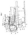
- FIG. 1 is a side cut-away view of a mechanism part of an image forming device of an embodiment of the present invention.
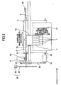
- FIG. 2 is a plan view of a main part of the image forming device shown in FIG. 1 .
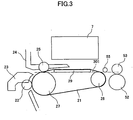
- FIG. 3 is an expanded side view of the main part of the image forming device shown in FIG. 1 .
- the image forming device includes a guide rod 1 and a stay 2 provided as guide members extending between side plates (not shown in the FIG. 1 and FIG. 2 ) on the X1 and X2 sides.
- the image forming device holds a carriage 3 by the guide rod 1 and the stay 2 so that the carriage 3 can slide in a main scanning direction or the X1 and X2 directions.
- a main scanning motor 4 drives the carriage 3 so that the carriage 3 moves and scans in the main scanning direction shown by an arrow in FIG. 2 via a timing belt 5 provided between a driving pulley 6a and an idler pulley 6b.
- Guide bushings (bearings) 3a are provided between the carriage 3 and the guide rod 1.
- the carriage 3 includes a recording head 7 composed of four ink-jet heads of yellow (Y), cyan (C), magenta (M), and black (Bk) ejecting ink droplets of respective colors.
- the recording head 7 is attached so that the ink ejection openings of the recording head 7 are arranged in a direction to cross the main scanning direction and ink is ejected from the ink ejection openings in the downward direction.
- the ink jet head forming the recording head 7 may have a piezoelectric actuator such as a piezoelectric element, a thermal actuator which uses phase changes due to film boiling of liquid by using an electric thermal conversion element such as an exothermic resistor, a shape memory alloy actuator which uses metal phase changes based on temperature changes, or an electrostatic actuator which uses an electrostatic force, as an energy generation part configured to jet the ink (recording liquid).
- a piezoelectric actuator such as a piezoelectric element
- a thermal actuator which uses phase changes due to film boiling of liquid by using an electric thermal conversion element such as an exothermic resistor
- a shape memory alloy actuator which uses metal phase changes based on temperature changes
- an electrostatic actuator which uses an electrostatic force
- the recording head 7 may be formed by a single or plural liquid drop jetting head(s) having plural nozzle lines jetting different colors.
- the carriage 3 includes sub tanks 8 of the four colors for supplying the respective color inks to the recording head 7.
- the color inks are supplied from respective main tanks (ink cartridges, not shown in FIG. 1 and FIG. 2 ) through ink supply tubes 9 to the corresponding sub tanks 8.
- a recording head configured to jet fixing process liquid (fixing ink) which reacts with the recording liquid (ink) so that a fixing ability of the ink can be improved, may be provided.
- the image forming device includes a paper feeding part configured to feed papers 12 stacked on a paper stacking part (a pressure plate) 11 of a paper feeding tray 10.
- the paper feeding part includes a crescent-shaped roller (a paper feeding roller) 13 that separates and feeds the papers 12 one by one from the paper stacking part 11 and a separation pad 14 formed of a material with a high coefficient of friction and provided to oppose the paper feeding roller 13.
- the separation pad 14 is biased toward the paper feeding roller 13.
- the image forming device also includes a conveying part configured to convey each of the recording media (papers) 12 fed from the paper feeding part below of the recording head 7.
- the conveying part includes a conveyance belt 21, a counter roller 22, a conveying guide 23, an edge pressure roller 25, and an electrostatic charging roller 26.
- the conveyance belt 21 conveys the paper 12 by causing the paper 12 to adhere electrostatically to the conveyance belt 21.
- the paper 12 is fed through a guide 15 from the paper feeding part to be conveyed and held between the conveyance belt 21 and the counter roller 22.
- the conveying guide 23 changes the conveying direction of the sheet of paper 12 fed substantially vertically in the upward direction by substantially 90 degrees so that the paper 12 is conveyed on and along the conveyance belt 21.
- the edge pressure roller 25 is biased toward the conveyance belt 21 by a holding member 24.
- the electrostatic charging roller 26 forms a charging part that charges the surface of the conveyance belt 21.
- a conveying path having an arc shaped configuration is formed between the conveying guide 23 and the conveyance belt 21 provided on the conveying roller (belt driving roller) 22 so that the direction of the paper 12 guided upward in a substantially vertical direction is changed by approximately 90 degrees. Accordingly, the surface of the conveyance path facing the conveyance belt 21 has an arc shaped configuration having a radius of curvature greater than the radius of curvature of the conveyance belt 21.
- the conveyance belt 21 is an endless belt and may be formed by connecting both ends of a belt having ends.
- the conveyance belt 21 is tensioned between the conveying roller 27 and the tension roller 28.
- the sub-scanning motor 31 rotates the conveying roller 27 via the timing belt 32 and the timing roller 33 so that the conveyance belt 21 is rotated in a belt conveyance direction of FIG. 2 , namely a sub-scanning direction.
- a guide member 29 is provided at a rear surface side of the conveyance belt 21 corresponding to an image forming area of the recording head 7.
- the conveyance belt 21 may be an endless belt having a single-layer structure as shown in FIG. 4 .
- the conveyance belt 21 may be an endless belt having a multi-layers structure as shown in FIG. 5 .
- the entirety of the conveyance belt 21 is formed by an insulation material because the conveyance belt 21 comes in contact with the paper 12 or the electrostatic charging roller 26.
- the side of the conveyance belt 21 where the conveyance belt 21 comes in contact with the paper 12 or the electrostatic charging roller 26 is formed by an insulation layer 21A and the side of the conveyance belt 21 where the conveyance belt 21 does not come in contact with the paper 12 or the electrostatic charging roller 26 is formed by a conductive layer 21B.
- an insulation layer forming the conveyance belt 21 having the single layer structure or forming the conveyance belt 21 having the multi-layer structure be resin such as PET, PEI, PVDF, PC, ETFE, or PTFE or an elastomer not including a conductive control material.
- the insulation layer have a volume resistivity equal to or greater than 10 12 [ ⁇ cm] . More preferably, the insulation layer has a volume resistivity of 10 15 [ ⁇ cm] .
- the conductive layer 21B of the conveyance belt 21 having the multi-layer structure be made of the same resin or elastomer including carbon, and the volume resistivity of the conductive layer 21B be 10 5 through 10 7 [ ⁇ cm].
- the electrostatic charging roller 26 comes in contact with the insulation layer 21A being a surface layer of the conveyance belt 21 in the case of a multi-layer belt and is rotated by the rotation of the conveyance belt 21.
- the electrostatic charging roller 26 has force applied to both ends of a shaft.
- the electrostatic charging roller 26 is formed by a conductive member having a volume resistivity of 10 6 through 10 9 [ ⁇ cm] .
- An AC bias supply part 114 configured to apply, for example, AC bias of ⁇ 2 kV to the electrostatic charging roller 26 is connected to the electrostatic charging roller 26.
- the AC bias applied to the electrostatic charging roller 26 may have various wave shapes such as a sine wave or a delta wave. However, it is preferable that the AC bias have a square wave.
- the upper surface of the guide member is mounted in a state to project to the recording head 7 side with respect to the tangent line between the rollers 27 and 28 so that flatness of plane surface of the conveyance belt 21 can be secured with high precision.
- a slit disk 34 is provided at a shaft of the conveyance roller 27.
- a sensor 35 configured to detect the slits of the slit disk 34 and the slit disk 34 form an encoder 36.
- an encoder scale 42 having a slit is provided at a front side of the carriage 3.
- An encoder sensor 43 being a transmission type photo sensor configured to detect the slit of the encoder scale 42 is provided at the front surface side of the carriage 3.
- the encoder scale 42 and the encoder sensor 43 form an encoder configured to detect a main scanning direction position of the carriage 3.
- the separation claw 51 separates the paper 12 from the conveyance belt 21.
- the paper discharge roller 53 is a spur roller having a star-shaped cross-section.
- the discharged papers 12 are stacked in the paper discharge tray 54.
- a spur 55 is provided so as to face the tension roller 28 and press the printed paper 12 conveyed to the paper discharge part by the conveyance belt 21.
- a both sides paper feeding unit 61 is detachably provided at a rear side.
- the both sides paper feeding unit 61 takes in the paper 12 returned by a reverse rotation of the conveyance belt 21 and reverses the paper 12 so as to feed the paper 12 again between the counter roller 22 and the conveyance belt 21.
- an extension tray 70 can be attached at a bottom part of the image forming device, as well as the paper feeding tray 10, a pressure plate (paper stacking part) 71 where the papers are stacked, a paper feeding roller 73, and a separation pad 72.
- the paper feeding roller 73 and the separation pad 72 separate and feed the papers 12 one by one and the conveyance rollers 75 and 76 send the paper from a lower part of the device main part to a space between the counter roller 22 and the conveyance belt 21.
- a surface resistance meter 80 is provided in a paper feeding path of the paper 12, more specifically at a side in the main scanning direction of the paper feeding roller 13, so that a surface resistivity of the fed paper 12 is measured.
- the papers 12 are separated and fed from the paper discharge part one by one.
- the paper 12 fed to the upper part in a substantially vertical direction is guided by the guide 15 and clamped and conveyed by the conveyance belt 21 and the counter roller 22.
- the head end of the paper 12 is guided by the conveyance guide 23.
- the paper 12 is pressed to the conveyance belt 21 by the head end pressing roller 25 and the conveyance direction of the paper 12 is changed by substantially 90 degrees.
- a positive output and a negative output are alternately and repeatedly applied to the charging roller 26.
- an alternating voltage is applied so that positive and negative electrical charges are applied to the conveyance belt 21 in a rotation direction, namely a sub scanning direction, forming belts at a designated width.
- the paper 12 When the paper 12 is fed on the conveyance belt 21 that has alternately charged positive and negative belts, the paper 12 is adhered to the conveyance belt 21 by the electrostatic force.
- the paper 12 is conveyed in the sub-scanning direction by rotational moving of the conveyance belt 21.
- Ink drops of a single line are jetted to the stopped paper 12 for recording by driving the recording head 7 corresponding to the image signal while the carriage 3 is moved in the main scanning direction.
- recording for next line is performed.
- a recording finishing signal or a signal indicating that a rear end of the paper 12 reaches a recording area is received, so that the recording operation is finished and the paper 12 is discharged to the paper discharge tray 54.
- the conveyance belt 21 is reverse-rotated so that the paper where recording is completed is sent in the both sides paper feeding unit 61.
- the paper 12 is reversed so that a second surface is now a printing surface and the paper 12 is fed again between the counter roller 22 and the conveyance belt 21.
- the timing control is performed and the paper 12 is conveyed on the conveyance belt 21 for printing the rear surface (second surface) and then the paper 12 is discharged to the paper discharge tray 54.
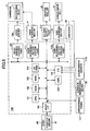
- FIG. 6 is a block diagram for explaining a schematic structure of the control part of the image forming device shown in FIG. 1 .
- This control part 100 includes a CPU 101, a ROM 102, a RAM 103, a nonvolatile memory 104, and an ASIC 105.
- the CPU 101 controls the entirety of the image forming device.
- a program performed by the CPU 101 and other fixed data are stored in the ROM 102.
- Image data and others are stored in the RAM 103 for a time.
- the nonvolatile memory 104 is rewritable so that the data are stored even when the electric power of the device is cut off.
- the ASIC 105 performs various signal processing of the image data, image processing for changing the arrangement of the data, and processing of input/output signals for controlling the entirety of the device.
- This control part 100 also includes an I/F 106, head driving parts 107 and 108, a main scanning motor driving part 111, a sub-scanning motor driving part 113, an environmental sensor 118, an I/O 116, and others.
- the I/F 106 transmits and receives data or a signal to and from a host 90 that is a data processing device such as a personal computer.
- the head driving control parts 107 and 108 perform driving control of the recording head 7.
- the main scanning motor driving part 111 drives the main scanning motor 4.
- the sub-scanning motor driving part 113 drives the sub-scanning motor 31.
- the environmental sensor 118 detects the environmental temperature and moisture via the encoder 36.
- the I/O 116 inputs a detection signal from various kinds of sensors such as a surface resistance meter 80 detecting the surface resistance value of the recording medium or the encoder 44.
- An operations panel 117 is connected to the control part 100.
- the operations panel 117 is used for inputting and displaying information necessary for this device.
- the control part 100 controls turning on or off of output of the AC bias supply part (high voltage power supply) 114 configured to apply the AC bias to the charging roller 26.
- the control part 100 receives printing data including image data from the host 90 via a cable or network by the I/F 106.
- the host 90 corresponds to a data processing device such as a personal computer, an image reading device such as an image scanner, a photographing device such as a digital camera, and others.
- An output of the printing data to the control part 100 is performed by the printer driver 91 at the host 90.
- the CPU 101 reads and analyzes the printing data in a receiving buffer included in the I/F 106 and performs the process of changing the arrangement of the data by using the ASIC 105 so as to transfer the image data to the head driving control part 107.
- the conversion of the printing data for image outputting to bit map data is transferred to this device by developing the image data to the bit map data by the printer driver 91 at the host 90 side in this example, the conversion of the printing data for image outputting to the bit map data may be performed by storing the font data in the RAM, for example.
- the head driving control part 107 When receiving the image data (dot pattern data) corresponding to a single line of the recording head 7, the head driving control part 107 synchronizes the dot pattern data of the single line to the clock signal so as to send the serial data to the head driver 108 and send a latch signal to the head driver 108 at a designated timing.
- This head driving control part 107 includes a ROM (which may be the ROM 102) storing pattern data of a driving wave form (driving signal) and a driving waveform generation circuit including an amplifier and a waveform generation circuit including a D/A converter configured to perform D/A conversion of driving waveform data read by this ROM.
- a ROM which may be the ROM 102
- driving waveform generation circuit including an amplifier
- a waveform generation circuit including a D/A converter configured to perform D/A conversion of driving waveform data read by this ROM.
- the head driver 108 includes a shift register, a latch circuit, a level conversion circuit (level shifter), an analog switch array (switch means), and others.
- the shift register inputs a clock signal from the head driving control part 107 and serial image data.
- the latch circuit latches the register value of the shift register by the latch signal from the head driving control part 107.
- the level conversion circuit performs a level change of an output value of the latch circuit.
- the level shifter controls turning on or off of the analog switch array.
- the head driver 108 controls turning on or off of the analog switch array so that the designated driving wave form included in the driving waveforms is selectively applied in the actuator part of the recording head 14 so that the recording head 14 is driven.
- the main scanning motor driving part 111 calculates a control value based on an object value received from the CPU 101 and a speed detection value obtained by sampling the detection pulse from the encoder 44 so as to drive the main scanning motor 4 via an inside motor driver.
- the sub-scanning motor driving part 113 calculates a control value based on an object value received from the CPU 101 and a speed detection value obtained by sampling the detection pulse from the encoder 36 so as to drive the sub-scanning motor 31 via an inside motor driver.
- FIG. 7 is a schematic view of a part related to electrostatic charging control of the image forming device shown in FIG. 1 .
- the amount of rotation is detected by the encoder 36 provided at an end part of the conveyance roller 27 driving the conveyance belt 21.
- the sub-scanning motor 31 is drive-controlled by the sub-scanning motor driving part 113 of the control part 100 and output of the AC bias supply part (high voltage power supply) 114 applying a high voltage (AC bias) to the charging roller 26 is controlled.
- the AC bias supply part 114 controls a cycle (application time) of positive and negative voltages applied to the charging roller 26 and simultaneously the control part 100 controls driving of the conveyance belt 21, so that positive and negative electrical charges can be applied to the conveyance belt 21 at a designated charging cycle length.
- the "charging cycle length” means a width (length) in a conveyance direction per one cycle of positive and negative application voltages as shown in FIG. 7 .
- the conveyance roller 27 is rotated by the sub-scanning motor 31 so that the conveyance belt 21 moves clockwise in FIG. 1 .
- positive and negative square waves are applied from the AC bias supply part 114 to the charging roller 26.
- the insulation layer 21A of the conveyance belt 21 where the positive and negative electrical charges are applied have a volume resistivity equal to or greater than 10 12 [ ⁇ cm] . More preferably, the insulation layer has a volume resistivity of 10 15 [ ⁇ cm] . Hence, it is possible to prevent the positive and negative electrical charges from moving at a boundary so that the positive and negative electrical charges applied to the insulation layer 21A can be held.
- Each of the papers 12 is separated by the paper feeding roller 13 and the separation pad 14.
- the paper 12 is conveyed to the conveyance belt 21 where the non-uniform electrical field is generated due to the formation of the positive and negative electrical charges at the insulation film 21A.
- the paper 12 conveyed on the non-uniform electrical field is polarized immediately along the direction of the electrical field.
- the electrical charge causing an attracting force of the conveyance belt is dense due to the non-uniform electrical field.
- the electrical charge causing a repulsion force on the conveyance belt 21 appearing at the opposite side is non-dense.
- the paper 12 is immediately adhered to the conveyance belt 21 due to the difference of the electrical charges. In addition, since the paper 12 has limited resistance, a true charge is induced at the adhering surface and opposite side of the paper 12.
- the paper 12 has a limited surface resistivity of 10 7 [ ⁇ ] through 10 13 [ ⁇ ]. Hence, the true electrical charge induced at the adhesion side and the opposite side of the paper 12 can move and neighboring positive and negative electrical charges pull against each other as time passes so that neutralizing occurs and the number of the electrical charges is decreased.
- the electrical charges on the conveyance belt 21 are balanced with the true electrical charges induced at the adhering surface side of the paper 12 so that the electrical field is closed.
- the true electrical charges induced at a side opposite to the adhering surface of the paper 12 are neutralized so that the electrical field is closed. In other words, the electrical field toward the recording head 7 is reduced.
- the carriage 3 reciprocates in a main scanning direction, and simultaneously ink liquid drops are jetted from the recording head 7, so that the image is formed on the paper 12by reciprocating movement of the recording head 7.
- the paper 12 After the image is formed on the paper 12by reciprocating movement of the recording head 7, the paper 12 is sent to next printing position by the conveyance belt 21 and the image is formed again by reciprocating movement of the recording head 7.
- the paper 12 is separated from the conveyance belt 21 by the separation claw 51 so as to be discharge to the paper discharge tray 54.
- FIG. 10 is an expanded side view of a conveyance belt unit part.
- the conveyance unit includes the conveyance belt 21, the conveyance guide plate 29, and the electrical charging roller 26.
- the conveyance belt 21 is tensioned between the conveyance roller (belt driving roller) 27 and the tension roller 28.
- the conveyance guide plate 29 is provided in a printing area facing the recording head 7 inside of the conveyance belt 21.
- the conveyance guide plate 29 guides the conveyance belt 21 from the inside as a guide part or guide means.
- the electrical charging roller 26 charges the conveyance belt 21 for electrostatically charging the paper 12 to adhere to the conveyance belt 21 for conveying, as a charging part or charging means. More specifically, in this example, the electrical charging roller 26 charges the insulation layer 21A being a surface layer of the conveyance belt 21.
- the conveyance guide plate 29 is mounted in a state to project to the recording head 7 side with respect to the tangent line between the rollers 27 and 28 so that flatness of plane surface 221A of the conveyance belt 21 is secured in the arèa of the conveyance guide plate 29.
- the tilt surface 221B is tilted downward in an area separated from the conveyance guide plate 29 and toward the tension roller 28.
- the tilt surface 221B is tilted downward in an area separated from the conveyance guide plate 29 and toward the tension roller 28.
- the paper 12 electrostatically adhered to the conveyance belt 12 is separated from the conveyance belt 12 and the electrostatic attraction force becomes zero.
- the paper 12 is immediately separated even from a part of the recording head 7.
- the relationship between the tension roller 28 and the conveyance guide plate 29 is that the recording medium 12 adhered to the conveyance belt 21 by the electrostatic force is not separated from the conveyance belt 21 at an angle ⁇ 1 formed by the flat surface of the conveyance belt 21 facing the recording head 7 and the tilt surface 221B tilted downward in a downstream side of the recording head 7.
- the alternate electric charges were applied so that the paper 12 is adhered on the conveyance belt 12.
- the attraction forces in a case of single side printing and of a second surface in a case of both sides printing were measured. As shown in FIG. 11, 10 N was measured as the attraction force in the case of the single side printing, and 5 N was measured due to the moisture of the ink in the first surface as the attraction force in the case of the both sides printing.
- the single side printing and the both sides printing are performed by changing the angle ⁇ 1 and the angle at which the paper is not separated from the conveyance belt 21 is evaluated.
- the results of this are shown in FIG. 12 (in the case of the single side printing) and FIG. 13 (in the case of the both sides printing).
- the position relationship between the conveyance guide plate 29 and the tension roller 28 be set so that the angle ⁇ 1 does not exceed 5 degrees.
- the paper 12 can be conveyed to the paper discharge part by preventing the paper from being separated at the tilt surface 221B of the conveyance belt 21 so that a high quality image can be stably, formed.
- the position relationship between the conveyance guide plate 29 and the tension roller 28 be set so that the angle ⁇ 1 does not exceed 3 degrees.
- the paper 12 can be conveyed to the paper discharge part by preventing the paper from being separated at the tilt surface 221B of the conveyance belt 21 so that a high quality image can be stably formed.
- the position relationship between the conveyance guide plate 29 and the tension roller 28 be set so that the angle ⁇ 1 does not exceed 5 degrees. As a result of this, the separation of the paper 12 at the tilt surface 221B of the conveyance belt 21 is prevented.
- the above-discussed angle ⁇ 1 be smaller than an angle ⁇ 2 formed by the flat surface 221A of the conveyance belt 21 facing the recording head 7 and the tilt surface 221C tilted downward in an upstream side of the recording head 7 ( ⁇ 1 ⁇ ⁇ 2).
- the paper 12 can be pressed by a pressing roller at the tilt surface 221c side. Even if there is some angles at the tilt surface 221C side, it is possible to forcibly press the paper 12 to the conveyance belt 21.
- the paper 12 is expanded due to the moisture so that the paper waviness is generated in a direction crossing the paper feeding direction. If the paper waviness reaches to the recording head 7, the printed image may be damaged due to abrasion of the recording head 7 and the paper 12.
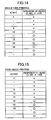
- the length a of the surface where the conveyance belt 21 at the downstream side of the plane surface of the conveyance guide plate 29 shown in FIG. 10 is formed is changed so that the relationship between the length a and the abrasion of the recording head with the paper where a designated amount of ink (maximum amount of standard amount of the ink in this case) are printed is measured. The result of this is shown in FIG. 14 and FIG. 15 .
- the attraction force is 10 N (See FIG. 10 .) and the length a at which the abrasion between the recording head 7 and the paper due to the expansion of the paper due to the moisture is not generated is equal to or greater than 10 mm.
- the attraction force is 5 N due to the moisture in the ink in the first surface and the length a at which the abrasion between the recording head 7 and the paper is not generated is equal to or greater than 12 mm.
- the maximum value of the length a be equal to or less than 100 mm.
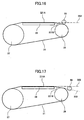
- FIG. 16 is an expanded side view of a main part of the conveyance belt unit.
- the spur 55 is provided so as to press the paper conveyed to a position lower than the extended line 302 of the flat surface 221A of the conveyance belt.
- the spur 55 is provided at a position facing the tilt surface 221B of the conveyance belt 21. Because of this, it is possible to prevent the paper 12 from being separated from the tilt surface 221B of the conveyance belt 21. In this case, the paper can be securely pressed so that the separation of the paper can be securely prevented, by facing the spur 55 to the tension roller 28 hanging on the downstream side in the paper conveyance direction of the conveyance belt 21.
- FIG. 17 is an expanded side view of a main part of the conveyance belt unit.
- the spur 55 is provided so as to press the paper conveyed to a position lower than the extended line 302 of the flat surface 221A of the conveyance belt. As a result of this, it is possible to prevent the paper 12 conveyed by the conveyance belt 21 from being separated from the flat surface 221A of the conveyance belt 21.
- the spur 55 is provided at a position lower than the extended line 303 of the tilt surface 221B of the conveyance belt 21. Under this structure, it is possible to prevent the paper 12 from being separated from the tilt surface 221B of the conveyance belt 21.
Landscapes
- Ink Jet (AREA)
- Feeding Of Articles By Means Other Than Belts Or Rollers (AREA)
- Handling Of Sheets (AREA)
Description
- The present invention generally relates to image forming devices, and more specifically, to an image forming device having a conveyance belt configured to convey a recording medium.
- An inkjet recording device, for example, is known as an image forming device such as a printer, facsimile, copier or a multiple function processing machine of the printer, facsimile, and copier. In the above-mentioned inkjet recording device, while a recording medium is conveyed, a liquid drop of recording liquid (hereinafter "ink drop") is adhered to the recording medium by using a recording head (image forming part) having a liquid jet head configured to jet the liquid drop of the recording liquid, so that image forming such as recording or printing is performed. Hereinafter, the recording medium is called a paper or transferred material. However, there is no limitation of material for the paper or the transferred material.
- In the meantime, in a case where an image is formed by an ink jet recording method, ink adheres to paper. Therefore, when an image is formed on the paper, moisture included in the ink causes the paper to stretch. This phenomenon is referred to as cockling.
- Cockling causes paper waviness so that the distance between the nozzle of a recording head and a paper surface varies depending on the position on the paper surface. Cockling may worsen to such an extent that, in the worst case, the paper comes into contact with the nozzle surface of the recording head.
- As a result, not only the nozzle surface of the recording head but also the paper itself may be contaminated so that image quality is degraded. In addition, due to cockling, a portion in the paper where the ink drop adheres may be shifted.
- In the related art inkjet recording devices, feeding of the paper is performed by using two groups of rollers arranged one group at each end of a printing area. With this structure, however, it is difficult to obtain high feeding precision unless the printing sheet is firmly in contact with both of the groups of rollers.
- However, recently, a larger image forming area has become required, and in order to increase the printing area, there is proposed an inkjet image recording device having only one group of rollers for feeding the printing sheet.
- However, such a device makes it even more difficult to obtain high feeding precision. Specifically, with the printing sheet being in contact with the rollers at only one side, the printing sheet floats relative to the rollers sometimes, and a force for conveying the printing sheet cannot be obtained. Consequently, the feeding precision becomes low, and the image quality declines.
- Therefore, inkjet recording devices are proposed to solve this problem in which, in order to maintain flatness of the printing sheet, a charged seamless belt is provided to hold the paper on the belt by an electrostatic force due to the charge, and the belt is rolled in this state to convey the paper. In this way, floating of the paper from the belt is preventable and good flatness can be obtained.
- Meanwhile, in the inkjet recording device in which the printing sheet is fed while being held on the feeding belt by an electrostatic force, the flatness of the paper is directly related to flatness of the belt.
- In addition, in the above-mentioned inkjet recording device of the related art, the feeding belt is tensioned by at least two rollers and the portion of the belt between the rollers corresponds to the printing area, that is, the area printed on by the inkjet head. This portion of the belt rumples easily, and oscillates in a direction perpendicular to the belt surface when the belt is rolled, causing declination of flatness of the belt.
- Thus, since generally the flatness of the printing sheet is directly related to flatness of the belt, the distance between the recording head and the printing sheet changes, causing image quality to decline.
- Japanese Laid-Open Patent Application Publication No.
2004-175494 - However, as discussed in Japanese Laid-Open Patent Application Publication No.
2004-175494 - The inventors of the present invention examined the reason for this problem and found that the conveyance belt passing over the guide member is supported so that it is tilted downward and to the roller because the upper surface of the guide member is mounted to project to the recording head side with respect to the tangent line between the rollers for securing the flatness of the conveyance belt in the area facing the recording head. As a result of this, it is found that this problem is related to the paper being easily self-stripped.
- Especially, in a case where the paper is adhered to the conveyance belt by the electrostatic force, if a head end of the paper is separated from the conveyance belt, the electrostatic force does not work and the paper may be immediately separated. In addition, since the moisture is not sufficiently dried at the time when the second surface of the paper is both-sides printed, the paper including a relatively large amount of the moisture such as when set-solid printing is applied, the attraction force between the paper and the conveyance belt becomes low so that self stripping may easily happen.
- Furthermore, when the ink adheres to the paper adhered by the conveyance belt, the paper may expand due to the moisture so that the paper waviness in a direction crossing the conveyance direction may be generated. When the paper is separated from the conveyance belt at the downstream side of the guide member, the paper waviness reaches back to the guide member part so that the abrasion between the recording head and the paper may happen, in which case the image receives damage.
-
WO 2004/048240 discloses an inkjet recording device with a conveyance belt and a guide unit arranged to push a portion of a conveyance belt from the innerside to approach the recording unit. - Accordingly, in a preferred embodiment of the present invention there is provided a novel and useful image forming device solving one or more of the problems discussed above.
- According to one aspect of the present invention there is provided an image forming device as defined in the appended claims. In this device a high quality image can be stably formed by preventing separation of a recording medium from a conveyance belt or by preventing abrasion with a recording head due to the separation.
- According to the above-mentioned image forming device, it is possible to prevent the recording medium from being separated from the conveyance belt at the downstream side of the recording head and thereby it is possible to stably form the high quality image.
- Other objects, features, and advantages of the present invention will become more apparent from the following detailed description when read in conjunction with the accompanying drawings.
-
FIG. 1 is a side cut-away view of a mechanism part of an image forming device of an embodiment of the present invention; -
FIG. 2 is a plan view of a main part of the image forming device shown inFIG. 1 ; -
FIG. 3 is an expanded side view of the main part of the image forming device shown inFIG. 1 ; -
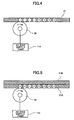
FIG. 4 is a view showing an example of a conveyance belt of the image forming device shown inFIG. 1 ; -
FIG. 5 is a view showing another example of a conveyance belt of the image forming device shown inFIG. 1 ; -
FIG. 6 is a block diagram for explaining a schematic structure of a control part of the image forming device shown inFIG. 1 ; -
FIG. 7 is a schematic view of a part related to electrostatic charging control of the image forming device shown inFIG. 1 ; -
FIG. 8 is a schematic view for explaining that the conveyance belt is electrostatically charged; -
FIG. 9 is a schematic view for explaining the paper coming in contact with the conveyance belt; -
FIG. 10 is an expanded side view of a conveyance belt unit part; -
FIG. 11 is a table for explaining the relationship between a printing mode and the result of measurement of attraction of the paper by the conveyance belt; -
FIG. 12 is a table for explaining an example of the relationship between an angle θ1 inFIG. 10 and the result of measurement of separation of the paper from the conveyance belt in a single side printing mode; -
FIG. 13 is a table for explaining an example of the relationship between an angle θ1 inFIG. 10 and the result of measurement of separation of the paper from the conveyance belt in a both sides printing mode; -
FIG. 14 is a table for explaining an example of the relationship between a length a inFIG. 10 and the result of measurement of existence of head abrasion in the single side printing mode; -
FIG. 15 is a table for explaining an example of the relationship between a length a inFIG. 10 and the result of measurement of existence of head abrasion in the both sides printing mode; -
FIG. 16 is an expanded side view of a main part for explaining an example of an arranged position of a spur; and -
FIG. 17 is an expanded side view of a main part for explaining another example of the arranged position of the spur. - A description of the present invention is now given, with reference to
FIG. 1 through FIG. 17 , including embodiments of the present invention. - First, an image forming device of an embodiment of the present invention is discussed with reference to
FIG. 1 through FIG. 3 . - Here,
FIG. 1 is a side cut-away view of a mechanism part of an image forming device of an embodiment of the present invention.FIG. 2 is a plan view of a main part of the image forming device shown inFIG. 1 .FIG. 3 is an expanded side view of the main part of the image forming device shown inFIG. 1 . - Referring to
FIG. 1 andFIG. 2 , the image forming device includes aguide rod 1 and astay 2 provided as guide members extending between side plates (not shown in theFIG. 1 andFIG. 2 ) on the X1 and X2 sides. The image forming device holds acarriage 3 by theguide rod 1 and thestay 2 so that thecarriage 3 can slide in a main scanning direction or the X1 and X2 directions. - A
main scanning motor 4 drives thecarriage 3 so that thecarriage 3 moves and scans in the main scanning direction shown by an arrow inFIG. 2 via atiming belt 5 provided between a drivingpulley 6a and an idler pulley 6b. Guide bushings (bearings) 3a are provided between thecarriage 3 and theguide rod 1. - The
carriage 3 includes arecording head 7 composed of four ink-jet heads of yellow (Y), cyan (C), magenta (M), and black (Bk) ejecting ink droplets of respective colors. Therecording head 7 is attached so that the ink ejection openings of therecording head 7 are arranged in a direction to cross the main scanning direction and ink is ejected from the ink ejection openings in the downward direction. - The ink jet head forming the
recording head 7 may have a piezoelectric actuator such as a piezoelectric element, a thermal actuator which uses phase changes due to film boiling of liquid by using an electric thermal conversion element such as an exothermic resistor, a shape memory alloy actuator which uses metal phase changes based on temperature changes, or an electrostatic actuator which uses an electrostatic force, as an energy generation part configured to jet the ink (recording liquid). - The
recording head 7 may be formed by a single or plural liquid drop jetting head(s) having plural nozzle lines jetting different colors. - The
carriage 3 includessub tanks 8 of the four colors for supplying the respective color inks to therecording head 7. The color inks are supplied from respective main tanks (ink cartridges, not shown inFIG. 1 andFIG. 2 ) throughink supply tubes 9 to thecorresponding sub tanks 8. - Other than the
recording head 7 jetting the link drop, a recording head configured to jet fixing process liquid (fixing ink) which reacts with the recording liquid (ink) so that a fixing ability of the ink can be improved, may be provided. - In addition, the image forming device includes a paper feeding part configured to feed
papers 12 stacked on a paper stacking part (a pressure plate) 11 of apaper feeding tray 10. - The paper feeding part includes a crescent-shaped roller (a paper feeding roller) 13 that separates and feeds the
papers 12 one by one from thepaper stacking part 11 and aseparation pad 14 formed of a material with a high coefficient of friction and provided to oppose thepaper feeding roller 13. Theseparation pad 14 is biased toward thepaper feeding roller 13. - The image forming device also includes a conveying part configured to convey each of the recording media (papers) 12 fed from the paper feeding part below of the
recording head 7. The conveying part includes aconveyance belt 21, acounter roller 22, a conveyingguide 23, anedge pressure roller 25, and anelectrostatic charging roller 26. - The
conveyance belt 21 conveys thepaper 12 by causing thepaper 12 to adhere electrostatically to theconveyance belt 21. Thepaper 12 is fed through aguide 15 from the paper feeding part to be conveyed and held between theconveyance belt 21 and thecounter roller 22. - The conveying
guide 23 changes the conveying direction of the sheet ofpaper 12 fed substantially vertically in the upward direction by substantially 90 degrees so that thepaper 12 is conveyed on and along theconveyance belt 21. Theedge pressure roller 25 is biased toward theconveyance belt 21 by a holdingmember 24. Theelectrostatic charging roller 26 forms a charging part that charges the surface of theconveyance belt 21. - A conveying path having an arc shaped configuration is formed between the conveying
guide 23 and theconveyance belt 21 provided on the conveying roller (belt driving roller) 22 so that the direction of thepaper 12 guided upward in a substantially vertical direction is changed by approximately 90 degrees. Accordingly, the surface of the conveyance path facing theconveyance belt 21 has an arc shaped configuration having a radius of curvature greater than the radius of curvature of theconveyance belt 21. - The
conveyance belt 21 is an endless belt and may be formed by connecting both ends of a belt having ends. Theconveyance belt 21 is tensioned between the conveyingroller 27 and thetension roller 28. Thesub-scanning motor 31 rotates the conveyingroller 27 via thetiming belt 32 and thetiming roller 33 so that theconveyance belt 21 is rotated in a belt conveyance direction ofFIG. 2 , namely a sub-scanning direction. - A
guide member 29 is provided at a rear surface side of theconveyance belt 21 corresponding to an image forming area of therecording head 7. - The
conveyance belt 21 may be an endless belt having a single-layer structure as shown inFIG. 4 . Theconveyance belt 21 may be an endless belt having a multi-layers structure as shown inFIG. 5 . - In the case of the
conveyance belt 21 having the single-layer structure, the entirety of theconveyance belt 21 is formed by an insulation material because theconveyance belt 21 comes in contact with thepaper 12 or theelectrostatic charging roller 26. - In the case of the
conveyance belt 21 having the multi-layer structure, it is preferable that the side of theconveyance belt 21 where theconveyance belt 21 comes in contact with thepaper 12 or theelectrostatic charging roller 26 is formed by aninsulation layer 21A and the side of theconveyance belt 21 where theconveyance belt 21 does not come in contact with thepaper 12 or theelectrostatic charging roller 26 is formed by aconductive layer 21B. - It is preferable that an insulation layer forming the
conveyance belt 21 having the single layer structure or forming theconveyance belt 21 having the multi-layer structure be resin such as PET, PEI, PVDF, PC, ETFE, or PTFE or an elastomer not including a conductive control material. - It is also preferable that the insulation layer have a volume resistivity equal to or greater than 1012 [Ωcm] . More preferably, the insulation layer has a volume resistivity of 1015 [Ωcm] .
- It is also preferable that the
conductive layer 21B of theconveyance belt 21 having the multi-layer structure be made of the same resin or elastomer including carbon, and the volume resistivity of theconductive layer 21B be 105 through 107 [Ωcm]. - The
electrostatic charging roller 26 comes in contact with theinsulation layer 21A being a surface layer of theconveyance belt 21 in the case of a multi-layer belt and is rotated by the rotation of theconveyance belt 21. Theelectrostatic charging roller 26 has force applied to both ends of a shaft. - The
electrostatic charging roller 26 is formed by a conductive member having a volume resistivity of 106 through 109 [Ωcm] . An ACbias supply part 114 configured to apply, for example, AC bias of ±2 kV to theelectrostatic charging roller 26 is connected to theelectrostatic charging roller 26. The AC bias applied to theelectrostatic charging roller 26 may have various wave shapes such as a sine wave or a delta wave. However, it is preferable that the AC bias have a square wave. - As shown in
FIG. 3 , the upper surface of the guide member is mounted in a state to project to therecording head 7 side with respect to the tangent line between therollers conveyance belt 21 can be secured with high precision. - In addition, as shown in
FIG. 2 , aslit disk 34 is provided at a shaft of theconveyance roller 27. Asensor 35 configured to detect the slits of theslit disk 34 and theslit disk 34 form anencoder 36. - As shown in
FIG. 1 , anencoder scale 42 having a slit is provided at a front side of thecarriage 3. Anencoder sensor 43 being a transmission type photo sensor configured to detect the slit of theencoder scale 42 is provided at the front surface side of thecarriage 3. Theencoder scale 42 and theencoder sensor 43 form an encoder configured to detect a main scanning direction position of thecarriage 3. - As a paper discharge part configured to discharge the
paper 12 recorded on by therecording head 7, there are aseparation claw 51,paper discharge rollers paper discharge tray 54. Theseparation claw 51 separates thepaper 12 from theconveyance belt 21. - The
paper discharge roller 53 is a spur roller having a star-shaped cross-section. The dischargedpapers 12 are stacked in thepaper discharge tray 54. Although details are discussed below, aspur 55 is provided so as to face thetension roller 28 and press the printedpaper 12 conveyed to the paper discharge part by theconveyance belt 21. - A both sides
paper feeding unit 61 is detachably provided at a rear side. The both sidespaper feeding unit 61 takes in thepaper 12 returned by a reverse rotation of theconveyance belt 21 and reverses thepaper 12 so as to feed thepaper 12 again between thecounter roller 22 and theconveyance belt 21. - In addition, an
extension tray 70 can be attached at a bottom part of the image forming device, as well as thepaper feeding tray 10, a pressure plate (paper stacking part) 71 where the papers are stacked, apaper feeding roller 73, and aseparation pad 72. - In a case of paper feeding, the
paper feeding roller 73 and theseparation pad 72 separate and feed thepapers 12 one by one and theconveyance rollers counter roller 22 and theconveyance belt 21. - A
surface resistance meter 80 is provided in a paper feeding path of thepaper 12, more specifically at a side in the main scanning direction of thepaper feeding roller 13, so that a surface resistivity of the fedpaper 12 is measured. - In the image forming device having the above-discussed structure, the
papers 12 are separated and fed from the paper discharge part one by one. Thepaper 12 fed to the upper part in a substantially vertical direction is guided by theguide 15 and clamped and conveyed by theconveyance belt 21 and thecounter roller 22. - In addition, the head end of the
paper 12 is guided by theconveyance guide 23. Thepaper 12 is pressed to theconveyance belt 21 by the headend pressing roller 25 and the conveyance direction of thepaper 12 is changed by substantially 90 degrees. - At this time, a positive output and a negative output are alternately and repeatedly applied to the charging
roller 26. In other words, an alternating voltage is applied so that positive and negative electrical charges are applied to theconveyance belt 21 in a rotation direction, namely a sub scanning direction, forming belts at a designated width. - When the
paper 12 is fed on theconveyance belt 21 that has alternately charged positive and negative belts, thepaper 12 is adhered to theconveyance belt 21 by the electrostatic force. Thepaper 12 is conveyed in the sub-scanning direction by rotational moving of theconveyance belt 21. - Ink drops of a single line are jetted to the stopped
paper 12 for recording by driving therecording head 7 corresponding to the image signal while thecarriage 3 is moved in the main scanning direction. - After the
paper 12 is conveyed at a designated length, recording for next line is performed. A recording finishing signal or a signal indicating that a rear end of thepaper 12 reaches a recording area is received, so that the recording operation is finished and thepaper 12 is discharged to thepaper discharge tray 54. - In a case of the both sides printing, when recording on a first surface is completed, the
conveyance belt 21 is reverse-rotated so that the paper where recording is completed is sent in the both sidespaper feeding unit 61. Thepaper 12 is reversed so that a second surface is now a printing surface and thepaper 12 is fed again between thecounter roller 22 and theconveyance belt 21. - The timing control is performed and the
paper 12 is conveyed on theconveyance belt 21 for printing the rear surface (second surface) and then thepaper 12 is discharged to thepaper discharge tray 54. - Next, a control part of this image forming apparatus is discussed with reference to
FIG. 6 . Here,FIG. 6 is a block diagram for explaining a schematic structure of the control part of the image forming device shown inFIG. 1 . - This
control part 100 includes aCPU 101, aROM 102, aRAM 103, anonvolatile memory 104, and anASIC 105. - The
CPU 101 controls the entirety of the image forming device. A program performed by theCPU 101 and other fixed data are stored in theROM 102. Image data and others are stored in theRAM 103 for a time. Thenonvolatile memory 104 is rewritable so that the data are stored even when the electric power of the device is cut off. TheASIC 105 performs various signal processing of the image data, image processing for changing the arrangement of the data, and processing of input/output signals for controlling the entirety of the device. - This
control part 100 also includes an I/F 106,head driving parts motor driving part 111, a sub-scanningmotor driving part 113, anenvironmental sensor 118, an I/O 116, and others. - The I/
F 106 transmits and receives data or a signal to and from ahost 90 that is a data processing device such as a personal computer. The head drivingcontrol parts recording head 7. The main scanningmotor driving part 111 drives themain scanning motor 4. The sub-scanningmotor driving part 113 drives thesub-scanning motor 31. - The
environmental sensor 118 detects the environmental temperature and moisture via theencoder 36. The I/O 116 inputs a detection signal from various kinds of sensors such as asurface resistance meter 80 detecting the surface resistance value of the recording medium or theencoder 44. - An
operations panel 117 is connected to thecontrol part 100. Theoperations panel 117 is used for inputting and displaying information necessary for this device. In addition, thecontrol part 100 controls turning on or off of output of the AC bias supply part (high voltage power supply) 114 configured to apply the AC bias to the chargingroller 26. - The
control part 100 receives printing data including image data from thehost 90 via a cable or network by the I/F 106. Here, thehost 90 corresponds to a data processing device such as a personal computer, an image reading device such as an image scanner, a photographing device such as a digital camera, and others. An output of the printing data to thecontrol part 100 is performed by theprinter driver 91 at thehost 90. - The
CPU 101 reads and analyzes the printing data in a receiving buffer included in the I/F 106 and performs the process of changing the arrangement of the data by using theASIC 105 so as to transfer the image data to the head drivingcontrol part 107. - While the conversion of the printing data for image outputting to bit map data is transferred to this device by developing the image data to the bit map data by the
printer driver 91 at thehost 90 side in this example, the conversion of the printing data for image outputting to the bit map data may be performed by storing the font data in the RAM, for example. - When receiving the image data (dot pattern data) corresponding to a single line of the
recording head 7, the head drivingcontrol part 107 synchronizes the dot pattern data of the single line to the clock signal so as to send the serial data to thehead driver 108 and send a latch signal to thehead driver 108 at a designated timing. - This head driving
control part 107 includes a ROM (which may be the ROM 102) storing pattern data of a driving wave form (driving signal) and a driving waveform generation circuit including an amplifier and a waveform generation circuit including a D/A converter configured to perform D/A conversion of driving waveform data read by this ROM. - The
head driver 108 includes a shift register, a latch circuit, a level conversion circuit (level shifter), an analog switch array (switch means), and others. - The shift register inputs a clock signal from the head driving
control part 107 and serial image data. The latch circuit latches the register value of the shift register by the latch signal from the head drivingcontrol part 107. The level conversion circuit performs a level change of an output value of the latch circuit. The level shifter controls turning on or off of the analog switch array. - The
head driver 108 controls turning on or off of the analog switch array so that the designated driving wave form included in the driving waveforms is selectively applied in the actuator part of therecording head 14 so that therecording head 14 is driven. - The main scanning
motor driving part 111 calculates a control value based on an object value received from theCPU 101 and a speed detection value obtained by sampling the detection pulse from theencoder 44 so as to drive themain scanning motor 4 via an inside motor driver. - Similarly, the sub-scanning
motor driving part 113 calculates a control value based on an object value received from theCPU 101 and a speed detection value obtained by sampling the detection pulse from theencoder 36 so as to drive thesub-scanning motor 31 via an inside motor driver. - Electrostatic charge control of the
conveyance belt 21 in this image forming device is discussed with reference toFIG. 7 and others. Here,FIG. 7 is a schematic view of a part related to electrostatic charging control of the image forming device shown inFIG. 1 . - As discussed above, the amount of rotation is detected by the
encoder 36 provided at an end part of theconveyance roller 27 driving theconveyance belt 21. As corresponding to the detected rotation amount, thesub-scanning motor 31 is drive-controlled by the sub-scanningmotor driving part 113 of thecontrol part 100 and output of the AC bias supply part (high voltage power supply) 114 applying a high voltage (AC bias) to the chargingroller 26 is controlled. - The AC
bias supply part 114 controls a cycle (application time) of positive and negative voltages applied to the chargingroller 26 and simultaneously thecontrol part 100 controls driving of theconveyance belt 21, so that positive and negative electrical charges can be applied to theconveyance belt 21 at a designated charging cycle length. Here, the "charging cycle length" means a width (length) in a conveyance direction per one cycle of positive and negative application voltages as shown inFIG. 7 . - As discussed above, when printing starts, the
conveyance roller 27 is rotated by thesub-scanning motor 31 so that theconveyance belt 21 moves clockwise inFIG. 1 . Simultaneously, positive and negative square waves are applied from the ACbias supply part 114 to the chargingroller 26. - As a result of this, since the charging
roller 26 comes in contact with theinsulation layer 21A of theconveyance belt 21, as shown inFIG. 7 , positive and negative electrical charges are mutually applied in the conveyance direction of theconveyance belt 21 to theinsulation layer 21A of theconveyance belt 21 so that belt shapepositive charging area 201 andnegative charging area 202 are mutually formed. As a result of this, as shown inFIG. 8 , a non-uniform electrical field is generated on theconveyance belt 21. - As discussed above, it is also preferable that the
insulation layer 21A of theconveyance belt 21 where the positive and negative electrical charges are applied have a volume resistivity equal to or greater than 1012 [Ωcm] . More preferably, the insulation layer has a volume resistivity of 1015 [Ωcm] . Hence, it is possible to prevent the positive and negative electrical charges from moving at a boundary so that the positive and negative electrical charges applied to theinsulation layer 21A can be held. - Each of the
papers 12 is separated by thepaper feeding roller 13 and theseparation pad 14. Thepaper 12 is conveyed to theconveyance belt 21 where the non-uniform electrical field is generated due to the formation of the positive and negative electrical charges at theinsulation film 21A. Thepaper 12 conveyed on the non-uniform electrical field is polarized immediately along the direction of the electrical field. - As shown in
FIG. 9 , the electrical charge causing an attracting force of the conveyance belt is dense due to the non-uniform electrical field. The electrical charge causing a repulsion force on theconveyance belt 21 appearing at the opposite side is non-dense. - The
paper 12 is immediately adhered to theconveyance belt 21 due to the difference of the electrical charges. In addition, since thepaper 12 has limited resistance, a true charge is induced at the adhering surface and opposite side of thepaper 12. - The positive and negative true electrical charges induced at the adhering surface side of the
paper 12 and the electrical charges applied on theconveyance belt 21 pull against each other so that a stable attraction force can be made. - Furthermore, the
paper 12 has a limited surface resistivity of 107 [Ω] through 1013 [Ω]. Hence, the true electrical charge induced at the adhesion side and the opposite side of thepaper 12 can move and neighboring positive and negative electrical charges pull against each other as time passes so that neutralizing occurs and the number of the electrical charges is decreased. - As a result of this, the electrical charges on the
conveyance belt 21 are balanced with the true electrical charges induced at the adhering surface side of thepaper 12 so that the electrical field is closed. As discussed above, the true electrical charges induced at a side opposite to the adhering surface of thepaper 12 are neutralized so that the electrical field is closed. In other words, the electrical field toward therecording head 7 is reduced. - In addition, since the electrical charge applied on the surface of the
conveyance belt 21 and the electrical charge having a non-dense relationship with the electrical charge of theconveyance belt 21 are reduced away from the surface of thepaper 12, the attraction force of thepaper 12 to theconveyance belt 21 is increased as time passes. - As discussed above, the
paper 12 adhered by theconveyance belt 12 is conveyed below therecording head 7, thecarriage 3 reciprocates in a main scanning direction, and simultaneously ink liquid drops are jetted from therecording head 7, so that the image is formed on the paper 12by reciprocating movement of therecording head 7. - After the image is formed on the paper 12by reciprocating movement of the
recording head 7, thepaper 12 is sent to next printing position by theconveyance belt 21 and the image is formed again by reciprocating movement of therecording head 7. Thepaper 12 is separated from theconveyance belt 21 by theseparation claw 51 so as to be discharge to thepaper discharge tray 54. - Next, details of the conveyance unit are discussed with reference to
FIG. 10 . Here,FIG. 10 is an expanded side view of a conveyance belt unit part. - As discussed above, the conveyance unit includes the
conveyance belt 21, theconveyance guide plate 29, and theelectrical charging roller 26. - The
conveyance belt 21 is tensioned between the conveyance roller (belt driving roller) 27 and thetension roller 28. - The
conveyance guide plate 29 is provided in a printing area facing therecording head 7 inside of theconveyance belt 21. Theconveyance guide plate 29 guides theconveyance belt 21 from the inside as a guide part or guide means. - The
electrical charging roller 26 charges theconveyance belt 21 for electrostatically charging thepaper 12 to adhere to theconveyance belt 21 for conveying, as a charging part or charging means. More specifically, in this example, theelectrical charging roller 26 charges theinsulation layer 21A being a surface layer of theconveyance belt 21. - The
conveyance guide plate 29 is mounted in a state to project to therecording head 7 side with respect to the tangent line between therollers plane surface 221A of theconveyance belt 21 is secured in the arèa of theconveyance guide plate 29. Thetilt surface 221B is tilted downward in an area separated from theconveyance guide plate 29 and toward thetension roller 28. - Thus, when the
conveyance guide plate 29 is provided so that the flatness of plane surface of theconveyance belt 21 is secured in the printing area facing therecording head 7, thetilt surface 221B is tilted downward in an area separated from theconveyance guide plate 29 and toward thetension roller 28. As a result of this, thepaper 12 electrostatically adhered to theconveyance belt 12 is separated from theconveyance belt 12 and the electrostatic attraction force becomes zero. Hence, thepaper 12 is immediately separated even from a part of therecording head 7. - Because of this, in this embodiment, the relationship between the
tension roller 28 and theconveyance guide plate 29 is that therecording medium 12 adhered to theconveyance belt 21 by the electrostatic force is not separated from theconveyance belt 21 at an angle θ1 formed by the flat surface of theconveyance belt 21 facing therecording head 7 and thetilt surface 221B tilted downward in a downstream side of therecording head 7. - The inventors of the present invention examined this angle θ1 in detail.
- First, as discussed above, the alternate electric charges were applied so that the
paper 12 is adhered on theconveyance belt 12. The attraction forces in a case of single side printing and of a second surface in a case of both sides printing were measured. As shown inFIG. 11, 10 N was measured as the attraction force in the case of the single side printing, and 5 N was measured due to the moisture of the ink in the first surface as the attraction force in the case of the both sides printing. - Because of this, the single side printing and the both sides printing are performed by changing the angle θ1 and the angle at which the paper is not separated from the
conveyance belt 21 is evaluated. The results of this are shown inFIG. 12 (in the case of the single side printing) andFIG. 13 (in the case of the both sides printing). - According to the result shown in
FIG. 12 , in the case of the single side printing, if the angle θ1 formed by the flat surface of theconveyance belt 21 facing therecording head 7 and thetilt surface 221B tilted downward in a downstream side of therecording head 7 is greater than 5 degrees, thepaper 12 is separated from theconveyance belt 21. - On the other hand, according to the result shown in
FIG. 13 , in the case of the both sides printing, as discussed above, when the second surface is printed, the attraction force is reduced due to the moisture in the ink in the first surface. Hence, if the angle θ1 formed by the flat surface of theconveyance belt 21 facing therecording head 7 and thetilt surface 221B tilted downward in a downstream side of therecording head 7 is greater than 3 degrees, thepaper 12 is separated from theconveyance belt 21. - Accordingly, in a case where only single side printing is performed, in other words, in a case of an image forming device not having the both sides (surfaces) unit, it is preferable that the position relationship between the
conveyance guide plate 29 and thetension roller 28 be set so that the angle θ1 does not exceed 5 degrees. - As a result of this, the
paper 12 can be conveyed to the paper discharge part by preventing the paper from being separated at thetilt surface 221B of theconveyance belt 21 so that a high quality image can be stably, formed. - In addition, in a case of the image forming device having the both sides unit whereby the both sides printing can be performed, it is preferable that the position relationship between the
conveyance guide plate 29 and thetension roller 28 be set so that the angle θ1 does not exceed 3 degrees. As a result of this, thepaper 12 can be conveyed to the paper discharge part by preventing the paper from being separated at thetilt surface 221B of theconveyance belt 21 so that a high quality image can be stably formed. - Accordingly, in a case where only a single side printing is performed, in other words, in a case of an image forming device not having the both sides (surfaces) unit, it is preferable that the position relationship between the
conveyance guide plate 29 and thetension roller 28 be set so that the angle θ1 does not exceed 5 degrees. As a result of this, the separation of thepaper 12 at thetilt surface 221B of theconveyance belt 21 is prevented. - It is preferable that the above-discussed angle θ1 be smaller than an angle θ2 formed by the
flat surface 221A of theconveyance belt 21 facing therecording head 7 and thetilt surface 221C tilted downward in an upstream side of the recording head 7 (θ1 < θ2). In this case, thepaper 12 can be pressed by a pressing roller at the tilt surface 221c side. Even if there is some angles at thetilt surface 221C side, it is possible to forcibly press thepaper 12 to theconveyance belt 21. - Next, when the ink drop is adhered to the
paper 12, thepaper 12 is expanded due to the moisture so that the paper waviness is generated in a direction crossing the paper feeding direction. If the paper waviness reaches to therecording head 7, the printed image may be damaged due to abrasion of therecording head 7 and thepaper 12. - Because of this, the length a of the surface where the
conveyance belt 21 at the downstream side of the plane surface of theconveyance guide plate 29 shown inFIG. 10 is formed is changed so that the relationship between the length a and the abrasion of the recording head with the paper where a designated amount of ink (maximum amount of standard amount of the ink in this case) are printed is measured. The result of this is shown inFIG. 14 and FIG. 15 . - Through these results, it is found that there is a relationship between the expansion due to the moisture of the paper and an adhesion area of the paper. In this example, in the singe side printing, the attraction force is 10 N (See
FIG. 10 .) and the length a at which the abrasion between therecording head 7 and the paper due to the expansion of the paper due to the moisture is not generated is equal to or greater than 10 mm. - By setting this length a, in a case of the image forming device for only the single side printing, the paper waviness of the recording medium is prevented from reaching to the plane surface of the
conveyance guide plate 29 so that a high quality image can be stably formed. - On the other hand, in the case of the both sides printing, the attraction force is 5 N due to the moisture in the ink in the first surface and the length a at which the abrasion between the
recording head 7 and the paper is not generated is equal to or greater than 12 mm. - By setting this length a, in a case of the image forming device where both sides printing can be performed, the paper waviness of the recording medium is prevented from reaching the plane surface of the
conveyance guide plate 29 so that a high quality image can be stably formed. It is preferable that the maximum value of the length a be equal to or less than 100 mm. - Next, another embodiment where the paper is prevented from being separated from the conveyance belt is discussed with reference to
FIG. 16 . Here,FIG. 16 is an expanded side view of a main part of the conveyance belt unit. - As discussed above, when the
flat surface 221A of theconveyance belt 21 facing therecording head 7 and thetilt surface 221B of theconveyance belt 21 tilted downward at the downstream side of therecording head 7 are formed, thespur 55 is provided so as to press the paper conveyed to a position lower than theextended line 302 of theflat surface 221A of the conveyance belt. - By providing the
spur 55 configured to press the paper conveyed to a position lower than theextended line 302 of theflat surface 221A of the conveyance belt, it is possible to prevent thepaper 12 conveyed by theconveyance belt 21 from being separated from theflat surface 221A of theconveyance belt 21. - In addition, the
spur 55 is provided at a position facing thetilt surface 221B of theconveyance belt 21. Because of this, it is possible to prevent thepaper 12 from being separated from thetilt surface 221B of theconveyance belt 21. In this case, the paper can be securely pressed so that the separation of the paper can be securely prevented, by facing thespur 55 to thetension roller 28 hanging on the downstream side in the paper conveyance direction of theconveyance belt 21. - Next, another embodiment where the paper is prevented from being separated from the conveyance belt is discussed with reference to
FIG. 17 . Here,FIG. 17 is an expanded side view of a main part of the conveyance belt unit. - In this example, as discussed above, the
spur 55 is provided so as to press the paper conveyed to a position lower than theextended line 302 of theflat surface 221A of the conveyance belt. As a result of this, it is possible to prevent thepaper 12 conveyed by theconveyance belt 21 from being separated from theflat surface 221A of theconveyance belt 21. - In addition, the
spur 55 is provided at a position lower than theextended line 303 of thetilt surface 221B of theconveyance belt 21. Under this structure, it is possible to prevent thepaper 12 from being separated from thetilt surface 221B of theconveyance belt 21. - Furthermore, by separating the
spur 55 from thetilt surface 221B of theconveyance belt 21, it is possible to prevent a hole from being formed in theconveyance belt 21 due to the contact of thespur 55 with thetilt surface 21B of theconveyance belt 21.
Claims (9)
- An image forming device, comprising:a recording head (7) configured to jet a liquid drop of recording liquid to a recording medium (12) so that an image is formed; anda conveyance belt (21) adhering the recording medium (12) by an electrostatic force;characterised in that an angle θ1 formed by a flat surface (221A) of the conveyance belt (21) facing the recording head (7) and a tilt surface (221B) of the conveyance belt (21) tilting downward at a downstream side of the recording head (7) is smaller than an angle θ2 formed by the flat surface (221A) of the conveyance belt (21) facing the recording head (7) and a tilt surface (221 C) of the conveyance belt (21) tilting downward at an upstream side of the recording head (7), and in that the angle θ1 formed by the flat surface (221A) of the conveyance belt (21) and the tilt surface (221B) of the conveyance belt (21) tilting downward at the downstream side of the recording head (7) is less than 5 degrees, whereby the recording medium (12) adhered to the conveyance belt (21) by the electrostatic force is not separated from the conveyance belt at the angle formed by the flat surface (221A) of the conveyance belt (21) facing the recording head (7) and the tilt surface (221B) of the conveyance belt (21) tilting downward at the downstream side of the recording head (7).
- An image forming device according to claim 1, wherein the angle formed by the flat surface (221A) of the conveyance belt (21) and the tilt surface (221B) of the conveyance belt (21) tilting downward at the downstream side of the recording head (7) is less than 3 degrees.
- An image forming device according to claim 1,
wherein alternate positive and negative electric charges are applied on the conveyance belt (21). - An image forming device according to claim 1 further comprising:a spur (55) provided so as to press the recording medium (12) conveyed to a position lower than the flat surface (221A) of the conveyance belt (21).
- An image forming device, according to claim 4,
wherein the spur (55) is provided at a position facing the tilt surface (221B) of the conveyance belt (21) tilting downward at the downstream side of the recording head (7). - An image forming device, according to claim 5,
wherein the spur (55) is provided at a position facing a roller (28), the roller (28) winding the conveyance belt (21) at a downstream side in a conveyance direction of the recording medium (12) of the conveyance belt (21). - An image forming device, according to claim 4,
wherein the spur (55) is provided at a position lower than an extending line of the tilt surface (221B) of the conveyance belt (21) tilting downward at the downstream side of the recording head (7). - An image forming device, according to claim 7,
wherein the spur (55) is provided at a position facing a roller (28), the roller (28) winding the conveyance belt (21) at a downstream side of the recording head (7) in a conveyance direction. - The image forming device according to any one of the preceding claims,
wherein alternate positive and negative electric charges are applied on the conveyance belt (21).
Applications Claiming Priority (2)
| Application Number | Priority Date | Filing Date | Title |
|---|---|---|---|
| JP2005216253A JP4822757B2 (en) | 2005-07-26 | 2005-07-26 | Image forming apparatus |
| PCT/JP2006/312199 WO2007013236A1 (en) | 2005-07-26 | 2006-06-12 | Image forming device |
Publications (3)
| Publication Number | Publication Date |
|---|---|
| EP1907306A1 EP1907306A1 (en) | 2008-04-09 |
| EP1907306A4 EP1907306A4 (en) | 2009-07-15 |
| EP1907306B1 true EP1907306B1 (en) | 2013-07-31 |
Family
ID=37683140
Family Applications (1)
| Application Number | Title | Priority Date | Filing Date |
|---|---|---|---|
| EP06747320.7A Active EP1907306B1 (en) | 2005-07-26 | 2006-06-12 | Image forming device |
Country Status (6)
| Country | Link |
|---|---|
| US (1) | US7891805B2 (en) |
| EP (1) | EP1907306B1 (en) |
| JP (1) | JP4822757B2 (en) |
| KR (1) | KR100888763B1 (en) |
| CN (1) | CN100581957C (en) |
| WO (1) | WO2007013236A1 (en) |
Families Citing this family (20)
| Publication number | Priority date | Publication date | Assignee | Title |
|---|---|---|---|---|
| JP4329835B2 (en) * | 2007-03-28 | 2009-09-09 | ブラザー工業株式会社 | Image recording device |
| JP4866298B2 (en) * | 2007-06-07 | 2012-02-01 | 株式会社リコー | Paper transport device |
| JP4921280B2 (en) * | 2007-08-10 | 2012-04-25 | 株式会社リコー | Image forming apparatus |
| JP5211596B2 (en) * | 2007-09-13 | 2013-06-12 | 株式会社リコー | Image forming apparatus |
| JP5347527B2 (en) * | 2008-05-23 | 2013-11-20 | 株式会社リコー | Image forming device, foam coating device |
| JP5256902B2 (en) * | 2008-07-22 | 2013-08-07 | 株式会社リコー | Image forming apparatus |
| JP5200802B2 (en) * | 2008-09-17 | 2013-06-05 | 株式会社リコー | Image forming apparatus, waste liquid management method, program, and recording medium |
| JP2010111488A (en) | 2008-11-07 | 2010-05-20 | Ricoh Co Ltd | Sheet-like medium conveying device and image forming device including the same |
| US8384851B2 (en) * | 2010-01-11 | 2013-02-26 | 3M Innovative Properties Company | Reflective display system with enhanced color gamut |
| JP5589457B2 (en) * | 2010-03-13 | 2014-09-17 | 株式会社リコー | Image forming apparatus |
| JP5083353B2 (en) * | 2010-03-29 | 2012-11-28 | ブラザー工業株式会社 | Recording device |
| JP5464492B2 (en) | 2010-06-16 | 2014-04-09 | 株式会社リコー | Image forming apparatus and processing liquid applying apparatus |
| JP6098253B2 (en) | 2013-03-14 | 2017-03-22 | 株式会社リコー | Image forming apparatus |
| JP6476604B2 (en) | 2013-09-12 | 2019-03-06 | 株式会社リコー | Paper transport device, image forming device |
| JP6303647B2 (en) * | 2014-03-14 | 2018-04-04 | 株式会社リコー | Image forming apparatus |
| CN108973356B (en) * | 2017-05-31 | 2020-02-21 | 精工爱普生株式会社 | Recording apparatus |
| JP7115174B2 (en) | 2018-09-19 | 2022-08-09 | 株式会社リコー | Device for ejecting liquid |
| JP2021014317A (en) * | 2019-07-10 | 2021-02-12 | 株式会社ピーエムティー | Belt conveyance control device |
| JP2022158083A (en) | 2021-04-01 | 2022-10-14 | 株式会社リコー | Image forming apparatus |
| EP4342679A1 (en) * | 2022-09-20 | 2024-03-27 | Ricoh Company, Ltd. | Conveyance device, drying device, image forming apparatus, and liquid discharge apparatus |
Family Cites Families (13)
| Publication number | Priority date | Publication date | Assignee | Title |
|---|---|---|---|---|
| JPH01261138A (en) * | 1987-12-10 | 1989-10-18 | Matsushita Electric Ind Co Ltd | Device and belt for transporting sheet of paper |
| KR930000181B1 (en) | 1989-02-02 | 1993-01-11 | 도쿄덴기 가부시기가이샤 | Printing machine |
| JP2812532B2 (en) * | 1990-04-25 | 1998-10-22 | 株式会社リコー | Sheet conveying device using photoreceptor belt |
| US6354589B1 (en) | 1998-09-11 | 2002-03-12 | Ricoh Company, Ltd. | Sheet feed apparatus, method and computer readable medium for double-sided document sheet feed operations |
| JP2002103598A (en) * | 2000-07-26 | 2002-04-09 | Olympus Optical Co Ltd | Printer |
| US6508540B1 (en) * | 2000-10-20 | 2003-01-21 | Xerox Corporation | Fringe field electrode array for simultaneous paper tacking and field assist |
| JP3804928B2 (en) * | 2001-03-09 | 2006-08-02 | 株式会社リコー | Liquid jet recording device |
| WO2004048240A1 (en) | 2002-11-26 | 2004-06-10 | Ricoh Company, Ltd. | Inkjet recording device |
| JP2004217332A (en) * | 2003-01-10 | 2004-08-05 | Ricoh Co Ltd | Sheet conveying device and ink jet recording device |
| EP1572566B1 (en) * | 2002-11-26 | 2012-01-18 | Ricoh Company, Ltd. | Stably operable image-forming apparatus with improved paper conveying and ejecting mechanism |
| JP2004175494A (en) * | 2002-11-26 | 2004-06-24 | Ricoh Co Ltd | Image recording device |
| JP4305906B2 (en) * | 2003-11-13 | 2009-07-29 | 株式会社リコー | Image forming apparatus |
| JP4919601B2 (en) * | 2004-05-06 | 2012-04-18 | 株式会社リコー | Image forming apparatus |
-
2005
- 2005-07-26 JP JP2005216253A patent/JP4822757B2/en active Active
-
2006
- 2006-06-12 KR KR1020077006858A patent/KR100888763B1/en active IP Right Grant
- 2006-06-12 WO PCT/JP2006/312199 patent/WO2007013236A1/en active Application Filing
- 2006-06-12 US US11/663,601 patent/US7891805B2/en active Active
- 2006-06-12 EP EP06747320.7A patent/EP1907306B1/en active Active
- 2006-06-12 CN CN200680000986A patent/CN100581957C/en active Active
Also Published As
| Publication number | Publication date |
|---|---|
| JP2007030316A (en) | 2007-02-08 |
| EP1907306A1 (en) | 2008-04-09 |
| WO2007013236A1 (en) | 2007-02-01 |
| CN100581957C (en) | 2010-01-20 |
| US7891805B2 (en) | 2011-02-22 |
| JP4822757B2 (en) | 2011-11-24 |
| CN101039857A (en) | 2007-09-19 |
| US20080043083A1 (en) | 2008-02-21 |
| KR100888763B1 (en) | 2009-03-17 |
| EP1907306A4 (en) | 2009-07-15 |
| KR20070063520A (en) | 2007-06-19 |
Similar Documents
| Publication | Publication Date | Title |
|---|---|---|
| EP1907306B1 (en) | Image forming device | |
| EP1937481B1 (en) | Image forming apparatus | |
| KR100637911B1 (en) | Stably operable image-forming apparatus with improved paper conveying and ejecting mechanism | |
| US7731322B2 (en) | Image forming apparatus | |
| KR100637912B1 (en) | Sheet conveyance apparatus, image forming apparatus and sheet conveyance method | |
| JP4566880B2 (en) | Image forming apparatus | |
| JP2004351837A (en) | Image forming apparatus | |
| JP4688187B2 (en) | Image forming apparatus | |
| JP2004276425A (en) | Image forming apparatus | |
| JP4688190B2 (en) | Image forming apparatus and program | |
| JP2007062238A (en) | Image forming apparatus | |
| JP4566882B2 (en) | Image forming apparatus | |
| JP2006240792A (en) | Image forming device | |
| JP2006256080A (en) | Image forming apparatus | |
| JP2006218667A (en) | Image forming method, image forming apparatus, and printer driver | |
| JP2004237693A (en) | Image forming apparatus | |
| JP2004249579A (en) | Image formation device | |
| JP4439015B2 (en) | Paper conveying apparatus and image forming apparatus | |
| JP2006231653A (en) | Image forming apparatus | |
| JP2006224397A (en) | Image forming device | |
| JP2004244194A (en) | Image formation device | |
| JP2004224448A (en) | Image forming apparatus | |
| JP2006232429A (en) | Image formation device | |
| JP2008303036A (en) | Paper conveying device and image forming device | |
| JP2010189195A (en) | Paper carrying device and image forming device |
Legal Events
| Date | Code | Title | Description |
|---|---|---|---|
| PUAI | Public reference made under article 153(3) epc to a published international application that has entered the european phase |
Free format text: ORIGINAL CODE: 0009012 |
|
| 17P | Request for examination filed |
Effective date: 20070321 |
|
| AK | Designated contracting states |
Kind code of ref document: A1 Designated state(s): DE ES FR GB IT NL |
|
| RBV | Designated contracting states (corrected) |
Designated state(s): DE ES FR GB IT NL |
|
| A4 | Supplementary search report drawn up and despatched |
Effective date: 20090612 |
|
| 17Q | First examination report despatched |
Effective date: 20120427 |
|
| DAX | Request for extension of the european patent (deleted) | ||
| GRAP | Despatch of communication of intention to grant a patent |
Free format text: ORIGINAL CODE: EPIDOSNIGR1 |
|
| GRAS | Grant fee paid |
Free format text: ORIGINAL CODE: EPIDOSNIGR3 |
|
| GRAA | (expected) grant |
Free format text: ORIGINAL CODE: 0009210 |
|
| AK | Designated contracting states |
Kind code of ref document: B1 Designated state(s): DE ES FR GB IT NL |
|
| REG | Reference to a national code |
Ref country code: GB Ref legal event code: FG4D |
|
| REG | Reference to a national code |
Ref country code: DE Ref legal event code: R096 Ref document number: 602006037635 Country of ref document: DE Effective date: 20130926 |
|
| REG | Reference to a national code |
Ref country code: NL Ref legal event code: VDEP Effective date: 20130731 |
|
| PG25 | Lapsed in a contracting state [announced via postgrant information from national office to epo] |
Ref country code: ES Free format text: LAPSE BECAUSE OF FAILURE TO SUBMIT A TRANSLATION OF THE DESCRIPTION OR TO PAY THE FEE WITHIN THE PRESCRIBED TIME-LIMIT Effective date: 20130731 Ref country code: NL Free format text: LAPSE BECAUSE OF FAILURE TO SUBMIT A TRANSLATION OF THE DESCRIPTION OR TO PAY THE FEE WITHIN THE PRESCRIBED TIME-LIMIT Effective date: 20130731 |
|
| PG25 | Lapsed in a contracting state [announced via postgrant information from national office to epo] |
Ref country code: IT Free format text: LAPSE BECAUSE OF FAILURE TO SUBMIT A TRANSLATION OF THE DESCRIPTION OR TO PAY THE FEE WITHIN THE PRESCRIBED TIME-LIMIT Effective date: 20130731 |
|
| PLBE | No opposition filed within time limit |
Free format text: ORIGINAL CODE: 0009261 |
|
| STAA | Information on the status of an ep patent application or granted ep patent |
Free format text: STATUS: NO OPPOSITION FILED WITHIN TIME LIMIT |
|
| 26N | No opposition filed |
Effective date: 20140502 |
|
| REG | Reference to a national code |
Ref country code: DE Ref legal event code: R097 Ref document number: 602006037635 Country of ref document: DE Effective date: 20140502 |
|
| REG | Reference to a national code |
Ref country code: FR Ref legal event code: PLFP Year of fee payment: 11 |
|
| REG | Reference to a national code |
Ref country code: FR Ref legal event code: PLFP Year of fee payment: 12 |
|
| REG | Reference to a national code |
Ref country code: FR Ref legal event code: PLFP Year of fee payment: 13 |
|
| P01 | Opt-out of the competence of the unified patent court (upc) registered |
Effective date: 20230522 |
|
| PGFP | Annual fee paid to national office [announced via postgrant information from national office to epo] |
Ref country code: GB Payment date: 20240619 Year of fee payment: 19 |
|
| PGFP | Annual fee paid to national office [announced via postgrant information from national office to epo] |
Ref country code: DE Payment date: 20240619 Year of fee payment: 19 |
|
| PGFP | Annual fee paid to national office [announced via postgrant information from national office to epo] |
Ref country code: FR Payment date: 20240628 Year of fee payment: 19 |