EP4342679A1 - Conveyance device, drying device, image forming apparatus, and liquid discharge apparatus - Google Patents
Conveyance device, drying device, image forming apparatus, and liquid discharge apparatus Download PDFInfo
- Publication number
- EP4342679A1 EP4342679A1 EP23197342.1A EP23197342A EP4342679A1 EP 4342679 A1 EP4342679 A1 EP 4342679A1 EP 23197342 A EP23197342 A EP 23197342A EP 4342679 A1 EP4342679 A1 EP 4342679A1
- Authority
- EP
- European Patent Office
- Prior art keywords
- conveyance
- sheet
- guide
- belt
- rotator
- Prior art date
- Legal status (The legal status is an assumption and is not a legal conclusion. Google has not performed a legal analysis and makes no representation as to the accuracy of the status listed.)
- Pending
Links
- 239000007788 liquid Substances 0.000 title claims description 73
- 238000001035 drying Methods 0.000 title claims description 55
- 238000013459 approach Methods 0.000 claims abstract description 16
- 238000006073 displacement reaction Methods 0.000 claims abstract description 10
- 238000011144 upstream manufacturing Methods 0.000 description 64
- 238000012546 transfer Methods 0.000 description 28
- 238000010438 heat treatment Methods 0.000 description 25
- 230000002093 peripheral effect Effects 0.000 description 15
- 238000010586 diagram Methods 0.000 description 13
- 239000000463 material Substances 0.000 description 13
- XLYOFNOQVPJJNP-UHFFFAOYSA-N water Substances O XLYOFNOQVPJJNP-UHFFFAOYSA-N 0.000 description 4
- 229910000831 Steel Inorganic materials 0.000 description 3
- 230000008901 benefit Effects 0.000 description 3
- 238000012423 maintenance Methods 0.000 description 3
- 230000007246 mechanism Effects 0.000 description 3
- 238000012986 modification Methods 0.000 description 3
- 230000004048 modification Effects 0.000 description 3
- 239000000049 pigment Substances 0.000 description 3
- 238000012545 processing Methods 0.000 description 3
- 239000010959 steel Substances 0.000 description 3
- 102000053602 DNA Human genes 0.000 description 2
- 108020004414 DNA Proteins 0.000 description 2
- 239000000470 constituent Substances 0.000 description 2
- 238000001816 cooling Methods 0.000 description 2
- 230000003247 decreasing effect Effects 0.000 description 2
- 239000004744 fabric Substances 0.000 description 2
- 238000012360 testing method Methods 0.000 description 2
- -1 thread Substances 0.000 description 2
- OYPRJOBELJOOCE-UHFFFAOYSA-N Calcium Chemical compound [Ca] OYPRJOBELJOOCE-UHFFFAOYSA-N 0.000 description 1
- YCKRFDGAMUMZLT-UHFFFAOYSA-N Fluorine atom Chemical compound [F] YCKRFDGAMUMZLT-UHFFFAOYSA-N 0.000 description 1
- 241000212941 Glehnia Species 0.000 description 1
- BQCADISMDOOEFD-UHFFFAOYSA-N Silver Chemical compound [Ag] BQCADISMDOOEFD-UHFFFAOYSA-N 0.000 description 1
- 230000009471 action Effects 0.000 description 1
- 230000004931 aggregating effect Effects 0.000 description 1
- 150000001413 amino acids Chemical class 0.000 description 1
- 239000000560 biocompatible material Substances 0.000 description 1
- 230000015572 biosynthetic process Effects 0.000 description 1
- 230000000740 bleeding effect Effects 0.000 description 1
- 229910052791 calcium Inorganic materials 0.000 description 1
- 239000011575 calcium Substances 0.000 description 1
- 239000000919 ceramic Substances 0.000 description 1
- 239000003086 colorant Substances 0.000 description 1
- 150000001875 compounds Chemical class 0.000 description 1
- 238000001514 detection method Methods 0.000 description 1
- 239000000975 dye Substances 0.000 description 1
- 230000005611 electricity Effects 0.000 description 1
- 239000000839 emulsion Substances 0.000 description 1
- 230000002708 enhancing effect Effects 0.000 description 1
- 238000001704 evaporation Methods 0.000 description 1
- 230000008020 evaporation Effects 0.000 description 1
- 239000000835 fiber Substances 0.000 description 1
- 229910052731 fluorine Inorganic materials 0.000 description 1
- 239000011737 fluorine Substances 0.000 description 1
- 239000011521 glass Substances 0.000 description 1
- PCHJSUWPFVWCPO-UHFFFAOYSA-N gold Chemical compound [Au] PCHJSUWPFVWCPO-UHFFFAOYSA-N 0.000 description 1
- 229910052737 gold Inorganic materials 0.000 description 1
- 239000010931 gold Substances 0.000 description 1
- 239000010985 leather Substances 0.000 description 1
- 229910052751 metal Inorganic materials 0.000 description 1
- 239000002184 metal Substances 0.000 description 1
- 239000003960 organic solvent Substances 0.000 description 1
- 239000012466 permeate Substances 0.000 description 1
- 239000004033 plastic Substances 0.000 description 1
- 238000012805 post-processing Methods 0.000 description 1
- 102000004169 proteins and genes Human genes 0.000 description 1
- 108090000623 proteins and genes Proteins 0.000 description 1
- 239000011347 resin Substances 0.000 description 1
- 229920005989 resin Polymers 0.000 description 1
- 239000002210 silicon-based material Substances 0.000 description 1
- 229910052709 silver Inorganic materials 0.000 description 1
- 239000004332 silver Substances 0.000 description 1
- 239000000243 solution Substances 0.000 description 1
- 239000002904 solvent Substances 0.000 description 1
- 230000003068 static effect Effects 0.000 description 1
- 239000000758 substrate Substances 0.000 description 1
- 230000003746 surface roughness Effects 0.000 description 1
- 238000004381 surface treatment Methods 0.000 description 1
- 239000004094 surface-active agent Substances 0.000 description 1
- 239000000725 suspension Substances 0.000 description 1
- 238000004804 winding Methods 0.000 description 1
- 239000002023 wood Substances 0.000 description 1
Images


Classifications
-
- B—PERFORMING OPERATIONS; TRANSPORTING
- B65—CONVEYING; PACKING; STORING; HANDLING THIN OR FILAMENTARY MATERIAL
- B65G—TRANSPORT OR STORAGE DEVICES, e.g. CONVEYORS FOR LOADING OR TIPPING, SHOP CONVEYOR SYSTEMS OR PNEUMATIC TUBE CONVEYORS
- B65G47/00—Article or material-handling devices associated with conveyors; Methods employing such devices
- B65G47/52—Devices for transferring articles or materials between conveyors i.e. discharging or feeding devices
- B65G47/66—Fixed platforms or combs, e.g. bridges between conveyors
-
- B—PERFORMING OPERATIONS; TRANSPORTING
- B65—CONVEYING; PACKING; STORING; HANDLING THIN OR FILAMENTARY MATERIAL
- B65H—HANDLING THIN OR FILAMENTARY MATERIAL, e.g. SHEETS, WEBS, CABLES
- B65H5/00—Feeding articles separated from piles; Feeding articles to machines
- B65H5/02—Feeding articles separated from piles; Feeding articles to machines by belts or chains, e.g. between belts or chains
- B65H5/021—Feeding articles separated from piles; Feeding articles to machines by belts or chains, e.g. between belts or chains by belts
-
- B—PERFORMING OPERATIONS; TRANSPORTING
- B41—PRINTING; LINING MACHINES; TYPEWRITERS; STAMPS
- B41J—TYPEWRITERS; SELECTIVE PRINTING MECHANISMS, i.e. MECHANISMS PRINTING OTHERWISE THAN FROM A FORME; CORRECTION OF TYPOGRAPHICAL ERRORS
- B41J11/00—Devices or arrangements of selective printing mechanisms, e.g. ink-jet printers or thermal printers, for supporting or handling copy material in sheet or web form
- B41J11/0015—Devices or arrangements of selective printing mechanisms, e.g. ink-jet printers or thermal printers, for supporting or handling copy material in sheet or web form for treating before, during or after printing or for uniform coating or laminating the copy material before or after printing
- B41J11/002—Curing or drying the ink on the copy materials, e.g. by heating or irradiating
- B41J11/0021—Curing or drying the ink on the copy materials, e.g. by heating or irradiating using irradiation
- B41J11/00214—Curing or drying the ink on the copy materials, e.g. by heating or irradiating using irradiation using UV radiation
-
- B—PERFORMING OPERATIONS; TRANSPORTING
- B41—PRINTING; LINING MACHINES; TYPEWRITERS; STAMPS
- B41J—TYPEWRITERS; SELECTIVE PRINTING MECHANISMS, i.e. MECHANISMS PRINTING OTHERWISE THAN FROM A FORME; CORRECTION OF TYPOGRAPHICAL ERRORS
- B41J11/00—Devices or arrangements of selective printing mechanisms, e.g. ink-jet printers or thermal printers, for supporting or handling copy material in sheet or web form
- B41J11/0015—Devices or arrangements of selective printing mechanisms, e.g. ink-jet printers or thermal printers, for supporting or handling copy material in sheet or web form for treating before, during or after printing or for uniform coating or laminating the copy material before or after printing
- B41J11/002—Curing or drying the ink on the copy materials, e.g. by heating or irradiating
- B41J11/0024—Curing or drying the ink on the copy materials, e.g. by heating or irradiating using conduction means, e.g. by using a heated platen
-
- B—PERFORMING OPERATIONS; TRANSPORTING
- B41—PRINTING; LINING MACHINES; TYPEWRITERS; STAMPS
- B41J—TYPEWRITERS; SELECTIVE PRINTING MECHANISMS, i.e. MECHANISMS PRINTING OTHERWISE THAN FROM A FORME; CORRECTION OF TYPOGRAPHICAL ERRORS
- B41J11/00—Devices or arrangements of selective printing mechanisms, e.g. ink-jet printers or thermal printers, for supporting or handling copy material in sheet or web form
- B41J11/007—Conveyor belts or like feeding devices
-
- B—PERFORMING OPERATIONS; TRANSPORTING
- B65—CONVEYING; PACKING; STORING; HANDLING THIN OR FILAMENTARY MATERIAL
- B65H—HANDLING THIN OR FILAMENTARY MATERIAL, e.g. SHEETS, WEBS, CABLES
- B65H29/00—Delivering or advancing articles from machines; Advancing articles to or into piles
- B65H29/16—Delivering or advancing articles from machines; Advancing articles to or into piles by contact of one face only with moving tapes, bands, or chains
-
- B—PERFORMING OPERATIONS; TRANSPORTING
- B65—CONVEYING; PACKING; STORING; HANDLING THIN OR FILAMENTARY MATERIAL
- B65H—HANDLING THIN OR FILAMENTARY MATERIAL, e.g. SHEETS, WEBS, CABLES
- B65H29/00—Delivering or advancing articles from machines; Advancing articles to or into piles
- B65H29/52—Stationary guides or smoothers
-
- B—PERFORMING OPERATIONS; TRANSPORTING
- B65—CONVEYING; PACKING; STORING; HANDLING THIN OR FILAMENTARY MATERIAL
- B65H—HANDLING THIN OR FILAMENTARY MATERIAL, e.g. SHEETS, WEBS, CABLES
- B65H5/00—Feeding articles separated from piles; Feeding articles to machines
- B65H5/36—Article guides or smoothers, e.g. movable in operation
- B65H5/38—Article guides or smoothers, e.g. movable in operation immovable in operation
-
- F—MECHANICAL ENGINEERING; LIGHTING; HEATING; WEAPONS; BLASTING
- F16—ENGINEERING ELEMENTS AND UNITS; GENERAL MEASURES FOR PRODUCING AND MAINTAINING EFFECTIVE FUNCTIONING OF MACHINES OR INSTALLATIONS; THERMAL INSULATION IN GENERAL
- F16G—BELTS, CABLES, OR ROPES, PREDOMINANTLY USED FOR DRIVING PURPOSES; CHAINS; FITTINGS PREDOMINANTLY USED THEREFOR
- F16G3/00—Belt fastenings, e.g. for conveyor belts
- F16G3/10—Joining belts by sewing, sticking, vulcanising, or the like; Constructional adaptations of the belt ends for this purpose
-
- B—PERFORMING OPERATIONS; TRANSPORTING
- B65—CONVEYING; PACKING; STORING; HANDLING THIN OR FILAMENTARY MATERIAL
- B65H—HANDLING THIN OR FILAMENTARY MATERIAL, e.g. SHEETS, WEBS, CABLES
- B65H2301/00—Handling processes for sheets or webs
- B65H2301/50—Auxiliary process performed during handling process
- B65H2301/51—Modifying a characteristic of handled material
- B65H2301/517—Drying material
-
- B—PERFORMING OPERATIONS; TRANSPORTING
- B65—CONVEYING; PACKING; STORING; HANDLING THIN OR FILAMENTARY MATERIAL
- B65H—HANDLING THIN OR FILAMENTARY MATERIAL, e.g. SHEETS, WEBS, CABLES
- B65H2404/00—Parts for transporting or guiding the handled material
- B65H2404/20—Belts
- B65H2404/26—Particular arrangement of belt, or belts
- B65H2404/269—Particular arrangement of belt, or belts other arrangements
- B65H2404/2691—Arrangement of successive belts forming a transport path
-
- B—PERFORMING OPERATIONS; TRANSPORTING
- B65—CONVEYING; PACKING; STORING; HANDLING THIN OR FILAMENTARY MATERIAL
- B65H—HANDLING THIN OR FILAMENTARY MATERIAL, e.g. SHEETS, WEBS, CABLES
- B65H2404/00—Parts for transporting or guiding the handled material
- B65H2404/60—Other elements in face contact with handled material
- B65H2404/61—Longitudinally-extending strips, tubes, plates, or wires
-
- B—PERFORMING OPERATIONS; TRANSPORTING
- B65—CONVEYING; PACKING; STORING; HANDLING THIN OR FILAMENTARY MATERIAL
- B65H—HANDLING THIN OR FILAMENTARY MATERIAL, e.g. SHEETS, WEBS, CABLES
- B65H2404/00—Parts for transporting or guiding the handled material
- B65H2404/60—Other elements in face contact with handled material
- B65H2404/62—Transversely-extending bars or tubes
-
- B—PERFORMING OPERATIONS; TRANSPORTING
- B65—CONVEYING; PACKING; STORING; HANDLING THIN OR FILAMENTARY MATERIAL
- B65H—HANDLING THIN OR FILAMENTARY MATERIAL, e.g. SHEETS, WEBS, CABLES
- B65H2801/00—Application field
- B65H2801/03—Image reproduction devices
- B65H2801/06—Office-type machines, e.g. photocopiers
Definitions
- Embodiments of the present disclosure relate to a conveyance device, a drying device, an image forming apparatus, and a liquid discharge apparatus.
- a conveyance device that conveys a sheet is provided.
- a conveyance device that includes a conveyance belt to support a sheet on a surface thereof and convey the sheet and a guide to guide the sheet from or to the conveyance belt (see, for example, Japanese Unexamined Patent Application Publication No. 2014-102286 ).
- a leading end of the guide is arranged in a non-contact manner with respect to the surface of the conveyance belt.
- the distance between the leading end of the guide and the surface of the conveyance belt is excessively increased, there is a possibility that the sheet cannot be satisfactorily transferred between the guide and the conveyance belt. For this reason, the distance between the leading end of the guide and the surface of the conveyance belt is appropriately managed.
- an endless conveyance belt that is wound around a plurality of support rollers and is endlessly formed by connecting both ends of a band-shaped belt so as to facilitate replacement work or maintenance work of components.
- a conveyance belt since there is a joint, the shape of the conveyance belt is non-uniform at a joint portion.
- the distance between the leading end of the guide and the belt surface to be large is set so that the leading end of the guide does not interfere with the protruding joint portion.
- the distance between the guide and the conveyance belt becomes large particularly at a portion other than the j oint, there is a possibility that the sheet enters between the guide and the conveyance belt, causing a paper jam or conveyance failure.
- the joint portion has a concave shape, the distance between the guide and the conveyance belt increases at the joint portion, so that the sheet might enter between the guide and the conveyance belt.
- a conveyance device includes a conveyance member, a guide, and a rotator.
- the conveyance member has a conveyance surface with a joint, the conveyance member to convey an object to be conveyed, with the object on the conveyance surface.
- the guide approaches the conveyance surface and guide the object from or to the conveyance member.
- the rotator contacts the conveyance surface.
- the guide displaces in a direction perpendicular to the conveyance surface, in conjunction with displacement of the rotator when the rotator contacts the joint.
- a drying device includes the conveyance device to convey the object to be conveyed and a dryer to dry the object to be conveyed.
- an image forming apparatus includes an image forming device to form an image on a sheet and the conveyance device to convey the sheet.
- a liquid discharge apparatus includes a liquid discharger to discharge liquid onto a sheet and the conveyance device to convey the sheet.
- the distance between the surface of the conveyance member and the leading end of the guide can be reduced.
- An inkjet image forming apparatus 100 illustrated in FIG. 1 includes a sheet supply device 1, a pretreatment device 2, an image forming device 3, a drying unit 4, a sheet reversing device 5, and a sheet ejection device 6.
- the sheet supply device 1 supplies a sheet as a recording medium on which an image is formed, and includes a supply tray 11 to accommodate a plurality of sheets S, and a feeder 12 that separates and feeds the sheets S one by one from the supply tray 11.
- the sheet S fed by the feeder 12 is supplied to the pretreatment device 2.
- the pretreatment device 2 applies a treatment liquid to the sheet S supplied from the sheet supply device 1, and includes a treatment liquid applier 13 that applies the treatment liquid.
- the treatment liquid is, for example, a liquid having a function of aggregating ink, and is applied to the sheet S before image formation by the treatment liquid applier 13 for the purpose of enhancing an image quality such as preventing ink bleeding and assisting ink permeation.
- the sheet S to which the treatment liquid is applied is supplied to the image forming device 3.
- the image forming device 3 forms an image on the supplied sheet S.
- the image forming device 3 includes a drum 14 as a first bearing rotator that rotates while bearing the sheet S on an outer peripheral surface thereof, a plurality of liquid discharge units 15C, 15M, 15Y, and 15K as a liquid discharger that discharges liquid ink onto the sheet S borne on the drum 14, a transfer cylinder 16 as a second bearing rotator that transfers the sheet S supplied from the pretreatment device 2 to the drum 14, and a transfer cylinder 17 as a third bearing rotator that transfers the sheet S from the drum 14 to an upstream conveyance belt 18 included in a drying device 30 described later.
- a drum 14 as a first bearing rotator that rotates while bearing the sheet S on an outer peripheral surface thereof
- a plurality of liquid discharge units 15C, 15M, 15Y, and 15K as a liquid discharger that discharges liquid ink onto the sheet S borne on the drum 14
- a transfer cylinder 16 as a second bearing rotator that
- the liquid discharge unit 15C for cyan ink, the liquid discharge unit 15M for magenta ink, the liquid discharge unit 15Y for yellow ink, and the liquid discharge unit 15K for black ink are arranged in this order from an upstream side in a rotation direction of the drum 14 (conveyance direction of the sheet S).
- the arrangement of the liquid discharge units 15C, 15M, 15Y, and 15K is not limited to the order illustrated in FIG. 1 , and may be in any other order.
- a liquid discharge unit that discharges ink of a special color such as white, gold, and silver may be added as necessary.
- a leading end of the sheet S is gripped by a sheet gripper as a gripper included in the transfer cylinder 16, and the sheet S is conveyed with the rotation of the transfer cylinder 16.
- the sheet S is transferred to the drum 14 at a position where the transfer cylinder 16 and the drum 14 face each other.
- a sheet gripper as a gripper is disposed on the outer peripheral surface of the drum 14 in the same manner as the transfer cylinder 16, and the leading end of the sheet S is gripped by the sheet gripper.
- a plurality of suction holes are dispersedly formed on the outer peripheral surface of the drum 14, and airs flow sucked into the drum 14 from suction holes can be generated by a suction device.
- the sheet S is attracted by the outer peripheral surface of the drum 14 to be borne thereon.
- the sheet S is conveyed with the rotation of the drum 14 while being borne on the outer peripheral surface of the drum 14 by an attracting action of the sheet gripper and the air flow.
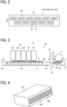
- Each of the liquid discharge units 15C, 15M, 15Y, and 15K includes, for example, a head module 20 including a full-line head as illustrated in FIG. 2 .
- the head module 20 includes a base 21 and a plurality of liquid discharge heads 22 alternately arranged on the base 21.
- the liquid discharge heads 22 each includes a plurality of nozzle rows including a plurality of nozzles 23 arrayed in a sheet width direction (lateral direction in FIG. 2 ) orthogonal to a sheet conveyance direction A.
- the drying unit 4 includes the drying device 30 that heats the sheet S to dry the ink on the sheet S.
- the drying device 30 includes a first heating unit 31 that heats the sheet S borne on the transfer cylinder 17, a second heating unit 32 that heats the sheet S again after the heating by the first heating unit 31, the upstream conveyance belt 18 as a first conveyance member to which the sheet S is transferred from the transfer cylinder 17, and a downstream conveyance belt 19 as a second conveyance member that conveys the sheet S on a downstream side in the sheet conveyance direction with respect to the upstream conveyance belt 18.
- the first heating unit 31 and the second heating unit 32 are dryers that heat the sheet S to dry the ink, and the upstream conveyance belt 18 and the downstream conveyance belt 19 form a conveyance device 10 that conveys the sheet S in the drying device 30.
- the sheet S When the sheet S is borne on the transfer cylinder 17, the sheet S is heated by the first heating unit 31. While being heated on the transfer cylinder 17, the sheet S is transferred from the transfer cylinder 17 to the upstream conveyance belt 18 at a position where the transfer cylinder 17 faces the upstream conveyance belt 18. The sheet S is further transferred from the upstream conveyance belt 18 to the downstream conveyance belt 19. When the sheet S reaches a position facing the second heating unit 32 along with the conveyance of the downstream conveyance belt 19, the sheet S is heated by the second heating unit 32. In this manner, the sheet S is heated by the first heating unit 31 and the second heating unit 32, so that the drying of the ink on the sheet S is promoted.
- the sheet reversing device 5 reverses the front side and the back side of the sheet S to convey to the image forming device 3 again in a case of duplex printing.
- the sheet reversing device 5 includes a switchback conveyor 24 that conveys the sheet S in an opposite direction by a switchback system, and a duplex conveyor 25 that conveys the switch-backed sheet S to an upstream side from the transfer cylinder 16 in the sheet conveyance direction.
- the sheet S is conveyed to the sheet reversing device 5 after a drying process in the drying unit 4, and conveyed in the opposite direction by the switchback conveyor 24.
- the sheet S is conveyed to the upstream side from the transfer cylinder 16 through the duplex conveyor 25. As a result, the sheet S is supplied to the image forming device 3 in a state of being reversed. Then, after an image is formed on the back side of the sheet S in the image forming device 3, the sheet S is conveyed from the sheet reversing device 5 to the sheet ejection device 6 through the drying process by the drying unit 4.
- the sheet S on one side or both sides of which an image is formed is ejected to the sheet ejection device 6.
- the sheet ejection device 6 includes an ejection tray 26 on which the ejected sheets S are stacked. When the sheet S is conveyed from the sheet reversing device 5 to the sheet ejection device 6, the sheets S are sequentially stacked and placed on the ejection tray 26.
- the first heating unit 31 included in the drying device 30 includes a warm air generator 33.
- the warm air generator 33 is disposed in a non-contact manner so as to face the outer peripheral surface of the transfer cylinder 17.
- the warm air generator 33 is provided with a heater that generates hot air and a nozzle that blows the generated hot air as warm air toward the transfer cylinder 17.
- the outer peripheral surface of the transfer cylinder 17 is warmed.
- the sheet S on the transfer cylinder 17 is heated, and an ink drying process is performed.
- the warm air generator 33 can adjust the temperature of the warm air in the rage from room temperature to about 100°C based on the temperature detected by a temperature detection sensor mounted thereon.
- the temperature of the warm air can be optionally set according to information such as the amount of liquid (ink) adhered to a sheet S and the type (material) of sheet. From the viewpoint of reducing waviness (cockling) of a sheet due to application of liquid such as ink, low-temperature warm air is preferably blown, for example, with the heater turned off.
- the second heating unit 32 included in the drying device 30 includes a plurality of ultraviolet irradiators 34 arranged in the sheet conveyance direction A.
- the ultraviolet irradiators 34 are arranged above the downstream conveyance belt 19 so as to face the downstream conveyance belt 19, and irradiates a sheet S conveyed by the downstream conveyance belt 19 with ultraviolet rays to heat the sheet S.
- the ultraviolet irradiator 34 includes an irradiation surface 34a on which a plurality of granular ultraviolet-light-emitting diode (UV-LED) light emitting elements 340 are arranged. Since each UV-LED light emitting element 340 emits light with the same illuminance, the irradiation surface 34a uniformly emits light as a whole.
- UV light for example, one having a peak wavelength of 395 nm and a full width at half maximum of about 15 nm as the wavelength distribution is used. However, the peak wavelength and wavelength distribution of the UV light are not limited thereto.
- the drying device 30 includes the conveyance device 10 including the upstream conveyance belt 18 and the downstream conveyance belt 19.
- the upstream conveyance belt 18 is wound and supported around a plurality of support rollers 27 in endless form.
- the upstream conveyance belt 18 rotates (circulates).
- the upstream conveyance belt 18 is supported by the two support rollers 27 in the present embodiment, in some embodiments, the number of support rollers 27 supporting the upstream conveyance belt 18 may be two or more.
- a mesh belt or a plain-woven belt provided with a large number of holes on a conveyance surface (outer peripheral surface) 18a that holds the sheet S is used.
- the term "conveyance surface” as used herein means a portion forming a planar conveyance path, on which a sheet being an object to be conveyed is held or placed. The portion contacting the sheet is not necessarily a surface, and may be, for example, a mesh.
- a suction chamber 35 including a blower or a fan as a suction device is arranged inside the upstream conveyance belt 18.
- the suction chamber 35 is driven and air is sucked from a large number of holes on the conveyance surface 18a of the upstream conveyance belt 18, the sheet S is attracted to the conveyance surface 18a by the sucked air.
- the upstream conveyance belt 18 rotates in a state in which the sheet S is attracted, so that the sheet S is conveyed downstream.
- the downstream conveyance belt 19 arranged downstream from the upstream conveyance belt 18 in the sheet conveyance direction is basically configured in the same manner as the upstream conveyance belt 18.
- the downstream conveyance belt 19 is endlessly wound around a plurality of support rollers 28, and at least one of the support rollers 28 functions as a drive roller to rotate (circulate).
- the downstream conveyance belt 19 is supported by the two support rollers 28.
- the number of support rollers 28 supporting the downstream conveyance belt 19 may be two or more.
- a suction chamber 36 is disposed inside the loop of the downstream conveyance belt 19.
- the suction chamber 36 When the suction chamber 36 is driven and air is sucked from a large number of holes on a conveyance surface 19a of the downstream conveyance belt 19, the sheet S is attracted to the conveyance surface 19a by the sucked air.
- the downstream conveyance belt 19 rotates with the sheet S attracted on the conveyance surface 19a, the sheet S is conveyed downstream.
- a mechanism for attracting the sheet S to the upstream conveyance belt 18 and the downstream conveyance belt 19 is not limited to the mechanism using the airflow as described above, and may be an electrostatic attraction mechanism for attracting the sheet to the belt using static electricity.
- a grip unit such as a gripper may be disposed on each of the conveyance belts 18 and 19, and the sheet may be gripped by the grip unit.
- a guide 29 is arranged between the upstream conveyance belt 18 and the downstream conveyance belt 19. That is, the conveyance device 10 according to the present embodiment includes the guide 29 that guides the sheet S from the upstream conveyance belt 18 to the downstream conveyance belt 19 in addition to the upstream conveyance belt 18 and the downstream conveyance belt 19. The guide 29 is arranged close to the conveyance surfaces 18a and 19a of the upstream conveyance belt 18 and the downstream conveyance belt 19, respectively, so as not to come into contact with them.
- the drying device 30 configured as described above operates as follows.
- the heat of the transfer cylinder 17 heated by the warm air generator 33 to the sheet S is applied to the sheet S and the sheet S is heated.
- the drying of the ink on the sheet S is promoted, and a first drying process is performed on the sheet S.
- the sheet S is transferred to the upstream conveyance belt 18 while being heated on the transfer cylinder 17, and is conveyed by the upstream conveyance belt 18.
- the sheet S is guided to the downstream conveyance belt 19 via the guide 29, and is conveyed by the downstream conveyance belt 19.
- each ultraviolet irradiator 34 irradiates the sheet S with ultraviolet rays to heat the sheet S. Therefore, a second drying process is performed on the sheet S.
- the drying device 30 after the first drying process of heating the sheet S by the heat of the transfer cylinder 17 heated by the warm air generator 33 is performed, the second drying process of heating the sheet S by the ultraviolet rays from each ultraviolet irradiator 34 is performed.
- the ink on the sheet S can be effectively dried.
- the ultraviolet irradiator 34 is used as a heating device for performing the second drying process, only an image portion (portion to which the ink is applied) of the sheet S can be selectively heated. As a result, the temperature of a non-image portion (portion to which no ink is applied) of the sheet S does not rise more than necessary, and excessive evaporation of moisture contained in the non-image portion can be reduced, so that waviness of the sheet S can be reduced.
- an infrared irradiator for emitting infrared rays to heat an object such as an IR lamp may be used, but the ultraviolet irradiator is more preferable than the infrared irradiator from the viewpoint of appropriately maintaining the moisture amount of the sheet after the drying process.
- the ultraviolet irradiator is more preferable than the infrared irradiator from the viewpoint of appropriately maintaining the moisture amount of the sheet after the drying process.
- the water content of the non-image portion decreased from 6.1% to 1.4% in the case of using the infrared irradiator, whereas the water content of the non-image portion merely decreased from 6.1% to 2.9% in the case of using the ultraviolet irradiator. That is, it was confirmed that the moisture content of the non-image portion can be kept high in the case of using the ultraviolet irradiator as compared with the case of using the infrared irradiator. From this result also, it can be said that the ultraviolet irradiator is more preferable than the infrared irradiator in order to appropriately maintain the moisture amount of the sheet after the drying process.
- a belt endlessly wound around a plurality of support rollers is used as the upstream conveyance belt 18 and the downstream conveyance belt 19.
- a belt including a j oint in a part in the rotation direction can be used.
- the type that can be separated at a joint portion has an advantage that the belt can be easily removed at the time of replacement work or maintenance work of the belt and other components. Therefore, in the present embodiment, a separable belt including the joint in a part in the rotation direction is used as the upstream conveyance belt 18 and the downstream conveyance belt 19.
- both ends 90b and 90c of the belt 90 are connected using a connecting member 91 such as a pin to make the belt 90 endless.
- the belt 90 can be easily attached by connecting both ends 90b and 90c of the belt 90 after winding the belt 90 around a plurality of support rollers, and conversely, the belt 90 can be easily detached by releasing the connection between both ends 90b and 90c.
- a case where a mesh-shaped belt is used is taken as an example, but a flat belt may be used.
- a material of the belt a material having heat resistance such as a fluorine-based material or a silicone-based material is preferable.
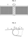
- FIG. 6 is a diagram illustrating a positional relationship between the belt 90 including a joint J and a guide 80 arranged close to the belt 90.
- the guide 80 illustrated in FIG. 6 is a member for receiving an object conveyed by the belt 90 and guiding the object to the downstream side. Therefore, a leading end 80a of the guide 80 is arranged close to a conveyance surface (outer peripheral surface) 90a of the belt 90 so that the object to be conveyed can be favorably received from the belt 90.
- the object to be conveyed is a thin member such as a sheet
- the belt 90 including the joint J since a connecting member 91 connecting both ends of the belt 90 is inserted at the joint J, a portion of the joint J protrudes in a direction perpendicular to the conveyance surface 90a (toward the outer peripheral surface of the belt 90) than any other portion. Therefore, the guide 80 needs to be arranged with a large distance D with respect to the conveyance surface 90a secured so as not to interfere with the portion of the joint J. Therefore, the belt including the joint has a problem of difficulty in reducing the distance between the leading end of the guide and the conveyance surface of the belt as compared with a seamless belt including no joint.
- the guide has the following configuration so that the distance between the surface of the conveyance belt and the leading end of the guide can be reduced even with the conveyance belt including the joint.
- a configuration of the guide according to an embodiment of the present disclosure will be described in detail.
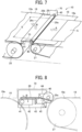
- FIG. 7 is a perspective view illustrating a configuration of a guide 29 included in the conveyance device 10 according to the present embodiment and a peripheral portion thereof.
- the guide 29 is formed of a plate member extending in a width direction of the upstream conveyance belt 18 or the downstream conveyance belt 19.
- the guide 29 includes a guide surface 29b arranged substantially flush with the conveyance surface 18a of the upstream conveyance belt 18 and the conveyance surface 19a of the downstream conveyance belt 19 (upper surfaces of the conveyance belts 18 and 19 in FIG. 7 ), and the sheet S is guided from the upstream conveyance belt 18 to the downstream conveyance belt 19 along the guide surface 29b.
- the "width direction of the upstream conveyance belt 18 or the downstream conveyance belt 19" means a direction orthogonal to the sheet conveyance direction A along the conveyance surface of the conveyance belt.
- a direction in which the guide 29 extends in the width direction of the conveyance belt is referred to as a "longitudinal direction" of the guide 29 in the following description.
- the width of the guide 29 in the longitudinal direction is set to be equal to or larger than the width of a conveyance region E in which the sheet S is conveyed and equal to or smaller than each of the width of the upstream conveyance belt 18 and the width of the downstream conveyance belt 19.
- a commonly-used material can be applied as long as the sliding resistance with respect to the sheet S is small.
- the material used for the guide 29 include, but not limited to, stainless used steel (SUS), an electrogalvanized steel sheet such as silver top, and an uneven steel sheet.
- ribs may be disposed on the guide 29.
- the material of the guide 29 is preferably the same as that of the upstream conveyance belt 18 or the downstream conveyance belt 19.
- the surface roughness and the hardness of the guide 29 are substantially the same as those of the upstream conveyance belt 18 or the downstream conveyance belt 19.
- a pair of frame members 70 that supports the conveyance belts 18 and 19, and the support rollers 27 and 28 in addition to the guide 29 is disposed on both ends in the longitudinal direction of the guide 29.
- the guide 29 is attached to each frame member 70 so as to be swingable in a direction of an arrow B in FIG. 7 .
- the guide 29 is rotatably supported around a support shaft 41 arranged on a rear end 29c side of the guide 29.
- the leading end 29a (end on a side opposite to the rear end 29c) of the guide 29 is configured to be swingable in a direction to approach and a direction to move away from the conveyance surface 18a of the upstream conveyance belt 18.
- a pair of rotators 40 in contact with the conveyance surface 18a of the upstream conveyance belt 18 is disposed at both ends in the longitudinal direction of the guide 29.
- Each rotator 40 is arranged outside a conveyance region E where the sheet S is conveyed so as not to come into contact with the sheet S to be conveyed.
- the leading end 29a of the guide 29 is arranged to approach (so as not to be in contact with) the conveyance surface 18a of the upstream conveyance belt 18.
- FIG. 8 is a cross-sectional view of the guide 29 as seen in the longitudinal direction thereof.
- the guide 29 is attached to and held by a movable stay 42, which is a guide holding member.
- the movable stay 42 includes the support shaft 41, which is the swing center of the guide 29, and when the movable stay 42 rotates about the support shaft 41, the guide 29, together with the movable stay 42, swings in a direction intersecting the conveyance surface 18a of the upstream conveyance belt 18 (direction of arrow B in FIG. 8 ).
- the movable stay 42 is rotatably attached to a fixed stay 43 as a supporting member via the support shaft 41.
- the support shaft 41 is attached to the fixed stay 43 so as to be movable in the axial direction (so as to have a backlash) so that even if the guide 29 and the movable stay 42 thermally expand in the longitudinal direction by the heat of the drying device 30, the support shaft 41 does not interfere with the fixed stay 43 to limit the swing of the guide 29 or damage the members.
- the fixed stay 43 is fixed so as not to be movable with respect to the frame member 70.
- a rotator holding member 44 that rotatably holds the rotator 40 is attached to the movable stay 42.
- the rotator 40 is arranged so as to protrude toward the upstream conveyance belt 18 beyond the leading end 29a of the guide 29. Therefore, in a state in which the rotator 40 is in contact with the conveyance surface 18a of the upstream conveyance belt 18, the leading end 29a of the guide 29 is arranged so as not to be in contact with the conveyance surface 18a.
- a spring 45 as a biasing member is attached between the rotator holding member 44 and the fixed stay 43.
- the spring 45 is provided to bias the rotator 40 toward the upstream conveyance belt 18.
- the rotator 40 is held in a state of being in contact with the conveyance surface 18a of the upstream conveyance belt 18.
- FIG. 9 is a plan view illustrating a configuration of one end side in the longitudinal direction of the guide 29.
- a hole 29d into which a fixing member 46 such as a screw is inserted is disposed on one end side in the longitudinal direction of the guide 29.
- the hole 29d is also disposed on an opposite end side (the other end side in the longitudinal direction) of the one end side in the longitudinal direction of the guide 29 illustrated in FIG. 9 .
- the hole 29d is formed of a long hole extending along the guide surface 29b in a direction (vertical direction in FIG. 9 ) intersecting the longitudinal direction of the guide 29. Therefore, when the guide 29 is moved in a direction in which the hole 29d extends, a fixing position of the guide 29 can be changed to an upward direction or a downward direction in FIG. 9 . That is, the guide 29 can be moved in the direction to approach and the direction to move away from the conveyance surface 18a of the upstream conveyance belt 18. Accordingly, it is possible to adjust the distance D between the leading end 29a of the guide 29 and the conveyance surface 18a.
- FIGS. 10 and 11 the downstream conveyance belt 19 is not illustrated.
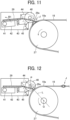
- the rotator 40 in a state in which the leading end 29a of the guide 29 is arranged so as to approach the conveyance surface 18a of the upstream conveyance belt 18, the rotator 40 is held in a state of being in contact with the conveyance surface 18a by a biasing force of the spring 45.
- the rotator 40 also rotates accordingly.
- the rotator 40 is a circular rotator having a constant distance from a rotation center P to the outer peripheral surface, even when the rotator 40 rotates, a distance between the leading end 29a of the guide 29 and the conveyance surface 18a of the upstream conveyance belt 18 is maintained constant.
- the distance between the leading end 29a of the guide 29 and an outer peripheral surface of the support roller 27 increases, and a distance necessary for the joint J to pass is secured, so that the portion of the joint J can be avoided from coming into contact with the leading end 29a of the guide 29.
- the distance between the leading end 29a of the guide 29 and the portion of the joint J may be larger than or the same as the distance between the leading end 29a of the guide 29 and the conveyance surface 18a in the portion other than the joint J. In short, it is sufficient that the guide 29 can swing in such a manner that the leading end 29a of the guide 29 can avoid the contact with the portion of the joint J.
- the guide 29 is displaced (swung) in conjunction with the displacement of the rotator 40 due to the contact between the portion of the joint J and the rotator 40, so that the contact of the guide 29 with the portion of the joint J can be avoided.
- the guide 29 since the guide 29 is configured to swing about the support shaft 41 to approach and move away from the conveyance surface 18a, displacement of the rear end 29c side of the guide 29 can be reduced as compared with a configuration in which the guide 29 linearly slides to approach and move away from the conveyance surface 18a. Therefore, in the present embodiment, the guide 29 (rear end 29c) can be arranged close to the conveyance surface 19a of the downstream conveyance belt 19, and the sheet can be smoothly and reliably transferred between the guide 29 and the downstream conveyance belt 19.
- the present disclosure does not exclude a configuration in which the guide linearly slides to approach and move away from the conveyance surface of the conveyance belt.
- the guide 29 is arranged between the upstream conveyance belt 18 and the downstream conveyance belt 19 and it is difficult to secure a space for linearly moving the guide 29 as in the present embodiment, it is preferable to adopt the configuration in which the guide is swung.
- the position of the leading end 29a of the guide 29 is preferably set on a straight line L passing through a rotation center Q of the support roller 27 (specifically, the support roller 27 which the rotator 40 faces via the upstream conveyance belt 18) and the rotation center P of the rotator 40.
- the leading end 29a of the guide 29 can be greatly swung (retracted) in accordance with a timing at which the portion of the joint J reaches the position of the leading end 29a of the guide 29, so that interference between the leading end 29a of the guide 29 and the portion of the joint J can be more reliably avoided.
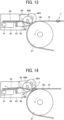
- a plurality of rotators 40A and 40B may be arranged side by side in the sheet conveyance direction.
- the two rotators 40A and 40B are arranged at the position of the leading end 29a of the guide 29 and a position on the upstream side of the leading end in the sheet conveyance direction.
- the guide 29 swings in the direction away from the conveyance surface 18a in conjunction with the displacement of the rotator 40A due to the contact. Subsequently, as illustrated in FIG.
- the portion of the joint J comes into contact with a second rotator 40B (downstream side), so that the guide 29 is held in a state of being swung in the direction away from the conveyance surface 18a. That is, before the portion (protrusion) of the joint J completely passes through the contact position with the first rotator 40A, the portion of the joint J comes into contact with the second rotator 40B, so that the guide 29 is held in a swinging state. Therefore, in this case, the guide 29 is held in a state of being swung in the direction away from the conveyance surface 18a until the portion of the joint J passes through the second rotator 40B after coming into contact with the first rotator 40A.
- the guide 29 can be continuously retracted from a stage earlier than the reach of the portion of the joint J, so that the contact between the guide 29 and the portion of the joint J can be more reliably avoided.
- the number of rotators arranged in the sheet conveyance direction is not limited to two, and may be three or more.
- the rotators may be arranged not only at a position on the upstream side in the sheet conveyance direction with respect to the position of the leading end 29a of the guide 29 but also at a position on the downstream side.
- the position of the leading end 29a of the guide 29 is preferably set on the straight line L passing the rotation center P of any one of the rotators and the rotation center Q of the support roller 27 when viewed from the axial direction of the support roller 27, as in the embodiment of FIG. 12 .
- the rotation center P of any one of the rotators is preferably disposed on the straight line L passing the leading end 29a of the guide 29 and the rotation center Q of the support roller 27 when viewed from the axial direction of the support roller 27.
- leading end 29a of the guide 29 can be greatly swung (retracted) in accordance with a point in time at which the portion of the joint J reaches the position of the leading end 29a of the guide 29, so that interference between the leading end 29a of the guide 29 and the portion of the joint J can be more reliably avoided.
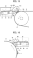
- the configuration in which the leading end 29a of the guide 29 swings in the direction to approach and the direction to move away from the conveyance surface 18a of the upstream conveyance belt 18 is taken as an example, but as in the example illustrated in FIG. 16 , the leading end 29a of the guide 29 may be arranged to approach the conveyance surface 19a of the downstream conveyance belt 19.
- the leading end 29a of the guide 29 swings in the direction away from the conveyance surface 19a as in the above-described embodiment, so that the interference between the leading end 29a of the guide 29 and the joint portion can be avoided.
- Embodiments of the present disclosure are not limited to the configuration using the conveyance belt in which the joint portion protrudes as described above, and are also applicable to a configuration using a conveyance belt in which the joint portion is recessed in a concave shape as compared with other portions.
- the distance between the guide and the conveyance belt increases at the joint portion as opposed to the case where the joint portion has a convex shape, so that there is a possibility that a disadvantage might occur that the sheet enters between the guide and the conveyance belt.
- entry of the sheet at the joint portion can be reduced.
- the guide is displaced in the direction to approach the conveyance surface in accordance with the shape of the joint portion, so that the distance between the guide and the conveyance belt at the joint portion can be reduced, and the entry of the sheet between the guide and the conveyance belt can be reduced.
- the present disclosure is also applicable to the following drying device.
- a configuration of the drying device according to another embodiment of the present disclosure will be described.
- the first heating unit 31 includes an infrared irradiator 37 in addition to the warm air generator 33. Except for this, the drying device has the same configuration as the drying device according to the above-described embodiment (refer to FIG. 3 ).
- the sheet S when the sheet S is borne on the transfer cylinder 17, the sheet S is heated by the heat of the warm air generator 33 and is heated by the infrared rays emitted from the infrared irradiator 37.
- the drying of the ink on the sheet S can be promoted as compared with the drying device according to the above-described embodiment.
- a blower fan 38 as a cooling device is disposed at a position facing the upstream conveyance belt 18. Air is blown from the blower fan 38 to the upstream conveyance belt 18 to cool the upstream conveyance belt 18, so that a temperature rise of the upstream conveyance belt 18 is reduced.
- the temperature rise of the sheet S conveyed by the upstream conveyance belt 18 is also reduced, the occurrence of waviness of the sheet S can also be reduced in addition to density unevenness due to movement of pigment of the ink.
- the second heating unit 32 includes a heating element 39 that heats the downstream conveyance belt 19 in addition to a plurality of ultraviolet irradiators 34.
- the heating element 39 is, for example, an infrared heater (IR lamp), and is arranged in the support roller 27 on the upstream side that supports the downstream conveyance belt 19. When the heating element 39 generates heat, the downstream conveyance belt 19 is heated via the support roller 27.
- IR lamp infrared heater
- the sheet S is held on the downstream conveyance belt 19, the sheet S is heated by the heat of the heated downstream conveyance belt 19. Furthermore, since the sheet S is irradiated by each ultraviolet irradiator 34 with ultraviolet rays, drying of the ink on the sheet S is effectively promoted. Except for the configuration described above, the configuration is the same as that of the drying device illustrated in FIG. 17 , so that the description thereof is omitted.
- the “liquid discharge apparatus” means an apparatus that includes a liquid discharger and drives the liquid discharger to discharge liquid onto a sheet. Therefore, the “liquid discharge apparatus” is not limited to one that visualizes a meaningful image such as a character or a figure by the discharged liquid. Examples of the “liquid discharge apparatus” include an apparatus that forms a pattern having no meaning in itself, an apparatus that forms a three-dimensional image, and a treatment liquid discharge apparatus that discharges a treatment liquid onto a surface of a sheet for the purpose of modifying the surface of the sheet.
- the "liquid discharge apparatus" to which the conveyance device according to the present disclosure is applied may include devices to feed, convey, and eject the sheet, a pretreatment device, and a post-processing device.
- the liquid discharger may move relative to the sheet, or the liquid discharger is not necessarily move relative to the sheet.
- Specific examples of the “liquid discharge apparatus” include a serial type apparatus that moves the liquid discharge head (liquid discharger) or a line type apparatus that does not move the liquid discharge head (liquid discharger).
- the above-described "sheet” represents a sheet on which liquid can be at least temporarily adhered, and includes a sheet on which liquid is adhered and fixed, or a sheet to which liquid is adhered to permeate. Specific examples thereof include a recording medium such as paper, recording paper, a recording sheet, a film, and cloth, and an electronic substrate.
- the "sheet” may be a long sheet (roll paper) wound in a roll shape in addition to a sheet (cut paper) cut into a predetermined size in the sheet conveyance direction in advance.
- Examples of the material of the "sheet” include any material on which liquid can be adhered even temporarily, such as paper, thread, fiber, fabric, leather, metal, plastic, glass, wood, and ceramic.
- Liquid discharged by the “liquid discharge apparatus” is not limited to a particular liquid as long as the liquid has a viscosity or surface tension dischargeable from the liquid discharger.
- the viscosity of the liquid is not greater than 30 mPa s under ordinary temperature and ordinary pressure or by heating or cooling. More specific examples thereof include solutions, suspensions, and emulsions containing solvents such as water and organic solvents, colorants such as dyes and pigments, function-imparting materials such as polymerizable compounds, resins, and surfactants, biocompatible materials such as deoxyribonucleic acid (DNA), amino acids, proteins, and calcium, and edible materials such as natural pigments. These can be used for, for example, inkjet ink, surface treatment liquid, electronic element, constituent parts of light emitting element, liquid for forming electronic circuit resist pattern, and material liquid for three-dimensional modeling.
- the conveyance device is not limited to a device mounted on a liquid discharge apparatus such as an inkjet image forming apparatus.
- a conveyance device mounted on an electrophotographic image forming apparatus that forms an image using toner
- a conveyance device mounted on a belt conveyor that conveys an object other than a sheet.
- embodiments of the present disclosure include a conveyance device, a drying device, an image forming apparatus, and a liquid discharge apparatus having at least the following configurations.
- a conveyance device includes: a conveyance member having a conveyance surface with a joint, to convey the object with the object held or placed on the conveyance surface; a guide arranged to approach the conveyance surface and guide the object from or to the conveyance member; and a rotator to contacts the conveyance surface.
- the guide displaces in a direction perpendicular to the conveyance surface, in conjunction with displacement of the rotator when the rotator contacts the joint.
- the joint in the conveyance device according to the first aspect, includes a protruding portion protruding from the conveyance surface, and the guide displaces in a direction away from the conveyance surface in conjunction with displacement of the rotator when the rotator contacts the protruding portion.
- the guide is swingable about a support shaft and displaceable with respect to the conveyance surface.
- the conveyance member is a conveyance belt wound around a support roller, and a leading end of the guide having approached a position close to the conveyance belt is placed on a straight line passing a rotation center of the support roller and a rotation center of the rotator.
- the conveyance device includes a plurality of rotators, including the rotator, arranged side by side in a conveyance direction in which the conveyance member conveys the object to be conveyed.
- the conveyance member includes a first conveyance member and a second conveyance member arranged on a downstream side of the first conveyance member in a conveyance direction in which the conveyance member conveys the object, and the guide guides the object from the first conveyance member to the second conveyance member between the first conveyance member and the second conveyance member.
- the first conveyance member conveys the object subjected to a first drying process
- the second conveyance member conveys the object subjected to a second drying process
- a drying device includes: the conveyance device according to any one of the first to seventh aspects to convey the object to be conveyed; and a dryer to dry the object.
- an image forming apparatus includes: an image forming device to form an image on a sheet; and the conveyance device according to any one of the first to seventh aspects to convey the sheet.
- a liquid discharge apparatus includes a liquid discharger to discharge liquid onto a sheet; and the conveyance device according to any one of the first to seventh aspects to convey the sheet.
- Processing circuitry includes a programmed processor, as a processor includes circuitry.
- a processing circuit also includes devices such as an application specific integrated circuit (ASIC), digital signal processor (DSP), field programmable gate array (FPGA), and conventional circuit components arranged to perform the recited functions.
- ASIC application specific integrated circuit
- DSP digital signal processor
- FPGA field programmable gate array
Abstract
A conveyance device (10) includes a conveyance member (18, 19), a guide (29), and a rotator (40A, 40B). The conveyance member (18, 19) has a conveyance surface with a joint, the conveyance member (18, 19) to convey an object to be conveyed, with the object on the conveyance surface. The guide (29) approaches the conveyance surface and guides the object from or to the conveyance member. The rotator (40A, 40B) contacts the conveyance surface (18a). The guide (29) displaces in a direction perpendicular to the conveyance surface, in conjunction with displacement of the rotator when the rotator contacts the joint.
Description
- Embodiments of the present disclosure relate to a conveyance device, a drying device, an image forming apparatus, and a liquid discharge apparatus.
- In an image forming apparatus such as a copier or a printer, a conveyance device that conveys a sheet is provided.
- As such a conveyance device, there is a conveyance device that includes a conveyance belt to support a sheet on a surface thereof and convey the sheet and a guide to guide the sheet from or to the conveyance belt (see, for example,
Japanese Unexamined Patent Application Publication No. 2014-102286 - Typically, a leading end of the guide is arranged in a non-contact manner with respect to the surface of the conveyance belt. However, when the distance between the leading end of the guide and the surface of the conveyance belt is excessively increased, there is a possibility that the sheet cannot be satisfactorily transferred between the guide and the conveyance belt. For this reason, the distance between the leading end of the guide and the surface of the conveyance belt is appropriately managed.
- There is an endless conveyance belt that is wound around a plurality of support rollers and is endlessly formed by connecting both ends of a band-shaped belt so as to facilitate replacement work or maintenance work of components. In the case of such a conveyance belt, since there is a joint, the shape of the conveyance belt is non-uniform at a joint portion.
- For example, in the case where the belt surface protrudes at the joint portion, the distance between the leading end of the guide and the belt surface to be large is set so that the leading end of the guide does not interfere with the protruding joint portion. However, in this case, since the distance between the guide and the conveyance belt becomes large particularly at a portion other than the j oint, there is a possibility that the sheet enters between the guide and the conveyance belt, causing a paper jam or conveyance failure. In contrast, when the joint portion has a concave shape, the distance between the guide and the conveyance belt increases at the joint portion, so that the sheet might enter between the guide and the conveyance belt.
- It is therefore an object of the present disclosure to reduce the distance between the surface of a conveyance member and the leading end of a guide even when the conveyance member is, for example, a conveyance belt having a joint.
- In order to solve the above-described problem, according to an embodiment of the present disclosure, a conveyance device includes a conveyance member, a guide, and a rotator. The conveyance member has a conveyance surface with a joint, the conveyance member to convey an object to be conveyed, with the object on the conveyance surface. The guide approaches the conveyance surface and guide the object from or to the conveyance member. The rotator contacts the conveyance surface. The guide displaces in a direction perpendicular to the conveyance surface, in conjunction with displacement of the rotator when the rotator contacts the joint.
- According to another embodiment of the present disclosure, a drying device includes the conveyance device to convey the object to be conveyed and a dryer to dry the object to be conveyed.
- According to still another embodiment of the present disclosure, an image forming apparatus includes an image forming device to form an image on a sheet and the conveyance device to convey the sheet.
- According to still yet another embodiment of the present disclosure, a liquid discharge apparatus includes a liquid discharger to discharge liquid onto a sheet and the conveyance device to convey the sheet.
- According to at least one embodiment of the present disclosure, even with the conveyance member including the joint, the distance between the surface of the conveyance member and the leading end of the guide can be reduced.
- A more complete appreciation of embodiments of the present disclosure and many of the attendant advantages and features thereof can be readily obtained and understood from the following detailed description with reference to the accompanying drawings, wherein:
-
FIG. 1 is a schematic diagram illustrating a configuration of an inkjet image forming apparatus according to an embodiment of the present disclosure; -
FIG. 2 is a plan view of a liquid discharge unit according to an embodiment of to the present disclosure; -
FIG. 3 is a diagram illustrating a general arrangement of a drying device according to an embodiment of to the present disclosure; -
FIG. 4 is a perspective view of an ultraviolet irradiator according to an embodiment of the present disclosure; -
FIG. 5 is a plan view of a conveyance belt according to an embodiment of the present disclosure, illustrating a joint portion of the conveyance belt; -
FIG. 6 is a diagram illustrating a positional relationship between a belt including a joint and a guide arranged close to the belt; -
FIG. 7 is a perspective view of a guide and a peripheral portion thereof included in a drying device according to an embodiment of the present disclosure; -
FIG. 8 is a cross-sectional view of the guide ofFIG. 7 as seen in a longitudinal direction thereof; -
FIG. 9 is a plan view of the guide ofFIG. 7 , illustrating a configuration of one end in a longitudinal direction of the guide; -
FIG. 10 is a diagram illustrating a rotator contacting a portion other than a joint; -
FIG. 11 is a diagram illustrating the rotator contacting a joint portion; -
FIG. 12 is a diagram illustrating a preferred position of a leading end of a guide; -
FIG. 13 is a diagram illustrating a guide according to a modification of the present disclosure; -
FIG. 14 is a diagram illustrating a joint portion contacting a first rotator; -
FIG. 15 is a diagram illustrating the joint portion contacting a second rotator; -
FIG. 16 is a diagram illustrating an example in which a leading end of a guide approaches and moves away from a downstream conveyance belt; -
FIG. 17 is a diagram illustrating a configuration of a drying device according to another embodiment of the present disclosure; and -
FIG. 18 is a diagram illustrating a configuration of a drying device according to still another embodiment of the present disclosure. - The accompanying drawings are intended to depict embodiments of the present disclosure and should not be interpreted to limit the scope thereof. The accompanying drawings are not to be considered as drawn to scale unless explicitly noted. Also, identical or similar reference numerals designate identical or similar components throughout the several views.
- In describing embodiments illustrated in the drawings, specific terminology is employed for the sake of clarity. However, the disclosure of this specification is not intended to be limited to the specific terminology so selected and it is to be understood that each specific element includes all technical equivalents that have a similar function, operate in a similar manner, and achieve a similar result.
- Referring now to the drawings, embodiments of the present disclosure are described below. As used herein, the singular forms "a," "an," and "the" are intended to include the plural forms as well, unless the context clearly indicates otherwise.
- With reference to drawings, embodiments of the present disclosure are described in detail below. Note that identical reference numerals are assigned to identical components or equivalents and a redundant description of those components is appropriately simplified or omitted.
- Hereinafter, an embodiment of the present disclosure will be described taking an example of a conveyance device mounted on an inkjet image forming apparatus. In the drawings for describing embodiments of the present disclosure, components such as members and constituent parts having the same function or shape are denoted by the same reference numerals as far as discriminable, and the description thereof will be omitted after once described.
- First, a general arrangement of an inkjet image forming apparatus according to the present embodiment will be described with reference to
FIG. 1 . - An inkjet
image forming apparatus 100 illustrated inFIG. 1 includes asheet supply device 1, apretreatment device 2, animage forming device 3, adrying unit 4, asheet reversing device 5, and asheet ejection device 6. - The
sheet supply device 1 supplies a sheet as a recording medium on which an image is formed, and includes asupply tray 11 to accommodate a plurality of sheets S, and afeeder 12 that separates and feeds the sheets S one by one from thesupply tray 11. The sheet S fed by thefeeder 12 is supplied to thepretreatment device 2. - The
pretreatment device 2 applies a treatment liquid to the sheet S supplied from thesheet supply device 1, and includes a treatment liquid applier 13 that applies the treatment liquid. The treatment liquid is, for example, a liquid having a function of aggregating ink, and is applied to the sheet S before image formation by the treatment liquid applier 13 for the purpose of enhancing an image quality such as preventing ink bleeding and assisting ink permeation. The sheet S to which the treatment liquid is applied is supplied to theimage forming device 3. - The
image forming device 3 forms an image on the supplied sheet S. Specifically, theimage forming device 3 includes adrum 14 as a first bearing rotator that rotates while bearing the sheet S on an outer peripheral surface thereof, a plurality ofliquid discharge units drum 14, atransfer cylinder 16 as a second bearing rotator that transfers the sheet S supplied from thepretreatment device 2 to thedrum 14, and atransfer cylinder 17 as a third bearing rotator that transfers the sheet S from thedrum 14 to anupstream conveyance belt 18 included in adrying device 30 described later. In the example illustrated inFIG. 1 , theliquid discharge unit 15C for cyan ink, theliquid discharge unit 15M for magenta ink, theliquid discharge unit 15Y for yellow ink, and theliquid discharge unit 15K for black ink are arranged in this order from an upstream side in a rotation direction of the drum 14 (conveyance direction of the sheet S). The arrangement of theliquid discharge units FIG. 1 , and may be in any other order. A liquid discharge unit that discharges ink of a special color such as white, gold, and silver may be added as necessary. - When the sheet S is supplied from the
pretreatment device 2 to theimage forming device 3, a leading end of the sheet S is gripped by a sheet gripper as a gripper included in thetransfer cylinder 16, and the sheet S is conveyed with the rotation of thetransfer cylinder 16. The sheet S is transferred to thedrum 14 at a position where thetransfer cylinder 16 and thedrum 14 face each other. A sheet gripper as a gripper is disposed on the outer peripheral surface of thedrum 14 in the same manner as thetransfer cylinder 16, and the leading end of the sheet S is gripped by the sheet gripper. A plurality of suction holes are dispersedly formed on the outer peripheral surface of thedrum 14, and airs flow sucked into thedrum 14 from suction holes can be generated by a suction device. As a result, the sheet S is attracted by the outer peripheral surface of thedrum 14 to be borne thereon. The sheet S is conveyed with the rotation of thedrum 14 while being borne on the outer peripheral surface of thedrum 14 by an attracting action of the sheet gripper and the air flow. - Then, when the sheet S on the
drum 14 is conveyed to a position facing each of theliquid discharge units liquid discharge units liquid discharge units head module 20 including a full-line head as illustrated inFIG. 2 . Specifically, thehead module 20 includes abase 21 and a plurality of liquid discharge heads 22 alternately arranged on thebase 21. The liquid discharge heads 22 each includes a plurality of nozzle rows including a plurality ofnozzles 23 arrayed in a sheet width direction (lateral direction inFIG. 2 ) orthogonal to a sheet conveyance direction A. - As illustrated in
FIG. 1 , when the sheet S is conveyed to a position facing each of theliquid discharge units liquid discharge units liquid discharge units drum 14 to thetransfer cylinder 17, and then transferred from thetransfer cylinder 17 to theupstream conveyance belt 18. - The drying
unit 4 includes the dryingdevice 30 that heats the sheet S to dry the ink on the sheet S. The dryingdevice 30 includes afirst heating unit 31 that heats the sheet S borne on thetransfer cylinder 17, asecond heating unit 32 that heats the sheet S again after the heating by thefirst heating unit 31, theupstream conveyance belt 18 as a first conveyance member to which the sheet S is transferred from thetransfer cylinder 17, and adownstream conveyance belt 19 as a second conveyance member that conveys the sheet S on a downstream side in the sheet conveyance direction with respect to theupstream conveyance belt 18. Thefirst heating unit 31 and thesecond heating unit 32 are dryers that heat the sheet S to dry the ink, and theupstream conveyance belt 18 and thedownstream conveyance belt 19 form aconveyance device 10 that conveys the sheet S in the dryingdevice 30. - When the sheet S is borne on the
transfer cylinder 17, the sheet S is heated by thefirst heating unit 31. While being heated on thetransfer cylinder 17, the sheet S is transferred from thetransfer cylinder 17 to theupstream conveyance belt 18 at a position where thetransfer cylinder 17 faces theupstream conveyance belt 18. The sheet S is further transferred from theupstream conveyance belt 18 to thedownstream conveyance belt 19. When the sheet S reaches a position facing thesecond heating unit 32 along with the conveyance of thedownstream conveyance belt 19, the sheet S is heated by thesecond heating unit 32. In this manner, the sheet S is heated by thefirst heating unit 31 and thesecond heating unit 32, so that the drying of the ink on the sheet S is promoted. - The
sheet reversing device 5 reverses the front side and the back side of the sheet S to convey to theimage forming device 3 again in a case of duplex printing. Specifically, thesheet reversing device 5 includes aswitchback conveyor 24 that conveys the sheet S in an opposite direction by a switchback system, and aduplex conveyor 25 that conveys the switch-backed sheet S to an upstream side from thetransfer cylinder 16 in the sheet conveyance direction. In the case of forming images on both sides of the sheet S, after an image is formed on the front side of the sheet S in theimage forming device 3, the sheet S is conveyed to thesheet reversing device 5 after a drying process in thedrying unit 4, and conveyed in the opposite direction by theswitchback conveyor 24. The sheet S is conveyed to the upstream side from thetransfer cylinder 16 through theduplex conveyor 25. As a result, the sheet S is supplied to theimage forming device 3 in a state of being reversed. Then, after an image is formed on the back side of the sheet S in theimage forming device 3, the sheet S is conveyed from thesheet reversing device 5 to thesheet ejection device 6 through the drying process by the dryingunit 4. - The sheet S on one side or both sides of which an image is formed is ejected to the
sheet ejection device 6. Thesheet ejection device 6 includes anejection tray 26 on which the ejected sheets S are stacked. When the sheet S is conveyed from thesheet reversing device 5 to thesheet ejection device 6, the sheets S are sequentially stacked and placed on theejection tray 26. - An overall configuration of the drying
device 30 according to the present embodiment is described below with reference toFIG. 3 . - As illustrated in
FIG. 3 , thefirst heating unit 31 included in the dryingdevice 30 includes awarm air generator 33. Thewarm air generator 33 is disposed in a non-contact manner so as to face the outer peripheral surface of thetransfer cylinder 17. Thewarm air generator 33 is provided with a heater that generates hot air and a nozzle that blows the generated hot air as warm air toward thetransfer cylinder 17. By the warm air blown from the nozzle to the outer peripheral surface of thetransfer cylinder 17, the outer peripheral surface of thetransfer cylinder 17 is warmed. As a result, the sheet S on thetransfer cylinder 17 is heated, and an ink drying process is performed. - The
warm air generator 33 can adjust the temperature of the warm air in the rage from room temperature to about 100°C based on the temperature detected by a temperature detection sensor mounted thereon. The temperature of the warm air can be optionally set according to information such as the amount of liquid (ink) adhered to a sheet S and the type (material) of sheet. From the viewpoint of reducing waviness (cockling) of a sheet due to application of liquid such as ink, low-temperature warm air is preferably blown, for example, with the heater turned off. - As illustrated in
FIG. 3 , thesecond heating unit 32 included in the dryingdevice 30 includes a plurality ofultraviolet irradiators 34 arranged in the sheet conveyance direction A. Theultraviolet irradiators 34 are arranged above thedownstream conveyance belt 19 so as to face thedownstream conveyance belt 19, and irradiates a sheet S conveyed by thedownstream conveyance belt 19 with ultraviolet rays to heat the sheet S. - As illustrated in
FIG. 4 , theultraviolet irradiator 34 includes anirradiation surface 34a on which a plurality of granular ultraviolet-light-emitting diode (UV-LED)light emitting elements 340 are arranged. Since each UV-LEDlight emitting element 340 emits light with the same illuminance, theirradiation surface 34a uniformly emits light as a whole. As ultraviolet light (UV light), for example, one having a peak wavelength of 395 nm and a full width at half maximum of about 15 nm as the wavelength distribution is used. However, the peak wavelength and wavelength distribution of the UV light are not limited thereto. - As illustrated in
FIG. 3 , the dryingdevice 30 includes theconveyance device 10 including theupstream conveyance belt 18 and thedownstream conveyance belt 19. Theupstream conveyance belt 18 is wound and supported around a plurality ofsupport rollers 27 in endless form. When at least one of the plurality ofsupport rollers 27 functions as a drive roller, theupstream conveyance belt 18 rotates (circulates). Although theupstream conveyance belt 18 is supported by the twosupport rollers 27 in the present embodiment, in some embodiments, the number ofsupport rollers 27 supporting theupstream conveyance belt 18 may be two or more. In the present embodiment, as theupstream conveyance belt 18, a mesh belt or a plain-woven belt provided with a large number of holes on a conveyance surface (outer peripheral surface) 18a that holds the sheet S is used. The term "conveyance surface" as used herein means a portion forming a planar conveyance path, on which a sheet being an object to be conveyed is held or placed. The portion contacting the sheet is not necessarily a surface, and may be, for example, a mesh. Asuction chamber 35 including a blower or a fan as a suction device is arranged inside theupstream conveyance belt 18. As a result, when thesuction chamber 35 is driven and air is sucked from a large number of holes on theconveyance surface 18a of theupstream conveyance belt 18, the sheet S is attracted to theconveyance surface 18a by the sucked air. Theupstream conveyance belt 18 rotates in a state in which the sheet S is attracted, so that the sheet S is conveyed downstream. - The
downstream conveyance belt 19 arranged downstream from theupstream conveyance belt 18 in the sheet conveyance direction is basically configured in the same manner as theupstream conveyance belt 18. In other words, thedownstream conveyance belt 19 is endlessly wound around a plurality ofsupport rollers 28, and at least one of thesupport rollers 28 functions as a drive roller to rotate (circulate). In the present embodiment, thedownstream conveyance belt 19 is supported by the twosupport rollers 28. However, in some embodiments, the number ofsupport rollers 28 supporting thedownstream conveyance belt 19 may be two or more. Asuction chamber 36 is disposed inside the loop of thedownstream conveyance belt 19. When thesuction chamber 36 is driven and air is sucked from a large number of holes on aconveyance surface 19a of thedownstream conveyance belt 19, the sheet S is attracted to theconveyance surface 19a by the sucked air. When thedownstream conveyance belt 19 rotates with the sheet S attracted on theconveyance surface 19a, the sheet S is conveyed downstream. - A mechanism for attracting the sheet S to the
upstream conveyance belt 18 and thedownstream conveyance belt 19 is not limited to the mechanism using the airflow as described above, and may be an electrostatic attraction mechanism for attracting the sheet to the belt using static electricity. A grip unit such as a gripper may be disposed on each of theconveyance belts - As illustrated in
FIG. 3 , aguide 29 is arranged between theupstream conveyance belt 18 and thedownstream conveyance belt 19. That is, theconveyance device 10 according to the present embodiment includes theguide 29 that guides the sheet S from theupstream conveyance belt 18 to thedownstream conveyance belt 19 in addition to theupstream conveyance belt 18 and thedownstream conveyance belt 19. Theguide 29 is arranged close to the conveyance surfaces 18a and 19a of theupstream conveyance belt 18 and thedownstream conveyance belt 19, respectively, so as not to come into contact with them. - The drying
device 30 configured as described above operates as follows. - First, when the sheet S is borne on the
transfer cylinder 17, the heat of thetransfer cylinder 17 heated by thewarm air generator 33 to the sheet S is applied to the sheet S and the sheet S is heated. As a result, the drying of the ink on the sheet S is promoted, and a first drying process is performed on the sheet S. The sheet S is transferred to theupstream conveyance belt 18 while being heated on thetransfer cylinder 17, and is conveyed by theupstream conveyance belt 18. Thereafter, the sheet S is guided to thedownstream conveyance belt 19 via theguide 29, and is conveyed by thedownstream conveyance belt 19. When the sheet S reaches a position facing eachultraviolet irradiator 34 along with the conveyance of thedownstream conveyance belt 19, eachultraviolet irradiator 34 irradiates the sheet S with ultraviolet rays to heat the sheet S. Therefore, a second drying process is performed on the sheet S. - In this manner, in the drying
device 30 according to the present embodiment, after the first drying process of heating the sheet S by the heat of thetransfer cylinder 17 heated by thewarm air generator 33 is performed, the second drying process of heating the sheet S by the ultraviolet rays from eachultraviolet irradiator 34 is performed. Thus, the ink on the sheet S can be effectively dried. - In the
drying device 30 according to the present embodiment, since theultraviolet irradiator 34 is used as a heating device for performing the second drying process, only an image portion (portion to which the ink is applied) of the sheet S can be selectively heated. As a result, the temperature of a non-image portion (portion to which no ink is applied) of the sheet S does not rise more than necessary, and excessive evaporation of moisture contained in the non-image portion can be reduced, so that waviness of the sheet S can be reduced. - As a heating device for heating the sheet S, in addition to the ultraviolet irradiator, an infrared irradiator for emitting infrared rays to heat an object such as an IR lamp may be used, but the ultraviolet irradiator is more preferable than the infrared irradiator from the viewpoint of appropriately maintaining the moisture amount of the sheet after the drying process. In fact, when a test was conducted in which the sheet was heated using the infrared irradiator and the ultraviolet irradiator and surface temperature of the sheet after heating was measured, there was a large difference in temperature of the non-image portion of the sheet after the drying process between a case of using the infrared irradiator and a case of using the ultraviolet irradiator. In general, in order to dry aqueous ink, it is necessary to raise the temperature of the image portion of the sheet to about 90°C, so that in this test, it was heated so that the temperature of the image portion reached 90°C in both cases of using the infrared irradiator and using the ultraviolet irradiator. As a result, in a case of using the infrared irradiator, the temperature of the non-image portion of the sheet reached 105°C, whereas in a case of using the ultraviolet irradiator, the temperature of the non-image portion of the sheet was 45°C, which was lower by 60°C than that in a case of using the infrared irradiator. When the water content of the non-image portion was measured, the water content of the non-image portion decreased from 6.1% to 1.4% in the case of using the infrared irradiator, whereas the water content of the non-image portion merely decreased from 6.1% to 2.9% in the case of using the ultraviolet irradiator. That is, it was confirmed that the moisture content of the non-image portion can be kept high in the case of using the ultraviolet irradiator as compared with the case of using the infrared irradiator. From this result also, it can be said that the ultraviolet irradiator is more preferable than the infrared irradiator in order to appropriately maintain the moisture amount of the sheet after the drying process.
- In the
drying device 30 according to the present embodiment, a belt endlessly wound around a plurality of support rollers is used as theupstream conveyance belt 18 and thedownstream conveyance belt 19. As such endless belt, in addition to a seamless belt including no j oint, a belt including a j oint in a part in the rotation direction can be used. In particular, the type that can be separated at a joint portion has an advantage that the belt can be easily removed at the time of replacement work or maintenance work of the belt and other components. Therefore, in the present embodiment, a separable belt including the joint in a part in the rotation direction is used as theupstream conveyance belt 18 and thedownstream conveyance belt 19. - Specifically, as illustrated in
FIG. 5 , both ends 90b and 90c of thebelt 90 are connected using a connectingmember 91 such as a pin to make thebelt 90 endless. In a case ofsuch belt 90, thebelt 90 can be easily attached by connecting both ends 90b and 90c of thebelt 90 after winding thebelt 90 around a plurality of support rollers, and conversely, thebelt 90 can be easily detached by releasing the connection between both ends 90b and 90c. InFIG. 5 , a case where a mesh-shaped belt is used is taken as an example, but a flat belt may be used. As a material of the belt, a material having heat resistance such as a fluorine-based material or a silicone-based material is preferable. - As described above, in a case of the belt that can be separated at the joint portion, there is an advantage of being excellent in replacement work or maintenance work of components. However, such belt has the following disadvantage in relation to the guide.
-
FIG. 6 is a diagram illustrating a positional relationship between thebelt 90 including a joint J and aguide 80 arranged close to thebelt 90. - The
guide 80 illustrated inFIG. 6 is a member for receiving an object conveyed by thebelt 90 and guiding the object to the downstream side. Therefore, aleading end 80a of theguide 80 is arranged close to a conveyance surface (outer peripheral surface) 90a of thebelt 90 so that the object to be conveyed can be favorably received from thebelt 90. In the case where the object to be conveyed is a thin member such as a sheet, it is preferable to minimize a distance D between theleading end 80a of theguide 80 and theconveyance surface 90a of thebelt 90 so that the object (sheet) does not enter between theguide 80 and thebelt 90. - However, as illustrated in
FIG. 6 , in the case of thebelt 90 including the joint J, since a connectingmember 91 connecting both ends of thebelt 90 is inserted at the joint J, a portion of the joint J protrudes in a direction perpendicular to theconveyance surface 90a (toward the outer peripheral surface of the belt 90) than any other portion. Therefore, theguide 80 needs to be arranged with a large distance D with respect to theconveyance surface 90a secured so as not to interfere with the portion of the joint J. Therefore, the belt including the joint has a problem of difficulty in reducing the distance between the leading end of the guide and the conveyance surface of the belt as compared with a seamless belt including no joint. - Therefore, in the present embodiment, the guide has the following configuration so that the distance between the surface of the conveyance belt and the leading end of the guide can be reduced even with the conveyance belt including the joint. Hereinafter, a configuration of the guide according to an embodiment of the present disclosure will be described in detail.
-
FIG. 7 is a perspective view illustrating a configuration of aguide 29 included in theconveyance device 10 according to the present embodiment and a peripheral portion thereof. - As illustrated in
FIG. 7 , theguide 29 is formed of a plate member extending in a width direction of theupstream conveyance belt 18 or thedownstream conveyance belt 19. Theguide 29 includes aguide surface 29b arranged substantially flush with theconveyance surface 18a of theupstream conveyance belt 18 and theconveyance surface 19a of the downstream conveyance belt 19 (upper surfaces of theconveyance belts FIG. 7 ), and the sheet S is guided from theupstream conveyance belt 18 to thedownstream conveyance belt 19 along theguide surface 29b. Here, the "width direction of theupstream conveyance belt 18 or thedownstream conveyance belt 19" means a direction orthogonal to the sheet conveyance direction A along the conveyance surface of the conveyance belt. In the present embodiment, since theguide 29 is longitudinally formed in the width direction of the conveyance belt, a direction in which theguide 29 extends in the width direction of the conveyance belt is referred to as a "longitudinal direction" of theguide 29 in the following description. - The width of the
guide 29 in the longitudinal direction is set to be equal to or larger than the width of a conveyance region E in which the sheet S is conveyed and equal to or smaller than each of the width of theupstream conveyance belt 18 and the width of thedownstream conveyance belt 19. As the material of theguide 29, a commonly-used material can be applied as long as the sliding resistance with respect to the sheet S is small. Examples of the material used for theguide 29 include, but not limited to, stainless used steel (SUS), an electrogalvanized steel sheet such as silver top, and an uneven steel sheet. Further, ribs may be disposed on theguide 29. The material of theguide 29 is preferably the same as that of theupstream conveyance belt 18 or thedownstream conveyance belt 19. In addition, it is preferable that the surface roughness and the hardness of theguide 29 are substantially the same as those of theupstream conveyance belt 18 or thedownstream conveyance belt 19. - As illustrated in
FIG. 7 , a pair offrame members 70 that supports theconveyance belts support rollers guide 29 is disposed on both ends in the longitudinal direction of theguide 29. Theguide 29 is attached to eachframe member 70 so as to be swingable in a direction of an arrow B inFIG. 7 . Specifically, theguide 29 is rotatably supported around asupport shaft 41 arranged on arear end 29c side of theguide 29. As a result, theleading end 29a (end on a side opposite to therear end 29c) of theguide 29 is configured to be swingable in a direction to approach and a direction to move away from theconveyance surface 18a of theupstream conveyance belt 18. - A pair of
rotators 40 in contact with theconveyance surface 18a of theupstream conveyance belt 18 is disposed at both ends in the longitudinal direction of theguide 29. Eachrotator 40 is arranged outside a conveyance region E where the sheet S is conveyed so as not to come into contact with the sheet S to be conveyed. In a state in which eachrotator 40 is in contact with theconveyance surface 18a of theupstream conveyance belt 18, theleading end 29a of theguide 29 is arranged to approach (so as not to be in contact with) theconveyance surface 18a of theupstream conveyance belt 18. -
FIG. 8 is a cross-sectional view of theguide 29 as seen in the longitudinal direction thereof. - As illustrated in
FIG. 8 , theguide 29 is attached to and held by amovable stay 42, which is a guide holding member. Themovable stay 42 includes thesupport shaft 41, which is the swing center of theguide 29, and when themovable stay 42 rotates about thesupport shaft 41, theguide 29, together with themovable stay 42, swings in a direction intersecting theconveyance surface 18a of the upstream conveyance belt 18 (direction of arrow B inFIG. 8 ). Themovable stay 42 is rotatably attached to a fixedstay 43 as a supporting member via thesupport shaft 41. In the present embodiment, thesupport shaft 41 is attached to the fixedstay 43 so as to be movable in the axial direction (so as to have a backlash) so that even if theguide 29 and themovable stay 42 thermally expand in the longitudinal direction by the heat of the dryingdevice 30, thesupport shaft 41 does not interfere with the fixedstay 43 to limit the swing of theguide 29 or damage the members. The fixedstay 43 is fixed so as not to be movable with respect to theframe member 70. - A
rotator holding member 44 that rotatably holds therotator 40 is attached to themovable stay 42. Therotator 40 is arranged so as to protrude toward theupstream conveyance belt 18 beyond theleading end 29a of theguide 29. Therefore, in a state in which therotator 40 is in contact with theconveyance surface 18a of theupstream conveyance belt 18, theleading end 29a of theguide 29 is arranged so as not to be in contact with theconveyance surface 18a. - A
spring 45 as a biasing member is attached between therotator holding member 44 and the fixedstay 43. Thespring 45 is provided to bias therotator 40 toward theupstream conveyance belt 18. As a result, therotator 40 is held in a state of being in contact with theconveyance surface 18a of theupstream conveyance belt 18. -
FIG. 9 is a plan view illustrating a configuration of one end side in the longitudinal direction of theguide 29. - As illustrated in
FIG. 9 , ahole 29d into which a fixingmember 46 such as a screw is inserted is disposed on one end side in the longitudinal direction of theguide 29. Thehole 29d is also disposed on an opposite end side (the other end side in the longitudinal direction) of the one end side in the longitudinal direction of theguide 29 illustrated inFIG. 9 . When the fixingmember 46 is inserted into eachhole 29d and attached to themovable stay 42, theguide 29 is fixed to themovable stay 42. - The
hole 29d is formed of a long hole extending along theguide surface 29b in a direction (vertical direction inFIG. 9 ) intersecting the longitudinal direction of theguide 29. Therefore, when theguide 29 is moved in a direction in which thehole 29d extends, a fixing position of theguide 29 can be changed to an upward direction or a downward direction inFIG. 9 . That is, theguide 29 can be moved in the direction to approach and the direction to move away from theconveyance surface 18a of theupstream conveyance belt 18. Accordingly, it is possible to adjust the distance D between theleading end 29a of theguide 29 and theconveyance surface 18a. - Subsequently, the operation of the
guide 29 according to the present embodiment will be described with reference toFIGS. 10 and11 . InFIGS. 10 and11 , thedownstream conveyance belt 19 is not illustrated. - As illustrated in
FIG. 10 , in a state in which theleading end 29a of theguide 29 is arranged so as to approach theconveyance surface 18a of theupstream conveyance belt 18, therotator 40 is held in a state of being in contact with theconveyance surface 18a by a biasing force of thespring 45. When theupstream conveyance belt 18 rotates from this state, therotator 40 also rotates accordingly. In this case, since therotator 40 is a circular rotator having a constant distance from a rotation center P to the outer peripheral surface, even when therotator 40 rotates, a distance between theleading end 29a of theguide 29 and theconveyance surface 18a of theupstream conveyance belt 18 is maintained constant. - Thereafter, as illustrated in
FIG. 11 , when the joint J reaches a position facing therotator 40 along with the rotation of theupstream conveyance belt 18, therotator 40 comes into contact with the portion of the joint J, so that theguide 29 swings in a direction of arrow B1 inFIG. 11 . In other words, when the portion of the joint J comes into contact with therotator 40, therotator 40 is pushed and moved in a direction away from theconveyance surface 18a, so that theleading end 29a of theguide 29 also swings in a direction away from theconveyance surface 18a (direction of arrow B 1) in conjunction with displacement of therotator 40. As a result, a distance between theleading end 29a of theguide 29 and an outer peripheral surface of thesupport roller 27 increases, and a distance necessary for the joint J to pass is secured, so that the portion of the joint J can be avoided from coming into contact with theleading end 29a of theguide 29. When theleading end 29a of theguide 29 swings in the direction away from theconveyance surface 18a, the distance between theleading end 29a of theguide 29 and the portion of the joint J may be larger than or the same as the distance between theleading end 29a of theguide 29 and theconveyance surface 18a in the portion other than the joint J. In short, it is sufficient that theguide 29 can swing in such a manner that theleading end 29a of theguide 29 can avoid the contact with the portion of the joint J. - Thereafter, when the portion of the joint J passes through the position facing the
rotator 40, theleading end 29a of theguide 29 swings in a direction to approach theconveyance surface 18a (a direction opposite to thearrow B 1 direction inFIG. 11 ), and theguide 29 and therotator 40 are returned to the original positions (positions illustrated inFIG. 10 ). - As described above, in the present embodiment, the
guide 29 is displaced (swung) in conjunction with the displacement of therotator 40 due to the contact between the portion of the joint J and therotator 40, so that the contact of theguide 29 with the portion of the joint J can be avoided. As a result, it is not necessary to set the distance between theleading end 29a of theguide 29 and theconveyance surface 18a to be large in consideration of interference between theguide 29 and the portion of the joint J, so that the distance can be set to be small. Therefore, according to the configuration of the present embodiment, even with the conveyance belt including the joint, the distance between the surface of the conveyance belt and the leading end of the guide can be reduced, and entrance of the sheet between the guide and the conveyance belt can be reduced. As a result, the sheet can be smoothly and reliably guided by the guide. - In the present embodiment, since the
guide 29 is configured to swing about thesupport shaft 41 to approach and move away from theconveyance surface 18a, displacement of therear end 29c side of theguide 29 can be reduced as compared with a configuration in which theguide 29 linearly slides to approach and move away from theconveyance surface 18a. Therefore, in the present embodiment, the guide 29 (rear end 29c) can be arranged close to theconveyance surface 19a of thedownstream conveyance belt 19, and the sheet can be smoothly and reliably transferred between theguide 29 and thedownstream conveyance belt 19. - The present disclosure does not exclude a configuration in which the guide linearly slides to approach and move away from the conveyance surface of the conveyance belt. When there is no member arranged close to the rear end of the guide, it is not necessary to consider interference between the member and the rear end of the guide, so that it is also possible to adopt a configuration in which the guide is linearly slid. On the other hand, in the configuration in which the
guide 29 is arranged between theupstream conveyance belt 18 and thedownstream conveyance belt 19 and it is difficult to secure a space for linearly moving theguide 29 as in the present embodiment, it is preferable to adopt the configuration in which the guide is swung. - As illustrated in
FIG. 12 , as seen in an axial direction of thesupport roller 27, the position of theleading end 29a of theguide 29 is preferably set on a straight line L passing through a rotation center Q of the support roller 27 (specifically, thesupport roller 27 which therotator 40 faces via the upstream conveyance belt 18) and the rotation center P of therotator 40. By arranging theleading end 29a of theguide 29 at such a position, theleading end 29a of theguide 29 can be greatly swung (retracted) in accordance with a timing at which the portion of the joint J reaches the position of theleading end 29a of theguide 29, so that interference between theleading end 29a of theguide 29 and the portion of the joint J can be more reliably avoided. - As in the example illustrated in
FIG. 13 , a plurality ofrotators FIG. 13 , the tworotators leading end 29a of theguide 29 and a position on the upstream side of the leading end in the sheet conveyance direction. In this case, as illustrated inFIG. 14 , when the portion of the joint J comes into contact with afirst rotator 40A (upstream side), theguide 29 swings in the direction away from theconveyance surface 18a in conjunction with the displacement of therotator 40A due to the contact. Subsequently, as illustrated inFIG. 15 , the portion of the joint J comes into contact with asecond rotator 40B (downstream side), so that theguide 29 is held in a state of being swung in the direction away from theconveyance surface 18a. That is, before the portion (protrusion) of the joint J completely passes through the contact position with thefirst rotator 40A, the portion of the joint J comes into contact with thesecond rotator 40B, so that theguide 29 is held in a swinging state. Therefore, in this case, theguide 29 is held in a state of being swung in the direction away from theconveyance surface 18a until the portion of the joint J passes through thesecond rotator 40B after coming into contact with thefirst rotator 40A. As a result, theguide 29 can be continuously retracted from a stage earlier than the reach of the portion of the joint J, so that the contact between theguide 29 and the portion of the joint J can be more reliably avoided. The number of rotators arranged in the sheet conveyance direction is not limited to two, and may be three or more. The rotators may be arranged not only at a position on the upstream side in the sheet conveyance direction with respect to the position of theleading end 29a of theguide 29 but also at a position on the downstream side. When a plurality of rotators are mounted, the position of theleading end 29a of theguide 29 is preferably set on the straight line L passing the rotation center P of any one of the rotators and the rotation center Q of thesupport roller 27 when viewed from the axial direction of thesupport roller 27, as in the embodiment ofFIG. 12 . In other words, the rotation center P of any one of the rotators is preferably disposed on the straight line L passing theleading end 29a of theguide 29 and the rotation center Q of thesupport roller 27 when viewed from the axial direction of thesupport roller 27. Thus, theleading end 29a of theguide 29 can be greatly swung (retracted) in accordance with a point in time at which the portion of the joint J reaches the position of theleading end 29a of theguide 29, so that interference between theleading end 29a of theguide 29 and the portion of the joint J can be more reliably avoided. - Although the embodiment of the present disclosure and the variation thereof have been described above, the present disclosure is not limited to the above-described embodiment, and can be appropriately modified without departing from the gist of the disclosure.
- In the above-described embodiment, the configuration in which the
leading end 29a of theguide 29 swings in the direction to approach and the direction to move away from theconveyance surface 18a of theupstream conveyance belt 18 is taken as an example, but as in the example illustrated inFIG. 16 , theleading end 29a of theguide 29 may be arranged to approach theconveyance surface 19a of thedownstream conveyance belt 19. In this case, when the portion of the joint J of thedownstream conveyance belt 19 comes into contact with therotator 40, theleading end 29a of theguide 29 swings in the direction away from theconveyance surface 19a as in the above-described embodiment, so that the interference between theleading end 29a of theguide 29 and the joint portion can be avoided. - Embodiments of the present disclosure are not limited to the configuration using the conveyance belt in which the joint portion protrudes as described above, and are also applicable to a configuration using a conveyance belt in which the joint portion is recessed in a concave shape as compared with other portions.
- In the configuration using the conveyance belt in which the joint portion has the concave shape, the distance between the guide and the conveyance belt increases at the joint portion as opposed to the case where the joint portion has a convex shape, so that there is a possibility that a disadvantage might occur that the sheet enters between the guide and the conveyance belt. However, even in such a configuration, according to an embodiment of the present disclosure, entry of the sheet at the joint portion can be reduced. For example, according to an embodiment of the present disclosure, the guide is displaced in the direction to approach the conveyance surface in accordance with the shape of the joint portion, so that the distance between the guide and the conveyance belt at the joint portion can be reduced, and the entry of the sheet between the guide and the conveyance belt can be reduced.
- The present disclosure is also applicable to the following drying device. Hereinafter, a configuration of the drying device according to another embodiment of the present disclosure will be described.
- In the
drying device 30 illustrated inFIG. 17 , thefirst heating unit 31 includes aninfrared irradiator 37 in addition to thewarm air generator 33. Except for this, the drying device has the same configuration as the drying device according to the above-described embodiment (refer toFIG. 3 ). - In this case, when the sheet S is borne on the
transfer cylinder 17, the sheet S is heated by the heat of thewarm air generator 33 and is heated by the infrared rays emitted from theinfrared irradiator 37. As a result, the drying of the ink on the sheet S can be promoted as compared with the drying device according to the above-described embodiment. - Subsequently, in the drying
device 30 illustrated inFIG. 18 , ablower fan 38 as a cooling device is disposed at a position facing theupstream conveyance belt 18. Air is blown from theblower fan 38 to theupstream conveyance belt 18 to cool theupstream conveyance belt 18, so that a temperature rise of theupstream conveyance belt 18 is reduced. In this case, since the temperature rise of the sheet S conveyed by theupstream conveyance belt 18 is also reduced, the occurrence of waviness of the sheet S can also be reduced in addition to density unevenness due to movement of pigment of the ink. - In the
drying device 30 illustrated inFIG. 18 , thesecond heating unit 32 includes aheating element 39 that heats thedownstream conveyance belt 19 in addition to a plurality ofultraviolet irradiators 34. Theheating element 39 is, for example, an infrared heater (IR lamp), and is arranged in thesupport roller 27 on the upstream side that supports thedownstream conveyance belt 19. When theheating element 39 generates heat, thedownstream conveyance belt 19 is heated via thesupport roller 27. - Therefore, when the sheet S is held on the
downstream conveyance belt 19, the sheet S is heated by the heat of the heateddownstream conveyance belt 19. Furthermore, since the sheet S is irradiated by eachultraviolet irradiator 34 with ultraviolet rays, drying of the ink on the sheet S is effectively promoted. Except for the configuration described above, the configuration is the same as that of the drying device illustrated inFIG. 17 , so that the description thereof is omitted. - In the above-described embodiment, the case where the conveyance device according to the present disclosure is mounted on the inkjet image forming apparatus being an example of a liquid discharge apparatus has been described as an example, but the conveyance device according to the present disclosure is also applicable to other liquid discharge apparatuses.
- The "liquid discharge apparatus" means an apparatus that includes a liquid discharger and drives the liquid discharger to discharge liquid onto a sheet. Therefore, the "liquid discharge apparatus" is not limited to one that visualizes a meaningful image such as a character or a figure by the discharged liquid. Examples of the "liquid discharge apparatus" include an apparatus that forms a pattern having no meaning in itself, an apparatus that forms a three-dimensional image, and a treatment liquid discharge apparatus that discharges a treatment liquid onto a surface of a sheet for the purpose of modifying the surface of the sheet.
- The "liquid discharge apparatus" to which the conveyance device according to the present disclosure is applied may include devices to feed, convey, and eject the sheet, a pretreatment device, and a post-processing device.
- In the "liquid discharge apparatus", the liquid discharger may move relative to the sheet, or the liquid discharger is not necessarily move relative to the sheet. Specific examples of the "liquid discharge apparatus" include a serial type apparatus that moves the liquid discharge head (liquid discharger) or a line type apparatus that does not move the liquid discharge head (liquid discharger).
- The above-described "sheet" represents a sheet on which liquid can be at least temporarily adhered, and includes a sheet on which liquid is adhered and fixed, or a sheet to which liquid is adhered to permeate. Specific examples thereof include a recording medium such as paper, recording paper, a recording sheet, a film, and cloth, and an electronic substrate. The "sheet" may be a long sheet (roll paper) wound in a roll shape in addition to a sheet (cut paper) cut into a predetermined size in the sheet conveyance direction in advance.
- Examples of the material of the "sheet" include any material on which liquid can be adhered even temporarily, such as paper, thread, fiber, fabric, leather, metal, plastic, glass, wood, and ceramic.
- "Liquid" discharged by the "liquid discharge apparatus" is not limited to a particular liquid as long as the liquid has a viscosity or surface tension dischargeable from the liquid discharger. However, preferably, the viscosity of the liquid is not greater than 30 mPa s under ordinary temperature and ordinary pressure or by heating or cooling. More specific examples thereof include solutions, suspensions, and emulsions containing solvents such as water and organic solvents, colorants such as dyes and pigments, function-imparting materials such as polymerizable compounds, resins, and surfactants, biocompatible materials such as deoxyribonucleic acid (DNA), amino acids, proteins, and calcium, and edible materials such as natural pigments. These can be used for, for example, inkjet ink, surface treatment liquid, electronic element, constituent parts of light emitting element, liquid for forming electronic circuit resist pattern, and material liquid for three-dimensional modeling.
- The conveyance device according to an embodiment of the present disclosure is not limited to a device mounted on a liquid discharge apparatus such as an inkjet image forming apparatus. For example, embodiments of the present disclosure are also applicable to a conveyance device mounted on an electrophotographic image forming apparatus that forms an image using toner, or a conveyance device mounted on a belt conveyor that conveys an object other than a sheet.
- To summarize the above-described aspects of the present disclosure, embodiments of the present disclosure include a conveyance device, a drying device, an image forming apparatus, and a liquid discharge apparatus having at least the following configurations.
- In a first aspect of the present disclosure, a conveyance device includes: a conveyance member having a conveyance surface with a joint, to convey the object with the object held or placed on the conveyance surface; a guide arranged to approach the conveyance surface and guide the object from or to the conveyance member; and a rotator to contacts the conveyance surface. The guide displaces in a direction perpendicular to the conveyance surface, in conjunction with displacement of the rotator when the rotator contacts the joint.
- In a second aspect of the present disclosure, in the conveyance device according to the first aspect, the joint includes a protruding portion protruding from the conveyance surface, and the guide displaces in a direction away from the conveyance surface in conjunction with displacement of the rotator when the rotator contacts the protruding portion.
- In a third aspect of the present disclosure, in the conveyance device according to the first or second aspect, the guide is swingable about a support shaft and displaceable with respect to the conveyance surface.
- In a fourth aspect of the present disclosure, in the conveyance device according to any one of the first to third aspects, the conveyance member is a conveyance belt wound around a support roller, and a leading end of the guide having approached a position close to the conveyance belt is placed on a straight line passing a rotation center of the support roller and a rotation center of the rotator.
- In a fifth aspect of the present disclosure, the conveyance device according to any one of the first to fourth aspects includes a plurality of rotators, including the rotator, arranged side by side in a conveyance direction in which the conveyance member conveys the object to be conveyed.
- In a sixth aspect of the present disclosure, in the conveyance device according to any one of the first to fifth aspects, the conveyance member includes a first conveyance member and a second conveyance member arranged on a downstream side of the first conveyance member in a conveyance direction in which the conveyance member conveys the object, and the guide guides the object from the first conveyance member to the second conveyance member between the first conveyance member and the second conveyance member.
- In a seventh aspect of the present disclosure, in the conveyance device according to the sixth aspect, the first conveyance member conveys the object subjected to a first drying process, and the second conveyance member conveys the object subjected to a second drying process.
- In an eighth aspect of the present disclosure, a drying device includes: the conveyance device according to any one of the first to seventh aspects to convey the object to be conveyed; and a dryer to dry the object.
- In a ninth aspect of the present disclosure, an image forming apparatus includes: an image forming device to form an image on a sheet; and the conveyance device according to any one of the first to seventh aspects to convey the sheet.
- In a tenth aspect of the present disclosure, a liquid discharge apparatus includes a liquid discharger to discharge liquid onto a sheet; and the conveyance device according to any one of the first to seventh aspects to convey the sheet.
- The present disclosure is not limited to specific embodiments described above, and numerous additional modifications and variations are possible in light of the teachings within the technical scope of the appended claims. It is therefore to be understood that the disclosure of this patent specification may be practiced otherwise by those skilled in the art than as specifically described herein, and such, modifications, alternatives are within the technical scope of the appended claims. Such embodiments and variations thereof are included in the scope and gist of the embodiments of the present disclosure and are included in the embodiments described in claims and the equivalent scope thereof.
- Any one of the above-described operations may be performed in various other ways, for example, in an order different from the one described above.
- Each of the functions of the described embodiments may be implemented by one or more processing circuits or circuitry. Processing circuitry includes a programmed processor, as a processor includes circuitry. A processing circuit also includes devices such as an application specific integrated circuit (ASIC), digital signal processor (DSP), field programmable gate array (FPGA), and conventional circuit components arranged to perform the recited functions.
Claims (10)
- A conveyance device (10), comprising:a conveyance member (18, 19) having a conveyance surface with a joint, the conveyance member (18, 19) to convey an object to be conveyed, with the object on the conveyance surface;a guide (29) to approach the conveyance surface and guide the object from or to the conveyance member; anda rotator (40A, 40B) to contact the conveyance surface (18a),the guide (29) to displace in a direction perpendicular to the conveyance surface, in conjunction with displacement of the rotator when the rotator contacts the joint.
- The conveyance device according to claim 1,wherein the joint includes a protruding portion protruding from the conveyance surface, andwherein the guide is to displace in a direction away from the conveyance surface, in conjunction with displacement of the rotator when the rotator contacts the protruding portion.
- The conveyance device (10) according to claim 1 or 2,
wherein the guide (29) is swingable about a support shaft (41) to displace with respect to the conveyance surface (18a). - The conveyance device according to any one of claims 1 to 3,wherein the conveyance member is a conveyance belt wound around a support roller,
andwherein a leading end of the guide having approached the conveyance belt is on a straight line passing a rotation center of the support roller and a rotation center of the rotator. - The conveyance device (10) according to any one of claims 1 to 4, further comprising a plurality of rotators (40), including the rotator, arranged side by side in a conveyance direction in which the conveyance member conveys the object.
- The conveyance device (10) according to any one of claims 1 to 5, further comprising another conveyance member (40B) disposed downstream from the conveyance member (40A) in a conveyance direction in which the conveyance member conveys the object, and
wherein the guide (29) guides the object from the conveyance member (40A) to said another conveyance member (40B) between the conveyance member (40A) and said another conveyance member (40B). - The conveyance device (10) according to claim 6,
wherein the conveyance member (40A) conveys the object subjected to a first drying process, and said another conveyance member (40B) conveys the object subjected to a second drying process. - A drying device (30) comprising:the conveyance device (10) according to any one of claims 1 to 7 to convey the object to be conveyed; anda dryer (31, 32) to dry the object to be conveyed.
- An image forming apparatus (100) comprising:an image forming device (3) to form an image on a sheet (S); andthe conveyance device (10) according to any one of claims 1 to 7 to convey the sheet.
- A liquid discharge apparatus comprising:a liquid discharger to discharge liquid onto a sheet (S); andthe conveyance device (10) according to any one of claims 1 to 7 to convey the sheet.
Applications Claiming Priority (2)
| Application Number | Priority Date | Filing Date | Title |
|---|---|---|---|
| JP2022149225 | 2022-09-20 | ||
| JP2023116749A JP2024045008A (en) | 2022-09-20 | 2023-07-18 | Conveyance device, drying device, image forming device, and liquid ejection device |
Publications (1)
| Publication Number | Publication Date |
|---|---|
| EP4342679A1 true EP4342679A1 (en) | 2024-03-27 |
Family
ID=88068461
Family Applications (1)
| Application Number | Title | Priority Date | Filing Date |
|---|---|---|---|
| EP23197342.1A Pending EP4342679A1 (en) | 2022-09-20 | 2023-09-14 | Conveyance device, drying device, image forming apparatus, and liquid discharge apparatus |
Country Status (2)
| Country | Link |
|---|---|
| US (1) | US20240092595A1 (en) |
| EP (1) | EP4342679A1 (en) |
Citations (4)
| Publication number | Priority date | Publication date | Assignee | Title |
|---|---|---|---|---|
| US20080043083A1 (en) * | 2005-07-26 | 2008-02-21 | Shinji Imoto | Image Forming Device |
| US20140102286A1 (en) | 2012-10-10 | 2014-04-17 | Bae Systems Plc | Field gun aim |
| US20190030913A1 (en) * | 2017-07-27 | 2019-01-31 | Konica Minolta, Inc. | Inkjet recording apparatus |
| US20220111663A1 (en) * | 2020-10-13 | 2022-04-14 | Ricoh Company, Ltd. | Sheet conveyor, sheet heater, liquid discharge apparatus, and printer |
-
2023
- 2023-09-14 EP EP23197342.1A patent/EP4342679A1/en active Pending
- 2023-09-18 US US18/369,235 patent/US20240092595A1/en active Pending
Patent Citations (4)
| Publication number | Priority date | Publication date | Assignee | Title |
|---|---|---|---|---|
| US20080043083A1 (en) * | 2005-07-26 | 2008-02-21 | Shinji Imoto | Image Forming Device |
| US20140102286A1 (en) | 2012-10-10 | 2014-04-17 | Bae Systems Plc | Field gun aim |
| US20190030913A1 (en) * | 2017-07-27 | 2019-01-31 | Konica Minolta, Inc. | Inkjet recording apparatus |
| US20220111663A1 (en) * | 2020-10-13 | 2022-04-14 | Ricoh Company, Ltd. | Sheet conveyor, sheet heater, liquid discharge apparatus, and printer |
Also Published As
| Publication number | Publication date |
|---|---|
| US20240092595A1 (en) | 2024-03-21 |
Similar Documents
| Publication | Publication Date | Title |
|---|---|---|
| US10399362B2 (en) | Conveying device and printing apparatus | |
| EP3702164A1 (en) | Apparatus, inlet air unit and liquid discharging apparatus | |
| JP5642747B2 (en) | Image forming apparatus | |
| US20170266989A1 (en) | Conveying device and printing apparatus | |
| US11052679B2 (en) | Apparatus for discharging liquid | |
| US11090960B2 (en) | Posture adjusting apparatus and inkjet image forming apparatus | |
| EP4342679A1 (en) | Conveyance device, drying device, image forming apparatus, and liquid discharge apparatus | |
| JP5730487B2 (en) | Blower device and method | |
| JP7175207B2 (en) | inkjet printer | |
| US11640128B2 (en) | Liquid discharge head, liquid discharge device, and liquid discharge apparatus | |
| EP3960477A1 (en) | Sheet heater, liquid discharge apparatus, and printer | |
| JP6909422B2 (en) | Conveyor and printing equipment | |
| JP2013086457A (en) | Printing apparatus and sheet drying apparatus | |
| JP2024045008A (en) | Conveyance device, drying device, image forming device, and liquid ejection device | |
| US9789717B2 (en) | Image forming apparatus | |
| US11780244B2 (en) | Heating device, liquid applying apparatus, image forming apparatus, post-processing apparatus, and conveying device | |
| JP2003215776A (en) | Drier | |
| JP7155620B2 (en) | Conveying device, device for ejecting liquid | |
| JP7322578B2 (en) | Device for ejecting liquid | |
| JP6297987B2 (en) | RECORDING MEDIUM CONVEYING DEVICE AND IMAGE RECORDING DEVICE | |
| US8783851B2 (en) | Printing apparatus and sheet drying device | |
| US11117395B2 (en) | Drying device and printer | |
| US20220073295A1 (en) | Attachment mechanism, apparatus including attachment mechanism, belt device, conveyance device, cooling device, and printing apparatus | |
| US20230382133A1 (en) | Inkjet Printing Apparatus, Sheet Drying Apparatus, and Sheet Drying Method | |
| JP7183691B2 (en) | Device for ejecting liquid |
Legal Events
| Date | Code | Title | Description |
|---|---|---|---|
| PUAI | Public reference made under article 153(3) epc to a published international application that has entered the european phase |
Free format text: ORIGINAL CODE: 0009012 |
|
| STAA | Information on the status of an ep patent application or granted ep patent |
Free format text: STATUS: REQUEST FOR EXAMINATION WAS MADE |
|
| 17P | Request for examination filed |
Effective date: 20230914 |
|
| AK | Designated contracting states |
Kind code of ref document: A1 Designated state(s): AL AT BE BG CH CY CZ DE DK EE ES FI FR GB GR HR HU IE IS IT LI LT LU LV MC ME MK MT NL NO PL PT RO RS SE SI SK SM TR |