EP1905638A2 - Dispositif destiné au réglage d'un système d'entraînement hybride pour un véhicule automobile, en particulier un chariot de manutention - Google Patents
Dispositif destiné au réglage d'un système d'entraînement hybride pour un véhicule automobile, en particulier un chariot de manutention Download PDFInfo
- Publication number
- EP1905638A2 EP1905638A2 EP07015751A EP07015751A EP1905638A2 EP 1905638 A2 EP1905638 A2 EP 1905638A2 EP 07015751 A EP07015751 A EP 07015751A EP 07015751 A EP07015751 A EP 07015751A EP 1905638 A2 EP1905638 A2 EP 1905638A2
- Authority
- EP
- European Patent Office
- Prior art keywords
- torque
- electric machine
- internal combustion
- combustion engine
- stage
- Prior art date
- Legal status (The legal status is an assumption and is not a legal conclusion. Google has not performed a legal analysis and makes no representation as to the accuracy of the status listed.)
- Withdrawn
Links
- 230000001105 regulatory effect Effects 0.000 title claims description 8
- 238000002485 combustion reaction Methods 0.000 claims abstract description 96
- 230000005540 biological transmission Effects 0.000 claims description 26
- 230000006870 function Effects 0.000 claims description 11
- 238000007599 discharging Methods 0.000 claims description 8
- 230000001276 controlling effect Effects 0.000 claims description 3
- 238000005265 energy consumption Methods 0.000 claims description 3
- 230000007935 neutral effect Effects 0.000 claims description 3
- 230000010355 oscillation Effects 0.000 claims description 3
- 230000007704 transition Effects 0.000 claims description 3
- 238000005259 measurement Methods 0.000 claims 1
- 230000008092 positive effect Effects 0.000 claims 1
- 238000010586 diagram Methods 0.000 description 5
- 101100390736 Danio rerio fign gene Proteins 0.000 description 4
- 101100390738 Mus musculus Fign gene Proteins 0.000 description 4
- 230000002349 favourable effect Effects 0.000 description 2
- 239000000446 fuel Substances 0.000 description 2
- 238000000034 method Methods 0.000 description 2
- 230000001960 triggered effect Effects 0.000 description 1
Images


Classifications
-
- B—PERFORMING OPERATIONS; TRANSPORTING
- B60—VEHICLES IN GENERAL
- B60L—PROPULSION OF ELECTRICALLY-PROPELLED VEHICLES; SUPPLYING ELECTRIC POWER FOR AUXILIARY EQUIPMENT OF ELECTRICALLY-PROPELLED VEHICLES; ELECTRODYNAMIC BRAKE SYSTEMS FOR VEHICLES IN GENERAL; MAGNETIC SUSPENSION OR LEVITATION FOR VEHICLES; MONITORING OPERATING VARIABLES OF ELECTRICALLY-PROPELLED VEHICLES; ELECTRIC SAFETY DEVICES FOR ELECTRICALLY-PROPELLED VEHICLES
- B60L15/00—Methods, circuits, or devices for controlling the traction-motor speed of electrically-propelled vehicles
- B60L15/20—Methods, circuits, or devices for controlling the traction-motor speed of electrically-propelled vehicles for control of the vehicle or its driving motor to achieve a desired performance, e.g. speed, torque, programmed variation of speed
- B60L15/2045—Methods, circuits, or devices for controlling the traction-motor speed of electrically-propelled vehicles for control of the vehicle or its driving motor to achieve a desired performance, e.g. speed, torque, programmed variation of speed for optimising the use of energy
-
- B—PERFORMING OPERATIONS; TRANSPORTING
- B60—VEHICLES IN GENERAL
- B60L—PROPULSION OF ELECTRICALLY-PROPELLED VEHICLES; SUPPLYING ELECTRIC POWER FOR AUXILIARY EQUIPMENT OF ELECTRICALLY-PROPELLED VEHICLES; ELECTRODYNAMIC BRAKE SYSTEMS FOR VEHICLES IN GENERAL; MAGNETIC SUSPENSION OR LEVITATION FOR VEHICLES; MONITORING OPERATING VARIABLES OF ELECTRICALLY-PROPELLED VEHICLES; ELECTRIC SAFETY DEVICES FOR ELECTRICALLY-PROPELLED VEHICLES
- B60L50/00—Electric propulsion with power supplied within the vehicle
- B60L50/10—Electric propulsion with power supplied within the vehicle using propulsion power supplied by engine-driven generators, e.g. generators driven by combustion engines
- B60L50/16—Electric propulsion with power supplied within the vehicle using propulsion power supplied by engine-driven generators, e.g. generators driven by combustion engines with provision for separate direct mechanical propulsion
-
- B—PERFORMING OPERATIONS; TRANSPORTING
- B60—VEHICLES IN GENERAL
- B60L—PROPULSION OF ELECTRICALLY-PROPELLED VEHICLES; SUPPLYING ELECTRIC POWER FOR AUXILIARY EQUIPMENT OF ELECTRICALLY-PROPELLED VEHICLES; ELECTRODYNAMIC BRAKE SYSTEMS FOR VEHICLES IN GENERAL; MAGNETIC SUSPENSION OR LEVITATION FOR VEHICLES; MONITORING OPERATING VARIABLES OF ELECTRICALLY-PROPELLED VEHICLES; ELECTRIC SAFETY DEVICES FOR ELECTRICALLY-PROPELLED VEHICLES
- B60L58/00—Methods or circuit arrangements for monitoring or controlling batteries or fuel cells, specially adapted for electric vehicles
- B60L58/10—Methods or circuit arrangements for monitoring or controlling batteries or fuel cells, specially adapted for electric vehicles for monitoring or controlling batteries
- B60L58/12—Methods or circuit arrangements for monitoring or controlling batteries or fuel cells, specially adapted for electric vehicles for monitoring or controlling batteries responding to state of charge [SoC]
-
- B—PERFORMING OPERATIONS; TRANSPORTING
- B60—VEHICLES IN GENERAL
- B60W—CONJOINT CONTROL OF VEHICLE SUB-UNITS OF DIFFERENT TYPE OR DIFFERENT FUNCTION; CONTROL SYSTEMS SPECIALLY ADAPTED FOR HYBRID VEHICLES; ROAD VEHICLE DRIVE CONTROL SYSTEMS FOR PURPOSES NOT RELATED TO THE CONTROL OF A PARTICULAR SUB-UNIT
- B60W30/00—Purposes of road vehicle drive control systems not related to the control of a particular sub-unit, e.g. of systems using conjoint control of vehicle sub-units
- B60W30/14—Adaptive cruise control
- B60W30/143—Speed control
-
- B—PERFORMING OPERATIONS; TRANSPORTING
- B60—VEHICLES IN GENERAL
- B60L—PROPULSION OF ELECTRICALLY-PROPELLED VEHICLES; SUPPLYING ELECTRIC POWER FOR AUXILIARY EQUIPMENT OF ELECTRICALLY-PROPELLED VEHICLES; ELECTRODYNAMIC BRAKE SYSTEMS FOR VEHICLES IN GENERAL; MAGNETIC SUSPENSION OR LEVITATION FOR VEHICLES; MONITORING OPERATING VARIABLES OF ELECTRICALLY-PROPELLED VEHICLES; ELECTRIC SAFETY DEVICES FOR ELECTRICALLY-PROPELLED VEHICLES
- B60L2200/00—Type of vehicles
- B60L2200/40—Working vehicles
- B60L2200/44—Industrial trucks or floor conveyors
-
- B—PERFORMING OPERATIONS; TRANSPORTING
- B60—VEHICLES IN GENERAL
- B60L—PROPULSION OF ELECTRICALLY-PROPELLED VEHICLES; SUPPLYING ELECTRIC POWER FOR AUXILIARY EQUIPMENT OF ELECTRICALLY-PROPELLED VEHICLES; ELECTRODYNAMIC BRAKE SYSTEMS FOR VEHICLES IN GENERAL; MAGNETIC SUSPENSION OR LEVITATION FOR VEHICLES; MONITORING OPERATING VARIABLES OF ELECTRICALLY-PROPELLED VEHICLES; ELECTRIC SAFETY DEVICES FOR ELECTRICALLY-PROPELLED VEHICLES
- B60L2240/00—Control parameters of input or output; Target parameters
- B60L2240/40—Drive Train control parameters
- B60L2240/42—Drive Train control parameters related to electric machines
- B60L2240/423—Torque
-
- B—PERFORMING OPERATIONS; TRANSPORTING
- B60—VEHICLES IN GENERAL
- B60L—PROPULSION OF ELECTRICALLY-PROPELLED VEHICLES; SUPPLYING ELECTRIC POWER FOR AUXILIARY EQUIPMENT OF ELECTRICALLY-PROPELLED VEHICLES; ELECTRODYNAMIC BRAKE SYSTEMS FOR VEHICLES IN GENERAL; MAGNETIC SUSPENSION OR LEVITATION FOR VEHICLES; MONITORING OPERATING VARIABLES OF ELECTRICALLY-PROPELLED VEHICLES; ELECTRIC SAFETY DEVICES FOR ELECTRICALLY-PROPELLED VEHICLES
- B60L2240/00—Control parameters of input or output; Target parameters
- B60L2240/40—Drive Train control parameters
- B60L2240/48—Drive Train control parameters related to transmissions
- B60L2240/486—Operating parameters
-
- B—PERFORMING OPERATIONS; TRANSPORTING
- B60—VEHICLES IN GENERAL
- B60W—CONJOINT CONTROL OF VEHICLE SUB-UNITS OF DIFFERENT TYPE OR DIFFERENT FUNCTION; CONTROL SYSTEMS SPECIALLY ADAPTED FOR HYBRID VEHICLES; ROAD VEHICLE DRIVE CONTROL SYSTEMS FOR PURPOSES NOT RELATED TO THE CONTROL OF A PARTICULAR SUB-UNIT
- B60W10/00—Conjoint control of vehicle sub-units of different type or different function
- B60W10/04—Conjoint control of vehicle sub-units of different type or different function including control of propulsion units
- B60W10/08—Conjoint control of vehicle sub-units of different type or different function including control of propulsion units including control of electric propulsion units, e.g. motors or generators
-
- B—PERFORMING OPERATIONS; TRANSPORTING
- B60—VEHICLES IN GENERAL
- B60W—CONJOINT CONTROL OF VEHICLE SUB-UNITS OF DIFFERENT TYPE OR DIFFERENT FUNCTION; CONTROL SYSTEMS SPECIALLY ADAPTED FOR HYBRID VEHICLES; ROAD VEHICLE DRIVE CONTROL SYSTEMS FOR PURPOSES NOT RELATED TO THE CONTROL OF A PARTICULAR SUB-UNIT
- B60W2510/00—Input parameters relating to a particular sub-units
- B60W2510/24—Energy storage means
- B60W2510/242—Energy storage means for electrical energy
- B60W2510/244—Charge state
-
- B—PERFORMING OPERATIONS; TRANSPORTING
- B60—VEHICLES IN GENERAL
- B60W—CONJOINT CONTROL OF VEHICLE SUB-UNITS OF DIFFERENT TYPE OR DIFFERENT FUNCTION; CONTROL SYSTEMS SPECIALLY ADAPTED FOR HYBRID VEHICLES; ROAD VEHICLE DRIVE CONTROL SYSTEMS FOR PURPOSES NOT RELATED TO THE CONTROL OF A PARTICULAR SUB-UNIT
- B60W2710/00—Output or target parameters relating to a particular sub-units
- B60W2710/06—Combustion engines, Gas turbines
- B60W2710/0666—Engine torque
-
- B—PERFORMING OPERATIONS; TRANSPORTING
- B60—VEHICLES IN GENERAL
- B60W—CONJOINT CONTROL OF VEHICLE SUB-UNITS OF DIFFERENT TYPE OR DIFFERENT FUNCTION; CONTROL SYSTEMS SPECIALLY ADAPTED FOR HYBRID VEHICLES; ROAD VEHICLE DRIVE CONTROL SYSTEMS FOR PURPOSES NOT RELATED TO THE CONTROL OF A PARTICULAR SUB-UNIT
- B60W2710/00—Output or target parameters relating to a particular sub-units
- B60W2710/08—Electric propulsion units
- B60W2710/083—Torque
-
- B—PERFORMING OPERATIONS; TRANSPORTING
- B60—VEHICLES IN GENERAL
- B60W—CONJOINT CONTROL OF VEHICLE SUB-UNITS OF DIFFERENT TYPE OR DIFFERENT FUNCTION; CONTROL SYSTEMS SPECIALLY ADAPTED FOR HYBRID VEHICLES; ROAD VEHICLE DRIVE CONTROL SYSTEMS FOR PURPOSES NOT RELATED TO THE CONTROL OF A PARTICULAR SUB-UNIT
- B60W2710/00—Output or target parameters relating to a particular sub-units
- B60W2710/10—Change speed gearings
- B60W2710/105—Output torque
-
- B—PERFORMING OPERATIONS; TRANSPORTING
- B60—VEHICLES IN GENERAL
- B60Y—INDEXING SCHEME RELATING TO ASPECTS CROSS-CUTTING VEHICLE TECHNOLOGY
- B60Y2200/00—Type of vehicle
- B60Y2200/10—Road Vehicles
- B60Y2200/15—Fork lift trucks, Industrial trucks
-
- Y—GENERAL TAGGING OF NEW TECHNOLOGICAL DEVELOPMENTS; GENERAL TAGGING OF CROSS-SECTIONAL TECHNOLOGIES SPANNING OVER SEVERAL SECTIONS OF THE IPC; TECHNICAL SUBJECTS COVERED BY FORMER USPC CROSS-REFERENCE ART COLLECTIONS [XRACs] AND DIGESTS
- Y02—TECHNOLOGIES OR APPLICATIONS FOR MITIGATION OR ADAPTATION AGAINST CLIMATE CHANGE
- Y02P—CLIMATE CHANGE MITIGATION TECHNOLOGIES IN THE PRODUCTION OR PROCESSING OF GOODS
- Y02P90/00—Enabling technologies with a potential contribution to greenhouse gas [GHG] emissions mitigation
- Y02P90/60—Electric or hybrid propulsion means for production processes
-
- Y—GENERAL TAGGING OF NEW TECHNOLOGICAL DEVELOPMENTS; GENERAL TAGGING OF CROSS-SECTIONAL TECHNOLOGIES SPANNING OVER SEVERAL SECTIONS OF THE IPC; TECHNICAL SUBJECTS COVERED BY FORMER USPC CROSS-REFERENCE ART COLLECTIONS [XRACs] AND DIGESTS
- Y02—TECHNOLOGIES OR APPLICATIONS FOR MITIGATION OR ADAPTATION AGAINST CLIMATE CHANGE
- Y02T—CLIMATE CHANGE MITIGATION TECHNOLOGIES RELATED TO TRANSPORTATION
- Y02T10/00—Road transport of goods or passengers
- Y02T10/60—Other road transportation technologies with climate change mitigation effect
- Y02T10/64—Electric machine technologies in electromobility
-
- Y—GENERAL TAGGING OF NEW TECHNOLOGICAL DEVELOPMENTS; GENERAL TAGGING OF CROSS-SECTIONAL TECHNOLOGIES SPANNING OVER SEVERAL SECTIONS OF THE IPC; TECHNICAL SUBJECTS COVERED BY FORMER USPC CROSS-REFERENCE ART COLLECTIONS [XRACs] AND DIGESTS
- Y02—TECHNOLOGIES OR APPLICATIONS FOR MITIGATION OR ADAPTATION AGAINST CLIMATE CHANGE
- Y02T—CLIMATE CHANGE MITIGATION TECHNOLOGIES RELATED TO TRANSPORTATION
- Y02T10/00—Road transport of goods or passengers
- Y02T10/60—Other road transportation technologies with climate change mitigation effect
- Y02T10/70—Energy storage systems for electromobility, e.g. batteries
-
- Y—GENERAL TAGGING OF NEW TECHNOLOGICAL DEVELOPMENTS; GENERAL TAGGING OF CROSS-SECTIONAL TECHNOLOGIES SPANNING OVER SEVERAL SECTIONS OF THE IPC; TECHNICAL SUBJECTS COVERED BY FORMER USPC CROSS-REFERENCE ART COLLECTIONS [XRACs] AND DIGESTS
- Y02—TECHNOLOGIES OR APPLICATIONS FOR MITIGATION OR ADAPTATION AGAINST CLIMATE CHANGE
- Y02T—CLIMATE CHANGE MITIGATION TECHNOLOGIES RELATED TO TRANSPORTATION
- Y02T10/00—Road transport of goods or passengers
- Y02T10/60—Other road transportation technologies with climate change mitigation effect
- Y02T10/7072—Electromobility specific charging systems or methods for batteries, ultracapacitors, supercapacitors or double-layer capacitors
-
- Y—GENERAL TAGGING OF NEW TECHNOLOGICAL DEVELOPMENTS; GENERAL TAGGING OF CROSS-SECTIONAL TECHNOLOGIES SPANNING OVER SEVERAL SECTIONS OF THE IPC; TECHNICAL SUBJECTS COVERED BY FORMER USPC CROSS-REFERENCE ART COLLECTIONS [XRACs] AND DIGESTS
- Y02—TECHNOLOGIES OR APPLICATIONS FOR MITIGATION OR ADAPTATION AGAINST CLIMATE CHANGE
- Y02T—CLIMATE CHANGE MITIGATION TECHNOLOGIES RELATED TO TRANSPORTATION
- Y02T10/00—Road transport of goods or passengers
- Y02T10/60—Other road transportation technologies with climate change mitigation effect
- Y02T10/72—Electric energy management in electromobility
Definitions
- the invention relates to a device for controlling a hybrid drive system for a motor vehicle, in particular an industrial truck according to claim 1.
- Hybrid drives have been known for some time. They typically include an internal combustion engine and at least one electric motor operating in series or in parallel on a drive shaft. To couple the prime movers a gear assembly is required, usually a superposition and a gearbox.
- the invention has for its object to provide a device for controlling a hybrid drive system for a motor vehicle, in particular a truck, which minimizes fuel consumption and ensures that internal combustion engine and electric machine are subjected only to allowable torques. In addition, the handling of the vehicle should be improved.
- the setpoint generator presets a desired signal for the driving speed.
- a speed specification can be provided if the gear arrangement establishes a predetermined relationship between speed specification and wheel speed.
- a first control device compares the target vehicle speed with the actual speed and generates therefrom a desired wheel torque.
- a desired drive power or a desired drive power can also be determined.
- the first control device is followed by a torque calculation stage, which from the desired drive torque or a signal corresponding thereto, the kinematic conditions of the transmission arrangement and the required actual rotational speed of the electric machine and / or the vehicle speed, the torque setpoints for the internal combustion engine and for determines the at least one electric motor.
- the "corresponding signal” is in a formulaic relationship with the desired drive torque.
- a first characteristic level with at least one characteristic assigns the nominal torques of the internal combustion engine approximately optimal rotational speeds, whereby a desired signal for the rotational speed of Internal combustion engine is obtained.
- a second control device performs a comparison of the setpoint and actual values of the speed of the internal combustion engine and controls them in such a way that the control deviations are sufficiently small.
- a third control device compares setpoint and actual values of the torques or even currents of the electric machine and controls them in such a way that the control deviations become sufficiently small.
- the drive system may have different constellations of the power and transmission parts in the inventive device.
- the gear arrangement has at least one shift or adjusting gear whose input is coupled to the output shaft of the internal combustion engine and whose output is coupled to the output shaft of the drive system.
- At least one first gearset is provided, the inputs of which are coupled to the output shaft of the shift or variable speed drive and the output shaft of the electric machine and whose output is coupled to the output shaft of the drive system.
- at least a first gearset is provided, whose inputs are coupled to the output shaft of the internal combustion engine and the output shaft of the electric machine and whose output is coupled to the output shaft of the drive system.
- at least one shift or adjusting is arranged.
- a first collecting gear can be provided, whose input is coupled to the output shaft of the internal combustion engine and the output shaft of a first electric machine and whose output is coupled to the output shaft of the drive system. At least one shift or variator is coupled with its input to the output shaft of the first gearset. It is a second gearbox provided whose inputs to the output shaft of the shift or variable speed and the Output shaft of a second electric machine are coupled. Its output is coupled to the output shaft of the drive system.
- the mentioned first characteristic stage assigns optimum torque values for the internal combustion engine to the torque setpoint values from the torque calculation stage.
- the first characteristic level can have a further characteristic curve, which assigns the vehicle speed to setpoint values of the engine rotational speeds, whereby the desired engine speed values determined from the individual characteristic curves are linked with one another to determine a setpoint speed value for the internal combustion engine.
- the link can consist in an addition of the two values.
- the first characteristic stage can have at least one characteristic field which assigns pairs of values of vehicle speed setpoint values and torque setpoint values of the internal combustion engine to optimum rotational speeds for generating a desired engine speed.
- a speed-torque efficiency map for the electric machine can be stored, which is taken into account in the determination of the speed setpoints for the internal combustion engine.
- the first characteristic step may also include a speed-torque efficiency map for the shift or variable that is taken into account in the determination of the speed setpoints for the internal combustion engine.
- Consumption values of the internal combustion engine BKM can be assigned to the value pairs of desired wheel torque and setpoint vehicle speed, so that the characteristic stage can output a signal for the expected instantaneous consumption. For the different ones. Operating modes can each be provided a characteristic field. The instantaneous consumption signal may be from an operating strategy stage to decide between mode switching be used. Other desired or actual variables can be used to determine the speed setpoints of the internal combustion engine.
- a so-called ramp generator can be connected, which limits the dynamics of the setpoint signal or switches to the first control device according to a predetermined characteristic curve.
- a second Kennyliensee be provided, in which at least one torque-speed characteristic of the internal combustion engine is stored for determining a possible output torque of the internal combustion engine from the speed-actual value of the internal combustion engine, taking into account the comparison of target - And actual value of the speed of the internal combustion engine and its moment of inertia.
- the internal combustion engine has a considerable moment of inertia, above all when a flywheel is present, whereby a transitional time elapses between specification of an actuating signal by the controller and reaching the setpoint speed.
- a changeover between the characteristic curves can be provided. This switching can be triggered manually by the driving speed signal of the setpoint generator and / or automatically by its operating speed.
- the torque calculation stage may include a number of sub-stages.
- the target torque for the electric machine is determined and / or limited, which is connected to a positive collecting gear or a bridged superposition gear by the desired torque of the electric machine is determined such that the output torque of the Transmission assumes the value required for the fulfillment of the wheel torque, wherein the possible output torque of the internal combustion engine, which is determined in the second Kennylienstentufe; is taken into account.
- the desired torque of the electric machine and its efficiency can be taken into account and the fact that the torque with the speed change (speed-torque curve).
- the target torque for the electric machine can be determined or limited, which is connected to a superposition gear.
- the desired torque of the electric machine is determined such that the internal combustion engine connected to the transmission input is loaded only up to the possible output torque of the internal combustion engine, which is determined in the second Kennyliench.
- the desired torques of the first electric machine connected to a first collecting gear and the second electric machine connected to a second collecting gear are determined and / or limited in a lower stage when the switching or adjusting gear arranged between the collecting gears is neutral.
- the electric power regeneratively generated in the first electric machine is consumed in a serial mode by the second electric machine, and the internal combustion engine connected to the first collecting gear is loaded only up to the possible output torque of the internal combustion engine detected in the second characteristic step.
- the target torque may be determined and / or limited for an electric machine connected to a positive gear or a bridged superposition gear by setting the desired torque of the electric machine is determined so that the entire output torque of the transmission is generated solely by the electric machine and takes the value required to satisfy the wheel torque.
- an embodiment of the invention provides that a device for determining the state of charge is provided and the signal of the device specifies the allowable charging or discharging power of the electrical memory. This signal is conveniently placed in the torque calculation stage.
- the charging or discharging power of the electric storage can be divided into a value for a continuous power and a value for a short-time power.
- the compensation of the difference between the setpoint torque and the possible output torque of the internal combustion engine takes place with the value for a short-term charging or discharging power.
- a fourth characteristic level in which at least one torque-speed characteristic of an electric machine is stored. From the actual speed value of the electric machine, the possible output torque of the electric machine can be determined, possibly taking into account the comparison of the setpoint and actual speed of the electric machine and its moment of inertia.
- the torque computing stage may in this context be a second torque limiting stage have, which limits the desired torques of the electric machine to the values determined in the fourth Kennyliench.
- the allowable power loss of the electric machine is determined by the actual temperature is measured or calculated and compared with a maximum allowable temperature, after which optionally with a characteristic of a limiting factor the setpoint torque is determined and the allowable setpoint torque for the electric machine is limited accordingly.
- the torque of the internal combustion engine is controlled and in the third control device, the speed of one and the torque of the other Electric machine is regulated.
- a mode change stage for bridging a superposition gear may be provided, and a fifth control device controls the operation of the switching elements of the lock-up device.
- the operating mode of the change-speed stage may be designed to disconnect or close clutches or brakes, and a control device controls the actuation of the shift elements for the clutches or brakes.
- the operating mode of the change-over stage can switch the drive system into a serial mode by actuation of clutches and brakes, in which the power generated by the internal combustion engine electrically transmitted from the first electric machine, which operates as a generator, to the second electric machine, which operates as a traction motor.
- the mode change stage may switch the drive system to a split-split operation by operating clutches and brakes, in which a portion of the power generated by the engine is electrically supplied from the first electric machine operating as a generator to the second electric machine serving as a motor or engine Generator works, is transmitted. The other part of the power is transmitted mechanically via the gear shafts to the output shaft of the drive system.
- the mode change stage may switch the drive system to a parallel mode by operating clutches and brakes, at which time the power generated by the engine and by at least one electric machine accumulates.
- the mode change stage can switch the drive system by operating clutches and brakes in a purely electrical operation, the internal combustion engine is switched off.
- an operating strategy stage can be provided, which determines the most advantageous mode of operation for the respective operating state from input signals and drives a subsequent mode change stage. In order to achieve a smooth transition from one mode to the other, the setpoint for the speed of the internal combustion engine can be changed accordingly.
- the operating strategy stage can determine and compare the energy consumption in the operating modes and generate desired signals for the operating mode change stage, in order to switch to the probably most favorable operating mode.
- hystereses can be provided.
- Consumption values of the internal combustion engine BKM can be assigned to the value pairs of desired wheel torque and desired vehicle speed, whereby the characteristic stage can output a signal of the expected instantaneous consumption.
- a characteristic field can be provided in each case.
- the signal of instantaneous consumption can be used by the operating strategy stage to decide the switching between the operating modes. Depending on the operating mode and the state of charge of the memory, it is decided whether the memory is being charged or discharged. This happens in accordance with the third characteristic level.
- the drive system according to the invention can also be used for driving in a pump for a hydraulic system in the vehicle, in particular in an industrial truck.
- a control element for setting the target speed of a work function for example, lifting speed
- a signal is obtained which determines a speed setpoint for the internal combustion engine in a calculation stage with the kinematic conditions of the transmission and the actual rotational speeds of the electric machine.
- the larger of the two speed setpoints for the driving and working function can be determined and forwarded to the control device for the speed of the internal combustion engine.
- a purely electromotive lifting is also possible.
- the inventive device is used to control a drive system of an internal combustion engine and one or more electric machines. It has a speed control loop, a characteristic stage for determining the setpoint speed of the internal combustion engine and a stage for the setpoint torque calculation.
- the electric machine may be connected to a positive gear or to a superposition gear or operate in a serial mode.
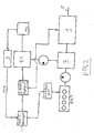
- a hybrid drive system e.g. for an industrial truck, shown schematically. It contains an internal combustion engine BKM and an electric machine E1.
- the electric machine operates on a collecting gear 1, which is coupled to the output of a shift or adjusting 2, which in turn is coupled to the shaft of the internal combustion engine BKM.
- the electric machine E1 is powered by an electric storage 4a. Its state of charge SOC is detected by a device 3 whose output signal is applied to a control and control device for the hybrid drive.
- the regulation and control unit controls or regulates the internal combustion engine BKM and the electric motor E1 via a BKM control unit and an e-machine control unit.
- a setpoint generator 4 e.g. is formed by a pedal of the vehicle, generates a target value for the speed v of the vehicle.
- FIG. 2 differs from that of FIG. 1 in that both electric machine E1 and internal combustion engine BKM are coupled to the collecting gear 2, whose output is coupled to the changeover or adjusting gear 1, which is connected to the output shaft 5 of the drive system is coupled.
- FIG. 3 differs from that of FIG. 2 in that two electric machines E1 and E2 are provided, each working on a gearbox 2.1 or 2.2.
- the shift or adjusting 1 is located between the collection gears 2.1 and 2.2.
- In the control and regulation device also passes the signal of another setpoint generator 6 for a work function, such as lifting and lowering a lifting device of the truck.
- a desired value for the speed v for the vehicle is specified. It's called v-soll-roh. It arrives at a ramp generator in which e.g. a jump signal from the pedal is only gradually driven to the final height. This is known per se.
- This setpoint value is compared in a setpoint-actual-value comparison with the actual speed v-ist, which is generated by a not shown actual value transmitter for the vehicle speed.
- the control deviation reaches a speed controller (V controller) which generates a setpoint torque M-set.
- the set torque goes to a block torque calculation or torque limitation, of which details are to be explained later.
- a setpoint value for the moment of the internal combustion engine BKM is generated, namely M-BKM-soll, which converts this setpoint value into a characteristic stage for a rotational speed n1.
- the nominal value v-soll-roh is also converted in a characteristic step into a speed signal n2.
- the speed signals n2 and n1 are added at 7 to a speed setpoint for the internal combustion engine BKM.
- the torque setpoint values of the internal combustion engine BKM are assigned approximately optimal rotational speeds.
- the vehicle speed setpoints v-soll-roh are assigned target speeds of the internal combustion engine.
- the mentioned speed values are, as mentioned, linked at 7 and given as a speed setpoint to the speed controller BKM.
- the actual speed value reaches a setpoint actual value comparison, to which the speed setpoint value is also given.
- the deviation between the setpoint and the actual value also reaches a motor model.
- the internal combustion engine inherent inertia, which expresses itself in a time delay between specification of the speed setpoint and its achievement.
- engine torque characteristic is stored at which actual rotational speeds of the internal combustion engine BKM the maximum torque value is reached.
- a corresponding limit value M-BKM limit is likewise given to the engine model in order to generate a signal M-BKM-Begr corresponding to the respective operating state of the internal combustion engine.
- This signal is taken into account in the torque calculation for the electric machine as well as the actual value of the speed v-is and the state of charge SOC of the electrical memory.
- the torque calculation also set torques for the torque controller for two electric machines E1 and E2 are generated.
- the control device associated with the internal combustion engine controls the internal combustion engine in such a way that the control deviations become sufficiently small.
- the control devices for the electric machines E1 and E2 are driven in the same way that the control errors are sufficiently small.
- the characteristic curve stage in FIG. 4 serves for the assignment of the torque setpoint values to optimum rotational speeds.
- the measured speed is naturally not equal to a certain speed, but depends on the gear ratio. This is mapped in the left block in Fig. 4 (v-Fzg / engine speed map).
- Fig. 6 two characteristic curves for charging power and discharging power are recorded.
- the optimum working range of conventional electrical storage ranges between 20% and 80% of the charge.
- the memory should not discharge below 20% and not be charged above 80%. Therefore, the characteristics shown in Fig. 6 are stored in the torque calculation block. If it is e.g. the charging power at 80%, the electric machine E1 or E2 can not be operated as a generator in such a way that it charges the memory. Conversely, an electric machine can not be operated as a motor when the charge in the memory is only 20%.
- the individual characteristic curve stages can have a plurality of characteristic curves, with which it is possible to switch between them. Such switching occurs e.g. by a manual specification by the signal of the setpoint encoder is used for this or automatically taking into account the signal of the actuating speed setpoint encoder.
- the torque calculation stage may include a sub-stage in which the desired torque for the electric machines is determined and / or limited, which are connected to a positive collecting gear or bridged superposition gear by the target torque of the electric machine is determined such that the output torque the transmission is used so that the target wheel torque assumes the required value, wherein the possible output torque of the internal combustion engine BKM, which is determined in the second Kennyliencase, is taken into account.
- the torque calculation stage may include a sub-stage in which the desired torque for the electric machine E1 / E2 is determined and / or limited, which is connected to a superposition gear, wherein the target torque the electric machine is determined so that the connected to the transmission input engine BKM is deliberately limited for the possible output torque of the BKM, which is determined in the second Kennyliench.
- the torque calculation stage may include another sub-stage in which the desired torques of the electric machine connected to a first gearbox and the second electric machine connected to a second gearbox are determined or limited when the shift or variable speed gearbox is switched to neutral wherein the electric power generatively generated by the first electric machine is consumed in a serial mode by the second electric machine and the internal combustion engine connected to the first collecting gear is loaded only up to the possible output torque of the BKM detected in the second characteristic step.
- the torque calculation stage may include a further sub-stage in which the desired torque for the electric machine E1 / E2 is determined and / or limited, which is connected to a zwangs facultyes collecting gear or a bridged superposition gear by the desired torque of the electric machine so determined is that the entire output torque of the transmission is generated solely by the electric machine E1 / E2 and takes the value required to meet the wheel torque.
- the torque calculation stage may include a fourth characteristic stage in which at least one torque-speed characteristic of an electric machine E1 / E2 is stored. From the actual speed value, the possible output torque of the electric machine is determined, possibly taking into account the comparison of the target and actual speed of the electric machine and their Moment of inertia.
- the torque calculation stage may also include a second torque limiting stage that limits the desired torques of the electric machine E1 / E2 to the values determined in the fourth characteristic step.
- the torque calculating stage may include a fifth characteristic step in which at least one temperature-loss characteristic of the electric machine is stored. From the electric motor temperature actual value of the electric machine, the allowable power loss is determined. With regard to this feature, reference is made to FIG. 7. There, a comparison is made between the measured temperature of the electric machine T-EM-ist and the maximum temperature T-EM-max. In a characteristic block or in a factor block, a factor is determined, with which the setpoint torque M-EM target of the electric machine is multiplied. It is understood that this is always ⁇ 1. This results in a limited setpoint value M-EM-Soll-Begr, as setpoint value specification for the torque controller of the electric machine E1 or E2.
- a setpoint value for example for a lifting function in an industrial truck
- the speed V-lifting is specified.
- a setpoint value is generated from this.
- this setpoint value is compared with the setpoint value, which is determined in the torque calculation stage and converted into a setpoint speed in the engine characteristic field.
- the maximum value stage Max the larger of the two speed setpoint values (driving function and work function) is determined and forwarded to the control device for the rotational speed of the internal combustion engine.
- the function of the drive system according to FIG. 5 is otherwise the same as in FIG. 4.
- a mode switching stage for bypassing the overlapping operation may also be controlled by a control and regulating device which controls the switching elements of the lock-up device. It can be designed for separating or closing clutches and brakes. Another control or regulating device may control the operation of the switching elements of the clutches and / or brakes.
- the mode change stage can switch the drive system to a serial mode by operating clutches and brakes, in which the power generated by the internal combustion engine BKM is purely electric from the first electric motor E1 operating as a generator to the second electric machine E2 operating as a traction motor. transfer.
- the mode switching stage may switch the drive system to a split-mode operation by operating clutches and brakes in which a portion of the power generated by engine BKM is electrically supplied from the first electric machine E1 operating as a generator or motor to the second electric machine serving as a motor or engine Generator operates, is transmitted and the other part of the power is transmitted mechanically to the transmission shafts to the output.
- the mode change stage can switch the drive system by operating clutches and brakes in a parallel operation, in which sum up the power generated by the internal combustion engine BKM and at least one electric machine.
- the mode change stage can switch the drive system by operating clutches and brakes in a purely electrical operation, the internal combustion engine is switched off.
- the different operating modes can be realized via different controllers, characteristic stages and torque calculation stages.
- the drive system shown can also have an operating strategy stage which, from certain input signals and / or characteristic curves for the respective Operating state determines the most advantageous mode and controls the subsequent mode change stage.
- the operating strategy stage can determine and compare the energy consumption in the individual operating modes and can generate desired signals for the operating mode change stage in order to switch to the most favorable operating mode, hystereses being provided to avoid oscillation circuits.
- the mode switching stage may compare state variables of the drive system with switching conditions and send prescriptions to the control devices of the shifting elements of the transmissions, the clutches and the lock-up device.
Landscapes
- Engineering & Computer Science (AREA)
- Transportation (AREA)
- Mechanical Engineering (AREA)
- Power Engineering (AREA)
- Automation & Control Theory (AREA)
- Life Sciences & Earth Sciences (AREA)
- Sustainable Development (AREA)
- Sustainable Energy (AREA)
- Electric Propulsion And Braking For Vehicles (AREA)
- Hybrid Electric Vehicles (AREA)
- Control Of Vehicle Engines Or Engines For Specific Uses (AREA)
Applications Claiming Priority (1)
| Application Number | Priority Date | Filing Date | Title |
|---|---|---|---|
| DE102006045502A DE102006045502A1 (de) | 2006-09-27 | 2006-09-27 | Vorrichtung zur Regelung eines Hybrid-Antriebssystems für ein Kraftfahrzeug, insbesondere ein Flurförderzeug |
Publications (1)
| Publication Number | Publication Date |
|---|---|
| EP1905638A2 true EP1905638A2 (fr) | 2008-04-02 |
Family
ID=38924290
Family Applications (1)
| Application Number | Title | Priority Date | Filing Date |
|---|---|---|---|
| EP07015751A Withdrawn EP1905638A2 (fr) | 2006-09-27 | 2007-08-10 | Dispositif destiné au réglage d'un système d'entraînement hybride pour un véhicule automobile, en particulier un chariot de manutention |
Country Status (4)
| Country | Link |
|---|---|
| US (1) | US7922616B2 (fr) |
| EP (1) | EP1905638A2 (fr) |
| CN (1) | CN101152865A (fr) |
| DE (1) | DE102006045502A1 (fr) |
Cited By (2)
| Publication number | Priority date | Publication date | Assignee | Title |
|---|---|---|---|---|
| WO2013056907A1 (fr) * | 2011-10-21 | 2013-04-25 | Zf Friedrichshafen Ag | Procédé permettant de faire fonctionner une chaîne cinématique d'un véhicule hybride |
| CH706518A1 (de) * | 2012-05-15 | 2013-11-15 | Liebherr Machines Bulle Sa | Steuerung für das Antriebssystem einer Arbeitsmaschine. |
Families Citing this family (13)
| Publication number | Priority date | Publication date | Assignee | Title |
|---|---|---|---|---|
| JP5217430B2 (ja) * | 2007-12-28 | 2013-06-19 | トヨタ自動車株式会社 | オルタネータ制御装置およびオルタネータ制御方法 |
| JP4806704B2 (ja) | 2008-12-04 | 2011-11-02 | 本田技研工業株式会社 | 車両用走行制御装置 |
| US8008800B2 (en) * | 2009-05-22 | 2011-08-30 | Deere & Company | Harvester multiple engine energy control system |
| US8790215B2 (en) | 2011-01-13 | 2014-07-29 | Cummins Inc. | System, method, and apparatus for controlling power output distribution in a hybrid power train |
| US8795008B2 (en) | 2011-04-06 | 2014-08-05 | Twin Disc, Inc. | Two-into-two or one hybrid power device for a marine vehicle |
| EP2583854B1 (fr) * | 2011-10-21 | 2017-06-21 | Volvo Car Corporation | Ensemble de moteur |
| DE102012201241A1 (de) * | 2012-01-30 | 2013-08-01 | Robert Bosch Gmbh | Vorrichtung zur Regelung eines Motors |
| CN103441553B (zh) * | 2013-09-11 | 2015-06-17 | 山东省科学院自动化研究所 | 一种基于电池并联的电动汽车模块化动力系统及控制方法 |
| US9547314B2 (en) * | 2014-05-20 | 2017-01-17 | GM Global Technology Operations LLC | System and method for controlling vehicle acceleration |
| DE102015200856A1 (de) * | 2015-01-20 | 2016-07-21 | Mahle International Gmbh | Verfahren zur Regelung einer Drehzahl |
| DE102015112711A1 (de) * | 2015-08-03 | 2017-02-23 | Borgward Trademark Holdings Gmbh | Verfahren und System zum Kontrollieren von Geschwindigkeitsüberschreitungen eines Elektrofahrzeugs |
| EP3707041A1 (fr) * | 2017-11-07 | 2020-09-16 | Hyster-Yale Group, Inc. | Commande de transmission variable en continu |
| EP3825067A1 (fr) * | 2019-11-21 | 2021-05-26 | Hilti Aktiengesellschaft | Procédé de fonctionnement d'une machine-outil et machine-outil |
Family Cites Families (11)
| Publication number | Priority date | Publication date | Assignee | Title |
|---|---|---|---|---|
| US3566717A (en) * | 1969-03-17 | 1971-03-02 | Trw Inc | Power train using multiple power sources |
| JP3211751B2 (ja) * | 1997-03-24 | 2001-09-25 | トヨタ自動車株式会社 | 動力出力装置およびその制御方法 |
| JP3451935B2 (ja) * | 1998-06-03 | 2003-09-29 | 日産自動車株式会社 | ハイブリッド車両の駆動力制御装置 |
| DE19955311C2 (de) * | 1999-11-17 | 2003-12-24 | Jungheinrich Ag | Antriebssystem für ein Flurförderzeug |
| JP4043690B2 (ja) * | 2000-04-27 | 2008-02-06 | 本田技研工業株式会社 | ハイブリッド車両の駆動力制御装置 |
| JP3593983B2 (ja) * | 2001-01-16 | 2004-11-24 | 日産自動車株式会社 | 車両の駆動力制御装置 |
| US6553287B1 (en) * | 2001-10-19 | 2003-04-22 | Ford Global Technologies, Inc. | Hybrid electric vehicle control strategy to achieve maximum wide open throttle acceleration performance |
| DE10340472B4 (de) * | 2003-09-03 | 2008-07-03 | Jungheinrich Ag | Antriebssystem für ein Flurförderzeug |
| JP4192991B2 (ja) * | 2004-07-12 | 2008-12-10 | トヨタ自動車株式会社 | 動力出力装置およびこれを搭載する車両並びにその制御方法 |
| JP4086018B2 (ja) * | 2004-07-15 | 2008-05-14 | トヨタ自動車株式会社 | ハイブリッド車およびその制御方法並びに動力出力装置 |
| JP4241676B2 (ja) * | 2005-06-27 | 2009-03-18 | トヨタ自動車株式会社 | 動力出力装置およびこれを搭載する車両並びに動力出力装置の制御方法 |
-
2006
- 2006-09-27 DE DE102006045502A patent/DE102006045502A1/de not_active Ceased
-
2007
- 2007-08-10 EP EP07015751A patent/EP1905638A2/fr not_active Withdrawn
- 2007-09-26 US US11/861,365 patent/US7922616B2/en not_active Expired - Fee Related
- 2007-09-26 CN CNA2007101543679A patent/CN101152865A/zh active Pending
Cited By (2)
| Publication number | Priority date | Publication date | Assignee | Title |
|---|---|---|---|---|
| WO2013056907A1 (fr) * | 2011-10-21 | 2013-04-25 | Zf Friedrichshafen Ag | Procédé permettant de faire fonctionner une chaîne cinématique d'un véhicule hybride |
| CH706518A1 (de) * | 2012-05-15 | 2013-11-15 | Liebherr Machines Bulle Sa | Steuerung für das Antriebssystem einer Arbeitsmaschine. |
Also Published As
| Publication number | Publication date |
|---|---|
| US20080076622A1 (en) | 2008-03-27 |
| US7922616B2 (en) | 2011-04-12 |
| DE102006045502A1 (de) | 2008-04-03 |
| CN101152865A (zh) | 2008-04-02 |
Similar Documents
| Publication | Publication Date | Title |
|---|---|---|
| EP1905638A2 (fr) | Dispositif destiné au réglage d'un système d'entraînement hybride pour un véhicule automobile, en particulier un chariot de manutention | |
| EP3377353B1 (fr) | Procédé de contrôle d'un dispositif de propulsion d'un véhicule hybride et véhicule hybride | |
| DE102007053781B4 (de) | Verfahren und ein Steuersystem zur Optimierung und Steuerung eines Hybridantriebsstrangsystems | |
| EP1472108B9 (fr) | Procede de reglage du point de fonctionnement de l'entrainement hybride d'un vehicule | |
| DE102005022247B4 (de) | Diagnoseverfahren für eine Drehmomentsteuerung eines elektrisch verstellbaren Getriebes | |
| DE102005006149B4 (de) | Gaswegnahmesteuerung | |
| DE102008005367B4 (de) | Verfahren und Vorrichtung zum Überwachen von Einrichtungen eines Hydraulikkreises eines elektromechanischen Getriebes | |
| DE19932118C1 (de) | Elektrischer Mehrfachmotorenantrieb für ein Kraftfahrzeug | |
| EP2190710A2 (fr) | Procédé pour déplacer le point de charge en fonctionnement hybride pour un véhicule à fonctionnement hybride en parallèle | |
| DE102007049253B4 (de) | Verfahren zur Regelung eines Leistungsverzweigungsgetriebes | |
| EP3006245A1 (fr) | Procede de commande de transmission | |
| EP1876080A2 (fr) | Système d'entraînement pour un chariot de manutention doté d'un moteur à combustion interne | |
| DE102005021801A1 (de) | Verfahren für den aktiven Motorhalt eines Hybridelektrofahrzeugs | |
| WO2005047039A2 (fr) | Systeme d'entrainement hybride pour vehicule automobile | |
| DE102007050599A1 (de) | Verfahren und Vorrichtung zum Steuern des Betriebes eines Hydrauliksteuerkreises für ein elektromechanisches Getriebe | |
| WO2003062009A1 (fr) | Procédé pour régler un état de marche nominal pour un véhicule à entraînement hybride | |
| DE102010028658A1 (de) | Verfahren und Vorrichtung zur automatischen Steuerung des Gangs eines Elektrofahrrad-Getriebes | |
| DE102008053505A1 (de) | Verfahren zur Steuerung eines Hybridantriebsstrangs eines Kraftfahrzeuges | |
| WO2008015049A1 (fr) | Dispositif de commande d'un groupe propulseur hybride | |
| DE102016209850B4 (de) | Verfahren und Anordnung zur Steuerung einer Stellgrösse eines Antriebsstrangsystems | |
| DE60319683T2 (de) | Steuervorrichtung für hybridfahrzeug | |
| DE102006005470A1 (de) | Verfahren zum Betreiben eines Parallelhybridantriebsstranges eines Fahrzeugs | |
| DE19955313A1 (de) | Antriebssystem für Flurförderzeuge | |
| DE102012222366A1 (de) | Steuerungssystem eines Hybridfahrzeugs | |
| DE102006020934B4 (de) | Antriebsstrangvorrichtung eines Fahrzeuges |
Legal Events
| Date | Code | Title | Description |
|---|---|---|---|
| PUAI | Public reference made under article 153(3) epc to a published international application that has entered the european phase |
Free format text: ORIGINAL CODE: 0009012 |
|
| AK | Designated contracting states |
Kind code of ref document: A2 Designated state(s): AT BE BG CH CY CZ DE DK EE ES FI FR GB GR HU IE IS IT LI LT LU LV MC MT NL PL PT RO SE SI SK TR |
|
| AX | Request for extension of the european patent |
Extension state: AL BA HR MK YU |
|
| STAA | Information on the status of an ep patent application or granted ep patent |
Free format text: STATUS: THE APPLICATION IS DEEMED TO BE WITHDRAWN |
|
| 18D | Application deemed to be withdrawn |
Effective date: 20100302 |