EP1905596A1 - Halterung zur Befestigung eines Tintenbehälters und Tintenbehälter - Google Patents
Halterung zur Befestigung eines Tintenbehälters und Tintenbehälter Download PDFInfo
- Publication number
- EP1905596A1 EP1905596A1 EP07015660A EP07015660A EP1905596A1 EP 1905596 A1 EP1905596 A1 EP 1905596A1 EP 07015660 A EP07015660 A EP 07015660A EP 07015660 A EP07015660 A EP 07015660A EP 1905596 A1 EP1905596 A1 EP 1905596A1
- Authority
- EP
- European Patent Office
- Prior art keywords
- holder
- ink tank
- retainer
- ink
- memory device
- Prior art date
- Legal status (The legal status is an assumption and is not a legal conclusion. Google has not performed a legal analysis and makes no representation as to the accuracy of the status listed.)
- Granted
Links
- 238000012545 processing Methods 0.000 claims abstract description 5
- 238000009434 installation Methods 0.000 description 6
- 238000007639 printing Methods 0.000 description 5
- WABPQHHGFIMREM-UHFFFAOYSA-N lead(0) Chemical compound [Pb] WABPQHHGFIMREM-UHFFFAOYSA-N 0.000 description 2
- 238000004519 manufacturing process Methods 0.000 description 2
- 230000004913 activation Effects 0.000 description 1
- 238000004026 adhesive bonding Methods 0.000 description 1
- 238000013461 design Methods 0.000 description 1
- 238000001514 detection method Methods 0.000 description 1
- 238000005516 engineering process Methods 0.000 description 1
- 238000001746 injection moulding Methods 0.000 description 1
- 238000003780 insertion Methods 0.000 description 1
- 230000037431 insertion Effects 0.000 description 1
- 230000007257 malfunction Effects 0.000 description 1
- 238000000034 method Methods 0.000 description 1
- 238000012986 modification Methods 0.000 description 1
- 230000004048 modification Effects 0.000 description 1
- 238000012544 monitoring process Methods 0.000 description 1
Images


Classifications
-
- B—PERFORMING OPERATIONS; TRANSPORTING
- B41—PRINTING; LINING MACHINES; TYPEWRITERS; STAMPS
- B41J—TYPEWRITERS; SELECTIVE PRINTING MECHANISMS, i.e. MECHANISMS PRINTING OTHERWISE THAN FROM A FORME; CORRECTION OF TYPOGRAPHICAL ERRORS
- B41J2/00—Typewriters or selective printing mechanisms characterised by the printing or marking process for which they are designed
- B41J2/005—Typewriters or selective printing mechanisms characterised by the printing or marking process for which they are designed characterised by bringing liquid or particles selectively into contact with a printing material
- B41J2/01—Ink jet
- B41J2/17—Ink jet characterised by ink handling
- B41J2/175—Ink supply systems ; Circuit parts therefor
- B41J2/17503—Ink cartridges
- B41J2/1752—Mounting within the printer
-
- B—PERFORMING OPERATIONS; TRANSPORTING
- B41—PRINTING; LINING MACHINES; TYPEWRITERS; STAMPS
- B41J—TYPEWRITERS; SELECTIVE PRINTING MECHANISMS, i.e. MECHANISMS PRINTING OTHERWISE THAN FROM A FORME; CORRECTION OF TYPOGRAPHICAL ERRORS
- B41J2/00—Typewriters or selective printing mechanisms characterised by the printing or marking process for which they are designed
- B41J2/005—Typewriters or selective printing mechanisms characterised by the printing or marking process for which they are designed characterised by bringing liquid or particles selectively into contact with a printing material
- B41J2/01—Ink jet
- B41J2/17—Ink jet characterised by ink handling
- B41J2/175—Ink supply systems ; Circuit parts therefor
- B41J2/17503—Ink cartridges
- B41J2/17543—Cartridge presence detection or type identification
- B41J2/17546—Cartridge presence detection or type identification electronically
Definitions
- the invention relates to a device for supplying ink to an ink jet recording apparatus comprising a retainer which retainer is provided with an ink receiving device.
- the invention further relates to a holder and an ink tank for such a device.
- Ink jet recording apparatuses such as printers, plotters, copying machines, facsimile machines and the like, are widely used.
- a recording apparatus has a cartridge mounting portion or retainer for detachably accepting an ink cartridge for supplying ink to a recording or print head.
- Various types of the recording apparatuses are known wherein most of them use one of the three technologies thermal, piezoelectric, and/or continuous.
- the print head or recording head may be formed integrally with the retainer, and the retainer and/or the print head may be mounted on a carriage, which is reciprocally moved relative to a print medium.
- the receiving portion is provided on a stationary part of the apparatus, wherein ink is supplied from the receiving device of the retainer to a print head via an ink tube or the like.
- the print head is part of the disposable ink cartridge, wherein the ink cartridge and the print head may come in two pieces, which are combined prior to mounting to the retainer.
- ink cartridges have been equipped with a memory chip, e.g. for monitoring the amount of ink consumed.
- the memory chip is accessible through contact elements, wherein the retainer is provided with respective terminal elements connected to a processing unit on the recording apparatus and/or a computer or the like connected to the recording apparatus.
- a contact between the terminal elements on the retainer and the contact elements on the ink cartridge must be guaranteed. Therefore, it is known to provide the ink cartridge and the retainer with respective engagement elements.
- the engagement elements may be exposed to wear and/or undesired plastic deformation, which may result in a malfunction of the engagement elements.
- a holder for mounting on a retainer of an ink jet recording apparatus having an ink receiving device and a terminal portion is provided, said holder being formed as an at least partially open shell for receiving at least one ink tank, and said holder comprising at least one contact element provided on an outer surface of said holder for contacting a respective terminal portion provided on the retainer.
- the disposable ink cartridge is divided in two parts, namely a holder and a (disposable) ink tank.
- the holder is provided with contact elements for contacting the terminal portion on the retainer.
- the (disposable) ink tank may be designed relatively simple, compared with the holder.
- different holders may be necessary, wherein different holders may be designed to receive a common ink tank. This allows a user to modify several printing apparatuses by installing respective holders and using the same ink tank or ink tanks of the same type in different printing apparatuses. Consequently, the consumer is no longer forced to remember his printer type for buying ink tanks. In addition, the costs for manufacturing a respective ink tank may be further reduced.
- the holder comprises at least one engagement element for cooperating with a respective mounting element on the retainer.
- engagement elements for cooperating with the retainer of the recording apparatus are part of an intermediate element or holder and no longer part of the disposable product.
- the engagement element is formed so as to ensure reliably a stable contact between the contact element on the holder and the contact portion on the retainer. Shape, size and/or positioning of engagement elements and/or the contact elements provided on the holder are chosen to meet requirements of a recording apparatus.
- at least one connecting element may be provided on the holder for securing a respective ink tank on installation.
- a memory device is provided on said holder, wherein said at least one contact element is connected to said memory device.
- the memory device and the contact elements may be provided on a common circuit board or chip element.
- said at least one contact element is connected to an internal contact element provided on an inner surface of said holder.
- the internal contact elements may be provided on any wall of said holder.
- the (outer) contact elements and the internal contact elements may be connected to the internal contact elements using an electrical connector.
- an electrical connector may be consisting of wire that electrically connects two circuit points.
- the internal contact elements may be provided on a circuit board on which also said memory device is provided.
- At least two contact elements are provided on the outer surface of the holder, wherein a first contact element is connected to a memory device provided on said holder and the second contact element is connected to an internal contact member formed for contacting a respective contact element provided on said ink tank.
- two internal contact members are provided which are contacting one common contact element provided on the ink tank, wherein an electrical circuit is shorted by inserting a respective ink tank. This allows a reliable detection of an inserted ink tank.
- resetting means are provided for resetting said memory device.
- said memory device may be reset without detaching the holder from the retainer.
- the resetting means may be realized as internal resetting means, wherein for example a counter is automatically reset to zero once a maximum value is reached.
- the resetting means include an external element, which preferably, is provided on a part of the holder not accessible if the ink tank is attached to the holder. Thereby, a misuse of the external resetting element during operation is prevented.
- actuating means are provided for triggering the resetting means when mounting an ink tank on said holder and/or removing an ink tank from said holder.
- Resetting of said memory device may be achieved by shorting a circuit. If resetting is achieved when mounting the ink tank and/or removing the ink tank, the use of such a system is very convenient.
- means may be provided for detecting if the same cartridge is re-installed without being refilled. This means may include a second memory device provided on the ink tank.
- an ink tank for mounting on said holder is provided.
- said ink tank is provided with at least one connecting member, in particular a positioning, fixing and/or clamping element, for co-operating with a respective connecting element of said holder.
- the ink tank is provided with at least one protection member, for preventing handling of said engagement element of said holder, if the ink tank is inserted in said holder.
- the holder may be installed permanently in the recording apparatus, e.g. by gluing the holder to the retainer or the like. However, in most cases, the user may prefer to maintain the possibility of removing the holder.
- the ink tank is provided with means which prevent a conjoint handling. As a result, the holder may only be removed from the receiving portion after the ink tank has been removed.
- the ink tank is provided with an ink supply port to be mounted on a respective ink supply needle formed on the retainer.
- An ink receiving device formed with an ink supply needle is typically used in a piezoelectric ink jet recording apparatus. For other printers, different receiving devices may be advantageous.
- a device for supplying ink to an recording apparatus comprising a retainer which retainer is provided with an ink receiving device is provided, the device comprising at least one holder for mounting to the retainer and at least one ink tank for mounting to the holder.
- the holder and/or the ink tank are provided with locking elements for preventing a conjoint handling of the holder and the ink tank.
- means are provided for avoiding a removal of the holder while removing the ink tank.
- means are provided for preventing from a conjoint installation of the two parts. Thereby, one may ensure that the holder is installed properly prior to installation of the ink tank. Of course, conjoint use of the holder and the ink tank after installation in the printer is not hindered.
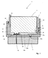
- Figure 1 is a cross-sectional side view of a device 1 according to a first embodiment of the invention comprising a holder 2 and an ink tank 3, wherein the holder 3 is operably secured to a retainer 4 of a recording apparatus (not depicted).
- the retainer 4 is provided with an ink receiving device 42 comprising am ink supply needle 43, terminal portions 41 connected to a processing unit (not depicted), and mounting elements 40, 40a.
- the holder 2 comprises two opposing sidewalls 22, 23 and a bottom 24. Further sidewalls, connecting the opposing sidewalls 22, 23 may be provided, but are not visible in fig. 1.
- the holder 2 On a first sidewall 22, on the right in fig. 1, the holder 2 is provided with contact elements 21 for contacting the terminal portions 41 of the retainer 4.
- the holder 2 is provided with engagement elements 20, 20a, which cooperate with counterparts 40, 40a of the retainer 4 so that the holder 2 is exactly positioned within the retainer 4.
- the bottom 24 of the holder 2 is provided with a protrusion 20a which is inserted into a recess 40a of the retainer 4.
- the sidewall 44 of the retainer 4 is designed as a locking element with a notch 40 for locking the holder 2 within the retainer 4.
- the contact elements 21 are exactly positioned with respect to their cooperating elements, i.e., the terminal portions 41 of the retainer 4.
- the two sidewalls 22, 23 of the holder 2 position the ink tank 3 in a predetermined location.
- the holder 2 is further provided with connecting elements for retaining the ink tank 3 within the holder 2.
- the left sidewall 23 is provided with a notch 25 facing towards the inside which cooperates with an edge of the ink tank 3.
- the bottom 24 of the holder 2 has an elongated hole 24a through which an ink supply port 32 of the ink tank 3 may extend for mounting the ink tank 3 to the ink receiving device 42 of the retainer 4.
- the contact elements 21 are provided on a part of the holder 2, which is resiliently movable with respect to the terminal portion 41. If no ink tank 3 is installed, the contact elements 21 are forced apart from the terminal members 41. The ink tank 3 forces the contact elements 21 in the direction of the terminal members 41 for establishing a respective contact.
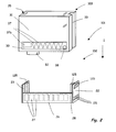
- FIG 2 is a perspective schematic view of an inventive device 101 comprising a holder 102 and an ink tank 103 according to a second embodiment of the present invention.
- the holder 102 may be operably secured to a retainer according to figure 1 (not depicted in figure 2) of a recording apparatus.
- the holder 102 is provided with an engagement element 120, which in the depicted embodiment is formed as a lever, for cooperating with a respective mounting element (non-depicted) formed on said retainer.
- contact elements 121 are provided on an outer-surface of the sidewall 22 of the holder 102.
- a number of contacts 121, their position on the holder 2, their shape and/or their size is chosen so as to match a respective terminal portion provided on the non-depicted retainer.
- contact elements 121 are provided in two parallel rows, which are in parallel to a bottom surface 24 (see figure 1) of the holder 102, wherein the number of contact elements 121 of a lower row with respect to an insertion direction I is larger than the number of contact elements 121 of an upper row.
- the contact elements 121 have a circular base area and are essentially aligned in one plane with the outer surface of the sidewall 22 of the holder 102.
- other shapes are also possible, e.g.
- the holder 102 is formed as an open shell, wherein the depicted holder 102 comprises three sidewalls 22, 23, 26 and a bottom wall (non-visible in figure 2) forming a parallelepiped. In other embodiments the holder 102 may comprise four sidewalls and/or no bottom wall. In still another embodiment, the holder may have a different shape, e.g. a cylindrical or prism shape.
- the contact elements 121 and the lever 120 are provided on the same sidewall 22.
- the contact elements 121 and an engagement element may be provided on different sidewalls, e.g. on opposing sidewalls as shown in figure 1.
- the sidewall 22 on which the lever 120 and the contact elements 121 are provided is shorter in length than a adjacent sidewall 26.
- the two opposing sidewalls 22, 23, denoted as the left sidewall 23 and the right sidewall 22, are provided with connecting elements 125 for positioning of the ink tank 103.
- the lead wire may be formed integrally with the holder 102 for example during an injection moulding of the holder 102.
- the holder 102 may be affixed to a retainer and the ink tank 103 may be mounted on the holder 102.
- the ink tank 103 may be replaced without removing the holder 102 from the retainer.
- the ink tank 103 may be amounted to the holder 102, wherein the ink tank 103 is provided with a positioning grove 35 for engaging with the connecting elements 125 of the holder 102.
- the depicted ink tank 103 is formed as a cuboid, wherein an integrated circuit element or chip 30 is provided on one sidewall 31 of the ink tank 3.
- the chip 30 comprises contact members 37, 37a for contacting the internal contact elements 27 of the holder 102 and a memory device 38.
- the manufacturer is forced to locate contact elements on the ink tank so as to match the positions of terminal members on the printer.
- the size of internal contact elements 27 may be chosen to be larger than the size of terminal elements provided on a retainer, so as to enhance the stability of the contact.
- the position of internal contact elements 27 may be chosen so as to avoid any interference with the engagement elements 20 and/or the connecting elements 125.
- the number of contact members 37, 37a is smaller than the number of internal contact elements 27 on the holder 102, wherein one contact member 37a is arranged for touching two contact elements 27 on the holder 102.
- Figure 3 is schematic view of a device 201 comprising a holder 202 and an ink tank 203 according to a third embodiment of the invention.
- the device 201 is similar to the device 101 shown in figure 2.
- identical reference signs are used and a detailed description of these elements is omitted.
- the device 201 depicted in fig. 3 is provided with two memory devices 29 and 38, wherein a first memory device 29 is provided on the holder 202 and a second memory device is provided on the ink tank 203.
- the contact elements 221 a, 221 b provided on the surface 22 of the holder 202 are divided in two groups, wherein a first group of contact elements 221 a is electrically connected to the first memory device 29 on the holder 202 and the second group of contact elements 221 b is connected to internal contacts 27 provided on an inner surface of the sidewall 26.
- the two memory devices 29, 38 may be used for storing different kinds of information.
- the amount of ink consumed may be stored in the memory device 38 provided on the ink tank 203, wherein the number of subsequently installed ink tanks and other information may be stored in the memory device 29 on the holder 202.
- the memory device 29 and the respective contact elements 221 a may be formed on a circuit board or chip.
- the ink tank 203 is provided with a protection member 33, which in the depicted embodiment is formed as a projecting element covering the lever 120 when the ink tank 203 is mounted on the holder 202.
- Figure 4 is schematic view of a device 301 comprising a holder 302 and an ink tank 303 according to a forth embodiment of the invention.
- the device 301 is similar to the device 201 shown in figure 3.
- identical reference signs are used and a detailed description of these elements is omitted.
- the device 301 depicted in fig. 4 is also provided with two memory devices 29 and 38, wherein the first memory device 29 is provided on the holder 302 and a second memory device is provided on the ink tank 303.
- Star shaped contact elements 321 provided on the outer surface of the sidewall 22 of the holder 302 are connected to internal contact elements 327a, 327b provided on an inner surface of the holder 302.
- the internal contact elements 327a, 327b are divided in two groups, wherein a first group of contact elements 327a is electrically connectable to respective contact members 37, 37a on the ink tank 303 and the second group of contact elements 327b is connected to the first memory device 29 on the holder 302.
- the second group of contacts 327b and the memory device 29 are provided on a chip 329.
- an actuating element 5 comprising a push button is provided on the holder 302 for resetting the memory device 29.
- indicating means are provided for indicating the status of the memory device 29.
- means for resetting the memory device 29 provided on the holder 302 may be realized so as the memory device 29 is reset when mounting the ink tank 303 to the holder 302 and/or removing the ink tank 303 from the holder 302. This may be accomplished by shorting a circuit and/or interrupting a circuit line.
- an automatic reset may be programmed to the chip 329, wherein for example the memory device is reset to zero, once a counter for ink droplets has reached a maximum value.
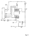
- FIG. 5 shows schematically an electrical circuit for realizing a reset function.
- the circuit comprises a microprocessor, which in the depicted embodiment is an EM78P153E.
- EM78P153S is an 8-bit microprocessor with low-power and high-speed CMOS.
- FIG. 6 is schematic view of a device 401 comprising a holder 402 and an ink tank 403 according to a fifth embodiment of the invention.
- the device 401 is similar to the devices shown above and for identical or like elements identical reference signs are used and a detailed description of these elements is omitted.
- a first group of contact elements 121 is provided on the outer surface of the sidewall 22 of the holder 402.
- the contact elements 121 are connected to the memory device 29.
- a second group of contacts elements 421 is provided on an inner surface of the holder 402 and depicted in broken lines in fig. 5.
- the contact elements 421 of the second group are also connected to the memory device 29.
- the memory device 29 is equipped with means for resetting the memory device 29 in response to a short-circuit.
- the internal contact elements 37 may be connected to contact elements 121 on the outside of the holder 402.
- shorting the internal contact elements 37 by installing the ink tank also shorts the respective contact elements 121 on the outside of the holder 402, connected to a processing unit (not depicted) of a printing device.
- installation of the ink tank may be detected by the printing device, resulting in an activation of the ink tank, sending a reset signal to the memory device or the like.
- FIG 7 is a schematic view of a device 501 according to a sixth embodiment of the present invention.
- the device 501 comprises a holder 502 on which an ink tank 503 is mounted.
- Figure 8 is a side view of the holder 502 according to figure 7.
- the holder 502 comprises a lever 520 for cooperating with mounting elements of a non-depicted ink jet recording apparatus and a chip 529 with contact elements 421 and a memory device 529.
- the ink tank 503 is provided with a grip element 534.
- On the grip element a wedge element 535 is formed for preventing the lever 520 of the holder 502 from being moved as long as the ink tank 503 is mounted to the holder 502.
- a resilient element 525 is provided on a sidewall 526 of the holder 502 .
- the resilient element 525 is projecting to the inside of the holder 502 if no forces are exerted on it. Thereby the resilient element 525 is preventing an ink tank 503 from being accidentally mounted on the holder 502.
- the holder 502 is further provided with shoulders 524 for allowing a better installation of the holder 502 on a retainer as shown in figure 1.
Priority Applications (4)
| Application Number | Priority Date | Filing Date | Title |
|---|---|---|---|
| AT06020342T ATE492401T1 (de) | 2006-09-27 | 2006-09-27 | Tintenkassettehalterung für druckgeräthaltevorrichtung |
| EP06020342A EP1905594B1 (de) | 2006-09-27 | 2006-09-27 | Tintenkassettehalterung für Druckgeräthaltevorrichtung |
| EP07015660A EP1905596B1 (de) | 2006-09-27 | 2007-08-15 | Halterung zur Befestigung eines Tintenbehälters und Tintenbehälter |
| DE202007018805U DE202007018805U1 (de) | 2006-09-27 | 2007-08-15 | Halter zum Halten eines Tintentanks und Tintentank |
Applications Claiming Priority (2)
| Application Number | Priority Date | Filing Date | Title |
|---|---|---|---|
| EP06020342A EP1905594B1 (de) | 2006-09-27 | 2006-09-27 | Tintenkassettehalterung für Druckgeräthaltevorrichtung |
| EP07015660A EP1905596B1 (de) | 2006-09-27 | 2007-08-15 | Halterung zur Befestigung eines Tintenbehälters und Tintenbehälter |
Publications (2)
| Publication Number | Publication Date |
|---|---|
| EP1905596A1 true EP1905596A1 (de) | 2008-04-02 |
| EP1905596B1 EP1905596B1 (de) | 2012-01-04 |
Family
ID=40794750
Family Applications (2)
| Application Number | Title | Priority Date | Filing Date |
|---|---|---|---|
| EP06020342A Active EP1905594B1 (de) | 2006-09-27 | 2006-09-27 | Tintenkassettehalterung für Druckgeräthaltevorrichtung |
| EP07015660A Active EP1905596B1 (de) | 2006-09-27 | 2007-08-15 | Halterung zur Befestigung eines Tintenbehälters und Tintenbehälter |
Family Applications Before (1)
| Application Number | Title | Priority Date | Filing Date |
|---|---|---|---|
| EP06020342A Active EP1905594B1 (de) | 2006-09-27 | 2006-09-27 | Tintenkassettehalterung für Druckgeräthaltevorrichtung |
Country Status (4)
| Country | Link |
|---|---|
| EP (2) | EP1905594B1 (de) |
| AT (2) | ATE492401T1 (de) |
| DE (3) | DE602006019098D1 (de) |
| ES (1) | ES2378256T3 (de) |
Cited By (11)
| Publication number | Priority date | Publication date | Assignee | Title |
|---|---|---|---|---|
| WO2010130219A1 (zh) * | 2009-05-13 | 2010-11-18 | 珠海纳思达企业管理有限公司 | 喷墨打印机上的适配器及墨盒 |
| WO2011097842A1 (en) * | 2010-02-11 | 2011-08-18 | Ronghua Sun | Ink cartridge holder, ink cartridge, and ink jet printing system |
| CN102161278A (zh) * | 2008-06-30 | 2011-08-24 | 兄弟工业株式会社 | 用于墨盒的转接器 |
| EP2431184A1 (de) * | 2009-05-13 | 2012-03-21 | Zhuhai Ninestar Management Co., Ltd. | Adapter für einen tintenstrahldrucker und damit verwendete tintenpatrone |
| US8172382B2 (en) * | 2008-06-30 | 2012-05-08 | Brother Kogyo Kabushiki Kaisha | Container arrangement including ink tank and adapter configured to be mounted to ink tank |
| CN102582258A (zh) * | 2011-01-14 | 2012-07-18 | 精工爱普生株式会社 | 容器单元以及液体喷射系统 |
| EP3248801A1 (de) * | 2016-05-26 | 2017-11-29 | OCE Holding B.V. | Tintenstrahldruckvorrichtung |
| JP2021519708A (ja) * | 2018-07-13 | 2021-08-12 | ヒューレット−パッカード デベロップメント カンパニー エル.ピー.Hewlett‐Packard Development Company, L.P. | 印刷液体サプライ |
| US11364720B2 (en) | 2018-07-13 | 2022-06-21 | Hewlett-Packard Development Company, L.P. | Print liquid supply |
| US11420444B2 (en) | 2018-07-13 | 2022-08-23 | Hewlett-Packard Development Company, L.P. | Print liquid supply |
| US11667124B2 (en) | 2018-07-13 | 2023-06-06 | Hewlett-Packard Development Company, L.P. | Print liquid supply |
Families Citing this family (4)
| Publication number | Priority date | Publication date | Assignee | Title |
|---|---|---|---|---|
| DE202008018040U1 (de) | 2008-07-25 | 2011-05-05 | BROTHER KOGYO K.K., Nagoya-shi | Adapter für Tintenpatrone |
| JP5962144B2 (ja) | 2012-03-30 | 2016-08-03 | ブラザー工業株式会社 | 印刷流体収容装置及び印刷流体供給装置 |
| JP6019697B2 (ja) | 2012-04-19 | 2016-11-02 | ブラザー工業株式会社 | 印刷流体収容装置及び印刷流体供給装置 |
| JP6512774B2 (ja) * | 2014-08-25 | 2019-05-15 | キヤノン株式会社 | 液体収納容器の保持部材、プリントヘッドおよびプリンタ |
Citations (3)
| Publication number | Priority date | Publication date | Assignee | Title |
|---|---|---|---|---|
| EP0440261A2 (de) | 1990-02-02 | 1991-08-07 | Canon Kabushiki Kaisha | Tintenstrahlgerät und seine Tintenkassette |
| EP0854045A2 (de) | 1997-01-21 | 1998-07-22 | Hewlett-Packard Company | Tintenpatrone mit getrennt austauschbarem Tintenbehälter |
| DE19917229A1 (de) | 1999-04-16 | 2000-10-26 | Elmos Semiconductor Ag | Tintenkassette für einen Tintenstrahldrucker |
Family Cites Families (4)
| Publication number | Priority date | Publication date | Assignee | Title |
|---|---|---|---|---|
| CA2084708C (en) | 1991-12-11 | 1997-11-25 | Hiromitsu Hirabayashi | Ink jet recording apparatus and carriage mechanism therefor |
| FR2779091B1 (fr) | 1998-05-27 | 2000-08-25 | Canon Kk | Dispositif de determination d'une quantite de produit consommable contenue dans un reservoir amovible et dispositif d'impression de documents equipe d'un tel perfectionnement |
| US6969148B2 (en) | 2001-07-31 | 2005-11-29 | Hewlett-Packard Development Company, L.P. | Pivoting on-axis ink reservoir for inkjet printer |
| US20050078997A1 (en) * | 2003-10-09 | 2005-04-14 | Hewlett-Packard Development Company, L.P. | Print cartridge support system |
-
2006
- 2006-09-27 DE DE602006019098T patent/DE602006019098D1/de active Active
- 2006-09-27 AT AT06020342T patent/ATE492401T1/de not_active IP Right Cessation
- 2006-09-27 DE DE202006020636U patent/DE202006020636U1/de not_active Expired - Lifetime
- 2006-09-27 EP EP06020342A patent/EP1905594B1/de active Active
-
2007
- 2007-08-15 EP EP07015660A patent/EP1905596B1/de active Active
- 2007-08-15 AT AT07015660T patent/ATE539889T1/de active
- 2007-08-15 DE DE202007018805U patent/DE202007018805U1/de not_active Expired - Lifetime
- 2007-08-15 ES ES07015660T patent/ES2378256T3/es active Active
Patent Citations (3)
| Publication number | Priority date | Publication date | Assignee | Title |
|---|---|---|---|---|
| EP0440261A2 (de) | 1990-02-02 | 1991-08-07 | Canon Kabushiki Kaisha | Tintenstrahlgerät und seine Tintenkassette |
| EP0854045A2 (de) | 1997-01-21 | 1998-07-22 | Hewlett-Packard Company | Tintenpatrone mit getrennt austauschbarem Tintenbehälter |
| DE19917229A1 (de) | 1999-04-16 | 2000-10-26 | Elmos Semiconductor Ag | Tintenkassette für einen Tintenstrahldrucker |
Cited By (24)
| Publication number | Priority date | Publication date | Assignee | Title |
|---|---|---|---|---|
| CN102161278B (zh) * | 2008-06-30 | 2014-03-05 | 兄弟工业株式会社 | 用于墨盒的转接器 |
| CN102161278A (zh) * | 2008-06-30 | 2011-08-24 | 兄弟工业株式会社 | 用于墨盒的转接器 |
| US8172382B2 (en) * | 2008-06-30 | 2012-05-08 | Brother Kogyo Kabushiki Kaisha | Container arrangement including ink tank and adapter configured to be mounted to ink tank |
| US8172383B2 (en) * | 2008-06-30 | 2012-05-08 | Brother Kogyo Kabushiki Kaisha | Ink cartridge assemblies having adapter for easily removing ink cartridge from mounting portion |
| US8182077B2 (en) * | 2008-06-30 | 2012-05-22 | Brother Kogyo Kabushiki Kaisha | Ink cartridge assemblies having adapter for easily removing ink cartridge from a mounting portion |
| EP2431184A1 (de) * | 2009-05-13 | 2012-03-21 | Zhuhai Ninestar Management Co., Ltd. | Adapter für einen tintenstrahldrucker und damit verwendete tintenpatrone |
| US8591006B2 (en) | 2009-05-13 | 2013-11-26 | Zhuhai Ninestar Management Co., Ltd. | Adapter and an ink cartridge mounted on an ink-jet printer |
| WO2010130219A1 (zh) * | 2009-05-13 | 2010-11-18 | 珠海纳思达企业管理有限公司 | 喷墨打印机上的适配器及墨盒 |
| EP2431184A4 (de) * | 2009-05-13 | 2012-10-31 | Zhuhai Ninestar Man Co Ltd | Adapter für einen tintenstrahldrucker und damit verwendete tintenpatrone |
| WO2011097842A1 (en) * | 2010-02-11 | 2011-08-18 | Ronghua Sun | Ink cartridge holder, ink cartridge, and ink jet printing system |
| CN102582258A (zh) * | 2011-01-14 | 2012-07-18 | 精工爱普生株式会社 | 容器单元以及液体喷射系统 |
| US8491109B2 (en) | 2011-01-14 | 2013-07-23 | Seiko Epson Corporation | Container unit and liquid ejection system |
| EP2845737A3 (de) * | 2011-01-14 | 2016-07-20 | Seiko Epson Corporation | Behältereinheit und Flüssigkeitsausstoßsystem |
| CN102582258B (zh) * | 2011-01-14 | 2014-11-26 | 精工爱普生株式会社 | 容器单元以及液体喷射系统 |
| WO2012096180A1 (en) * | 2011-01-14 | 2012-07-19 | Seiko Epson Corporation | Container unit and liquid ejection system |
| EP3248801A1 (de) * | 2016-05-26 | 2017-11-29 | OCE Holding B.V. | Tintenstrahldruckvorrichtung |
| US11667124B2 (en) | 2018-07-13 | 2023-06-06 | Hewlett-Packard Development Company, L.P. | Print liquid supply |
| US11364720B2 (en) | 2018-07-13 | 2022-06-21 | Hewlett-Packard Development Company, L.P. | Print liquid supply |
| US11420444B2 (en) | 2018-07-13 | 2022-08-23 | Hewlett-Packard Development Company, L.P. | Print liquid supply |
| US11590761B2 (en) | 2018-07-13 | 2023-02-28 | Hewlett-Packard Development Company, L.P. | Print liquid supply |
| US11667125B2 (en) | 2018-07-13 | 2023-06-06 | Hewlett-Packard Development Company, L.P. | Print liquid supply |
| JP2021519708A (ja) * | 2018-07-13 | 2021-08-12 | ヒューレット−パッカード デベロップメント カンパニー エル.ピー.Hewlett‐Packard Development Company, L.P. | 印刷液体サプライ |
| US11840091B2 (en) | 2018-07-13 | 2023-12-12 | Hewlett-Packard Development Company, L.P. | Print liquid supply |
| US11951748B2 (en) | 2018-07-13 | 2024-04-09 | Hewlett-Packard Development Company, L.P. | Print liquid supply |
Also Published As
| Publication number | Publication date |
|---|---|
| EP1905596B1 (de) | 2012-01-04 |
| EP1905594B1 (de) | 2010-12-22 |
| ES2378256T8 (es) | 2014-11-17 |
| ATE492401T1 (de) | 2011-01-15 |
| EP1905594A1 (de) | 2008-04-02 |
| ES2378256T3 (es) | 2012-04-10 |
| DE202007018805U1 (de) | 2009-06-04 |
| DE602006019098D1 (de) | 2011-02-03 |
| DE202006020636U1 (de) | 2009-06-25 |
| ATE539889T1 (de) | 2012-01-15 |
Similar Documents
| Publication | Publication Date | Title |
|---|---|---|
| EP1905596A1 (de) | Halterung zur Befestigung eines Tintenbehälters und Tintenbehälter | |
| EP1346834B1 (de) | Tintenpatrone und Tintenpatronenhalter | |
| TWI299701B (de) | ||
| US20070222838A1 (en) | Liquid cartridge and circuit board | |
| US8002397B2 (en) | Ink container, ink container set, and ink jet recording apparatus | |
| JP6540405B2 (ja) | システム | |
| TW201738095A (zh) | 液體收容容器、容器夾持具、及液體消耗裝置 | |
| US20100091070A1 (en) | Circuit Board and Liquid Supplying Unit | |
| EP3386759B1 (de) | System zum verbrauchen von verbrauchsmaterial | |
| JP2015196250A (ja) | カートリッジ | |
| US8899734B2 (en) | Holder, liquid accommodation container that is attachable to and detachable from holder, and liquid ejecting apparatus | |
| JP2012051310A (ja) | 印刷装置、印刷材カートリッジ、印刷材収容体アダプター、カートリッジセット、及び、アダプターセット | |
| JP7164845B2 (ja) | イメージングカートリッジ、及びイメージングカートリッジに適用されるチップ | |
| RU2638627C2 (ru) | Блок контактных выводов, блок подачи чернил и адаптер | |
| US10105958B2 (en) | Cartridge accommodating apparatus and system provided with the same | |
| JP2002120379A (ja) | インクカートリッジ及びインクジェット式記録装置 | |
| JP2007261286A (ja) | インクカートリッジ及び記録装置 | |
| CN112752654B (zh) | 包括焊盘电极的构件、墨盒和记录设备 | |
| CN113954525B (zh) | 连接件、耗材芯片、电子成像设备、安装连接件与耗材容器的方法 | |
| JP5648326B2 (ja) | 接続装置、及び印刷システム | |
| JP2015199331A (ja) | 液体収容体とカートリッジ | |
| CN111497453B (zh) | Ic芯片座 | |
| JP2007276495A (ja) | 記録装置 | |
| CN113942313B (zh) | 连接件、耗材芯片、耗材容器及电子成像设备、安装连接件与耗材容器的方法 | |
| JP5716387B2 (ja) | コネクターユニットおよびこれを備えた記録装置 |
Legal Events
| Date | Code | Title | Description |
|---|---|---|---|
| PUAI | Public reference made under article 153(3) epc to a published international application that has entered the european phase |
Free format text: ORIGINAL CODE: 0009012 |
|
| AK | Designated contracting states |
Kind code of ref document: A1 Designated state(s): AT BE BG CH CY CZ DE DK EE ES FI FR GB GR HU IE IS IT LI LT LU LV MC MT NL PL PT RO SE SI SK TR |
|
| AX | Request for extension of the european patent |
Extension state: AL BA HR MK YU |
|
| 17P | Request for examination filed |
Effective date: 20080818 |
|
| 17Q | First examination report despatched |
Effective date: 20081008 |
|
| AKX | Designation fees paid |
Designated state(s): AT BE BG CH CY CZ DE DK EE ES FI FR GB GR HU IE IS IT LI LT LU LV MC MT NL PL PT RO SE SI SK TR |
|
| GRAP | Despatch of communication of intention to grant a patent |
Free format text: ORIGINAL CODE: EPIDOSNIGR1 |
|
| GRAS | Grant fee paid |
Free format text: ORIGINAL CODE: EPIDOSNIGR3 |
|
| GRAA | (expected) grant |
Free format text: ORIGINAL CODE: 0009210 |
|
| AK | Designated contracting states |
Kind code of ref document: B1 Designated state(s): AT BE BG CH CY CZ DE DK EE ES FI FR GB GR HU IE IS IT LI LT LU LV MC MT NL PL PT RO SE SI SK TR |
|
| REG | Reference to a national code |
Ref country code: GB Ref legal event code: FG4D |
|
| REG | Reference to a national code |
Ref country code: CH Ref legal event code: EP |
|
| REG | Reference to a national code |
Ref country code: AT Ref legal event code: REF Ref document number: 539889 Country of ref document: AT Kind code of ref document: T Effective date: 20120115 |
|
| REG | Reference to a national code |
Ref country code: IE Ref legal event code: FG4D |
|
| REG | Reference to a national code |
Ref country code: DE Ref legal event code: R096 Ref document number: 602007019770 Country of ref document: DE Effective date: 20120301 |
|
| RIN2 | Information on inventor provided after grant (corrected) |
Inventor name: JUNZHONG, WU |
|
| REG | Reference to a national code |
Ref country code: SE Ref legal event code: TRGR |
|
| REG | Reference to a national code |
Ref country code: NL Ref legal event code: T3 |
|
| REG | Reference to a national code |
Ref country code: ES Ref legal event code: FG2A Ref document number: 2378256 Country of ref document: ES Kind code of ref document: T3 Effective date: 20120410 |
|
| PG25 | Lapsed in a contracting state [announced via postgrant information from national office to epo] |
Ref country code: SI Free format text: LAPSE BECAUSE OF FAILURE TO SUBMIT A TRANSLATION OF THE DESCRIPTION OR TO PAY THE FEE WITHIN THE PRESCRIBED TIME-LIMIT Effective date: 20120104 |
|
| LTIE | Lt: invalidation of european patent or patent extension |
Effective date: 20120104 |
|
| PG25 | Lapsed in a contracting state [announced via postgrant information from national office to epo] |
Ref country code: BE Free format text: LAPSE BECAUSE OF FAILURE TO SUBMIT A TRANSLATION OF THE DESCRIPTION OR TO PAY THE FEE WITHIN THE PRESCRIBED TIME-LIMIT Effective date: 20120104 Ref country code: LT Free format text: LAPSE BECAUSE OF FAILURE TO SUBMIT A TRANSLATION OF THE DESCRIPTION OR TO PAY THE FEE WITHIN THE PRESCRIBED TIME-LIMIT Effective date: 20120104 Ref country code: BG Free format text: LAPSE BECAUSE OF FAILURE TO SUBMIT A TRANSLATION OF THE DESCRIPTION OR TO PAY THE FEE WITHIN THE PRESCRIBED TIME-LIMIT Effective date: 20120404 Ref country code: IS Free format text: LAPSE BECAUSE OF FAILURE TO SUBMIT A TRANSLATION OF THE DESCRIPTION OR TO PAY THE FEE WITHIN THE PRESCRIBED TIME-LIMIT Effective date: 20120504 |
|
| PG25 | Lapsed in a contracting state [announced via postgrant information from national office to epo] |
Ref country code: GR Free format text: LAPSE BECAUSE OF FAILURE TO SUBMIT A TRANSLATION OF THE DESCRIPTION OR TO PAY THE FEE WITHIN THE PRESCRIBED TIME-LIMIT Effective date: 20120405 Ref country code: PT Free format text: LAPSE BECAUSE OF FAILURE TO SUBMIT A TRANSLATION OF THE DESCRIPTION OR TO PAY THE FEE WITHIN THE PRESCRIBED TIME-LIMIT Effective date: 20120504 Ref country code: FI Free format text: LAPSE BECAUSE OF FAILURE TO SUBMIT A TRANSLATION OF THE DESCRIPTION OR TO PAY THE FEE WITHIN THE PRESCRIBED TIME-LIMIT Effective date: 20120104 Ref country code: PL Free format text: LAPSE BECAUSE OF FAILURE TO SUBMIT A TRANSLATION OF THE DESCRIPTION OR TO PAY THE FEE WITHIN THE PRESCRIBED TIME-LIMIT Effective date: 20120104 Ref country code: LV Free format text: LAPSE BECAUSE OF FAILURE TO SUBMIT A TRANSLATION OF THE DESCRIPTION OR TO PAY THE FEE WITHIN THE PRESCRIBED TIME-LIMIT Effective date: 20120104 |
|
| REG | Reference to a national code |
Ref country code: AT Ref legal event code: MK05 Ref document number: 539889 Country of ref document: AT Kind code of ref document: T Effective date: 20120104 |
|
| PG25 | Lapsed in a contracting state [announced via postgrant information from national office to epo] |
Ref country code: CY Free format text: LAPSE BECAUSE OF FAILURE TO SUBMIT A TRANSLATION OF THE DESCRIPTION OR TO PAY THE FEE WITHIN THE PRESCRIBED TIME-LIMIT Effective date: 20120104 |
|
| PG25 | Lapsed in a contracting state [announced via postgrant information from national office to epo] |
Ref country code: DK Free format text: LAPSE BECAUSE OF FAILURE TO SUBMIT A TRANSLATION OF THE DESCRIPTION OR TO PAY THE FEE WITHIN THE PRESCRIBED TIME-LIMIT Effective date: 20120104 Ref country code: EE Free format text: LAPSE BECAUSE OF FAILURE TO SUBMIT A TRANSLATION OF THE DESCRIPTION OR TO PAY THE FEE WITHIN THE PRESCRIBED TIME-LIMIT Effective date: 20120104 Ref country code: RO Free format text: LAPSE BECAUSE OF FAILURE TO SUBMIT A TRANSLATION OF THE DESCRIPTION OR TO PAY THE FEE WITHIN THE PRESCRIBED TIME-LIMIT Effective date: 20120104 Ref country code: CZ Free format text: LAPSE BECAUSE OF FAILURE TO SUBMIT A TRANSLATION OF THE DESCRIPTION OR TO PAY THE FEE WITHIN THE PRESCRIBED TIME-LIMIT Effective date: 20120104 |
|
| PLBE | No opposition filed within time limit |
Free format text: ORIGINAL CODE: 0009261 |
|
| STAA | Information on the status of an ep patent application or granted ep patent |
Free format text: STATUS: NO OPPOSITION FILED WITHIN TIME LIMIT |
|
| PG25 | Lapsed in a contracting state [announced via postgrant information from national office to epo] |
Ref country code: SK Free format text: LAPSE BECAUSE OF FAILURE TO SUBMIT A TRANSLATION OF THE DESCRIPTION OR TO PAY THE FEE WITHIN THE PRESCRIBED TIME-LIMIT Effective date: 20120104 |
|
| 26N | No opposition filed |
Effective date: 20121005 |
|
| PG25 | Lapsed in a contracting state [announced via postgrant information from national office to epo] |
Ref country code: AT Free format text: LAPSE BECAUSE OF FAILURE TO SUBMIT A TRANSLATION OF THE DESCRIPTION OR TO PAY THE FEE WITHIN THE PRESCRIBED TIME-LIMIT Effective date: 20120104 |
|
| REG | Reference to a national code |
Ref country code: DE Ref legal event code: R097 Ref document number: 602007019770 Country of ref document: DE Effective date: 20121005 |
|
| REG | Reference to a national code |
Ref country code: CH Ref legal event code: PL |
|
| PG25 | Lapsed in a contracting state [announced via postgrant information from national office to epo] |
Ref country code: MC Free format text: LAPSE BECAUSE OF NON-PAYMENT OF DUE FEES Effective date: 20120831 |
|
| PG25 | Lapsed in a contracting state [announced via postgrant information from national office to epo] |
Ref country code: CH Free format text: LAPSE BECAUSE OF NON-PAYMENT OF DUE FEES Effective date: 20120831 Ref country code: LI Free format text: LAPSE BECAUSE OF NON-PAYMENT OF DUE FEES Effective date: 20120831 |
|
| REG | Reference to a national code |
Ref country code: IE Ref legal event code: MM4A |
|
| PG25 | Lapsed in a contracting state [announced via postgrant information from national office to epo] |
Ref country code: IE Free format text: LAPSE BECAUSE OF NON-PAYMENT OF DUE FEES Effective date: 20120815 |
|
| PG25 | Lapsed in a contracting state [announced via postgrant information from national office to epo] |
Ref country code: MT Free format text: LAPSE BECAUSE OF FAILURE TO SUBMIT A TRANSLATION OF THE DESCRIPTION OR TO PAY THE FEE WITHIN THE PRESCRIBED TIME-LIMIT Effective date: 20120104 |
|
| PG25 | Lapsed in a contracting state [announced via postgrant information from national office to epo] |
Ref country code: TR Free format text: LAPSE BECAUSE OF FAILURE TO SUBMIT A TRANSLATION OF THE DESCRIPTION OR TO PAY THE FEE WITHIN THE PRESCRIBED TIME-LIMIT Effective date: 20120104 |
|
| PG25 | Lapsed in a contracting state [announced via postgrant information from national office to epo] |
Ref country code: LU Free format text: LAPSE BECAUSE OF NON-PAYMENT OF DUE FEES Effective date: 20120815 |
|
| PG25 | Lapsed in a contracting state [announced via postgrant information from national office to epo] |
Ref country code: HU Free format text: LAPSE BECAUSE OF FAILURE TO SUBMIT A TRANSLATION OF THE DESCRIPTION OR TO PAY THE FEE WITHIN THE PRESCRIBED TIME-LIMIT Effective date: 20070815 |
|
| REG | Reference to a national code |
Ref country code: DE Ref legal event code: R082 Ref document number: 602007019770 Country of ref document: DE Representative=s name: PATENTANWAELTE RUFF, WILHELM, BEIER, DAUSTER &, DE Ref country code: DE Ref legal event code: R081 Ref document number: 602007019770 Country of ref document: DE Owner name: ZHUHAI NINESTAR MANAGEMENT CO., LTD., ZHUHAI, CN Free format text: FORMER OWNER: NINESTAR IMAGE CO, LTD, ZHUHAI, CHINA, CN |
|
| REG | Reference to a national code |
Ref country code: FR Ref legal event code: PLFP Year of fee payment: 9 |
|
| REG | Reference to a national code |
Ref country code: GB Ref legal event code: 732E Free format text: REGISTERED BETWEEN 20151029 AND 20151104 |
|
| REG | Reference to a national code |
Ref country code: FR Ref legal event code: TP Owner name: ZHUHAI NINESTAR MANAGEMENT CO., LTD., CN Effective date: 20151222 |
|
| REG | Reference to a national code |
Ref country code: ES Ref legal event code: PC2A Owner name: ZHUHAI NINESTAR MANAGEMENT CO., LTD Effective date: 20160125 |
|
| REG | Reference to a national code |
Ref country code: NL Ref legal event code: PD Owner name: ZHUHAI NINESTAR MANAGEMENT CO., LTD.; CN Free format text: DETAILS ASSIGNMENT: VERANDERING VAN EIGENAAR(S), OVERDRACHT; FORMER OWNER NAME: NINESTAR IMAGE CO., LTD. Effective date: 20151030 |
|
| REG | Reference to a national code |
Ref country code: FR Ref legal event code: PLFP Year of fee payment: 10 |
|
| REG | Reference to a national code |
Ref country code: FR Ref legal event code: PLFP Year of fee payment: 11 |
|
| REG | Reference to a national code |
Ref country code: FR Ref legal event code: PLFP Year of fee payment: 12 |
|
| PGFP | Annual fee paid to national office [announced via postgrant information from national office to epo] |
Ref country code: NL Payment date: 20230821 Year of fee payment: 17 |
|
| PGFP | Annual fee paid to national office [announced via postgrant information from national office to epo] |
Ref country code: IT Payment date: 20230825 Year of fee payment: 17 Ref country code: GB Payment date: 20230822 Year of fee payment: 17 |
|
| PGFP | Annual fee paid to national office [announced via postgrant information from national office to epo] |
Ref country code: SE Payment date: 20230821 Year of fee payment: 17 Ref country code: FR Payment date: 20230823 Year of fee payment: 17 Ref country code: DE Payment date: 20230821 Year of fee payment: 17 |
|
| PGFP | Annual fee paid to national office [announced via postgrant information from national office to epo] |
Ref country code: ES Payment date: 20231027 Year of fee payment: 17 |