EP1905469B1 - Mikrodosiervorrichtung für ein flüssiges Medium - Google Patents
Mikrodosiervorrichtung für ein flüssiges Medium Download PDFInfo
- Publication number
- EP1905469B1 EP1905469B1 EP20070018051 EP07018051A EP1905469B1 EP 1905469 B1 EP1905469 B1 EP 1905469B1 EP 20070018051 EP20070018051 EP 20070018051 EP 07018051 A EP07018051 A EP 07018051A EP 1905469 B1 EP1905469 B1 EP 1905469B1
- Authority
- EP
- European Patent Office
- Prior art keywords
- medium
- dosing
- flow channel
- chamber
- dosing compartment
- Prior art date
- Legal status (The legal status is an assumption and is not a legal conclusion. Google has not performed a legal analysis and makes no representation as to the accuracy of the status listed.)
- Not-in-force
Links
- 239000007788 liquid Substances 0.000 title claims description 28
- 238000000034 method Methods 0.000 claims description 6
- 230000004044 response Effects 0.000 claims description 2
- 239000012530 fluid Substances 0.000 description 5
- 230000008569 process Effects 0.000 description 5
- 238000006073 displacement reaction Methods 0.000 description 3
- 230000002906 microbiologic effect Effects 0.000 description 3
- 230000004913 activation Effects 0.000 description 2
- 238000011109 contamination Methods 0.000 description 2
- 238000005429 filling process Methods 0.000 description 2
- 230000000977 initiatory effect Effects 0.000 description 2
- 230000009471 action Effects 0.000 description 1
- 239000003570 air Substances 0.000 description 1
- 239000012080 ambient air Substances 0.000 description 1
- 238000010276 construction Methods 0.000 description 1
- 230000009849 deactivation Effects 0.000 description 1
- 230000001419 dependent effect Effects 0.000 description 1
- 238000001514 detection method Methods 0.000 description 1
- 238000007599 discharging Methods 0.000 description 1
- 230000008030 elimination Effects 0.000 description 1
- 238000003379 elimination reaction Methods 0.000 description 1
- 239000007789 gas Substances 0.000 description 1
- 230000037452 priming Effects 0.000 description 1
- 239000013589 supplement Substances 0.000 description 1
Images
Classifications
-
- B—PERFORMING OPERATIONS; TRANSPORTING
- B05—SPRAYING OR ATOMISING IN GENERAL; APPLYING FLUENT MATERIALS TO SURFACES, IN GENERAL
- B05B—SPRAYING APPARATUS; ATOMISING APPARATUS; NOZZLES
- B05B17/00—Apparatus for spraying or atomising liquids or other fluent materials, not covered by the preceding groups
- B05B17/04—Apparatus for spraying or atomising liquids or other fluent materials, not covered by the preceding groups operating with special methods
- B05B17/06—Apparatus for spraying or atomising liquids or other fluent materials, not covered by the preceding groups operating with special methods using ultrasonic or other kinds of vibrations
- B05B17/0607—Apparatus for spraying or atomising liquids or other fluent materials, not covered by the preceding groups operating with special methods using ultrasonic or other kinds of vibrations generated by electrical means, e.g. piezoelectric transducers
- B05B17/0638—Apparatus for spraying or atomising liquids or other fluent materials, not covered by the preceding groups operating with special methods using ultrasonic or other kinds of vibrations generated by electrical means, e.g. piezoelectric transducers spray being produced by discharging the liquid or other fluent material through a plate comprising a plurality of orifices
-
- A—HUMAN NECESSITIES
- A61—MEDICAL OR VETERINARY SCIENCE; HYGIENE
- A61M—DEVICES FOR INTRODUCING MEDIA INTO, OR ONTO, THE BODY; DEVICES FOR TRANSDUCING BODY MEDIA OR FOR TAKING MEDIA FROM THE BODY; DEVICES FOR PRODUCING OR ENDING SLEEP OR STUPOR
- A61M15/00—Inhalators
- A61M15/0065—Inhalators with dosage or measuring devices
-
- A—HUMAN NECESSITIES
- A61—MEDICAL OR VETERINARY SCIENCE; HYGIENE
- A61M—DEVICES FOR INTRODUCING MEDIA INTO, OR ONTO, THE BODY; DEVICES FOR TRANSDUCING BODY MEDIA OR FOR TAKING MEDIA FROM THE BODY; DEVICES FOR PRODUCING OR ENDING SLEEP OR STUPOR
- A61M15/00—Inhalators
- A61M15/0085—Inhalators using ultrasonics
-
- B—PERFORMING OPERATIONS; TRANSPORTING
- B05—SPRAYING OR ATOMISING IN GENERAL; APPLYING FLUENT MATERIALS TO SURFACES, IN GENERAL
- B05B—SPRAYING APPARATUS; ATOMISING APPARATUS; NOZZLES
- B05B17/00—Apparatus for spraying or atomising liquids or other fluent materials, not covered by the preceding groups
- B05B17/04—Apparatus for spraying or atomising liquids or other fluent materials, not covered by the preceding groups operating with special methods
- B05B17/06—Apparatus for spraying or atomising liquids or other fluent materials, not covered by the preceding groups operating with special methods using ultrasonic or other kinds of vibrations
- B05B17/0607—Apparatus for spraying or atomising liquids or other fluent materials, not covered by the preceding groups operating with special methods using ultrasonic or other kinds of vibrations generated by electrical means, e.g. piezoelectric transducers
- B05B17/0653—Details
- B05B17/0676—Feeding means
-
- A—HUMAN NECESSITIES
- A61—MEDICAL OR VETERINARY SCIENCE; HYGIENE
- A61M—DEVICES FOR INTRODUCING MEDIA INTO, OR ONTO, THE BODY; DEVICES FOR TRANSDUCING BODY MEDIA OR FOR TAKING MEDIA FROM THE BODY; DEVICES FOR PRODUCING OR ENDING SLEEP OR STUPOR
- A61M2202/00—Special media to be introduced, removed or treated
- A61M2202/04—Liquids
-
- Y—GENERAL TAGGING OF NEW TECHNOLOGICAL DEVELOPMENTS; GENERAL TAGGING OF CROSS-SECTIONAL TECHNOLOGIES SPANNING OVER SEVERAL SECTIONS OF THE IPC; TECHNICAL SUBJECTS COVERED BY FORMER USPC CROSS-REFERENCE ART COLLECTIONS [XRACs] AND DIGESTS
- Y10—TECHNICAL SUBJECTS COVERED BY FORMER USPC
- Y10T—TECHNICAL SUBJECTS COVERED BY FORMER US CLASSIFICATION
- Y10T137/00—Fluid handling
- Y10T137/2496—Self-proportioning or correlating systems
- Y10T137/2559—Self-controlled branched flow systems
- Y10T137/2574—Bypass or relief controlled by main line fluid condition
Definitions
- the invention relates to a Mikrodosiervoriques for a liquid medium with a metering and with an electrically or electronically activated vibration unit that can set at least one boundary surface of the metering for a Austragvorgang a medium volume in vibration, and with a medium storage, by means of at least one flow channel with the metering connected is.
- microdosing is known from DE 10 2004 006 452 A1 known.
- the known microdosing device sucks the medium volume to be discharged from a storage chamber designed as a capillary into the dosing space.
- a filling device is provided, which promotes liquid in the pantry and in the metering chamber to fill the pantry and the metering chamber.
- the object of the invention is to provide a microdosing of the type mentioned, which is easy to handle and reliable dosed.
- the at least one flow channel is associated with a manually operable conveyor for feeding medium into the metering and / or for returning medium from the metering chamber in the medium storage.
- a sensor which detects a filling process by the conveyor and forwards corresponding signals to a control unit, which connects the vibration unit in response to the corresponding signals of the sensor or off. This ensures that an application of the medium in the dosing takes place only when the dosing is completely filled. Not the filling state of the metering chamber is sensed, but rather the filling process by the conveyor.
- the sensor system comprises at least one displacement sensor, which is the starting and / or end points of a movement process the particular mechanical conveyor detected. If the filling by the conveyor takes place indirectly via pressurization, the pressurization is sensed.
- a pressure sensor may be provided.
- the manually operable conveyor comprises a mechanical piston pump.
- the piston pump is manually operated by an operator for a corresponding power stroke.
- a return stroke to the initial position is preferably by spring force.
- Another spring unit can then be responsible for the return stroke.
- the delivery volume of the manually operable mechanical conveying device is advantageously dimensioned so that both the dosing space and the predosing chamber can be filled with a single working stroke.
- At least one flow channel between the metering chamber and the medium reservoir and / or between the metering chamber and the conveyor and / or between the conveyor and the medium reservoir is provided with at least one valve assembly. This ensures that erroneous flows of the medium are avoided. As a result, a mixing of contaminated medium already in contact with ambient air in the region of the dosing chamber with medium which is still uncontaminated from the medium reservoir can be avoided in particular.
- valve arrangement in a further embodiment of the invention opens or closes the valve assembly pressure dependent.
- valve arrangement is designed as a mechanical check valve.
- the flow channel between the medium reservoir and the dosing chamber is provided with a filter device, in particular a microbiological filter device.
- a filter device in particular a microbiological filter device.
- the medium in the medium reservoir itself preferably a corresponding pharmaceutical liquid, is microbiologically pure.
- the medium storage is designed so tight that no ambient gases can enter the media storage.
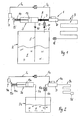
- a microdosing device after Fig. 1 serves to disperse liquid media in small quantities and with high precision.
- a microdosing for medical indications for dispensing pharmaceutical liquids is provided.
- the microdosing device can also be used for other purposes.
- the micro-metering device has a metering chamber D, which is open towards the environment to one side via a multiplicity of microscopically small discharge openings and is provided on a side remote from the discharge side with a boundary surface to which a vibration unit is assigned.
- the vibration unit is preferably designed as a piezoelectric element and can be set in vibration by electrical or electronic control means such that the boundary surface of the dosing chamber vibrates.
- a pre-metering chamber 9 is connected, which communicates with the dosing chamber D and is designed as a capillary.
- the pre-metering chamber 9 is open on its side facing away from the dosing D. The open area is provided with a microbiological filter unit 16 so as to allow pressure equalization with the environment while preventing contaminated air from entering the pre-metering chamber 9.
- the metering chamber D is connected to a flow channel 7 on a side facing away from the predosing chamber 9, which is connected to a medium reservoir 2 via a branched return channel 6, which likewise constitutes a flow channel.
- the flow cross section of the flow channel 7 is greater by a multiple than the flow cross section of the return channel. 6
- the medium reservoir 2 stores a liquid F serving as a medium in a hermetically sealed state.
- a suction channel serving flow channel 5 Into the medium reservoir 2 projects as a suction channel serving flow channel 5, whose open intake is located below the liquid level of the liquid F and thus permanently immersed in the liquid F, as long as the medium reservoir 2 is not substantially empty.
- the intake passage 5 is connected to a conveying device 3 serving as a filling device, which is designed as a manually operable thrust piston pump.
- the conveyor 3 has a working piston 13 which is mounted linearly displaceable in a corresponding working cylinder. By a displacement of the working piston, the volume of a cylinder chamber of the working cylinder is changed in a basically known manner.
- a piston rod of the working piston 13 protrudes from the working cylinder and is provided at its outer front end with a stop block 15 on which a return spring assembly 14 is supported.
- the return spring arrangement 14 serves to return the working piston 13 to a starting position after a corresponding functional stroke.
- a sensor 4 in the present case in the form of a limit switch assigned, which is connected by means of a signal line S 1 to an electrical or electronic control unit S.
- the control unit S controls the activation or deactivation of the vibration unit by means of a control line S 2 .
- the intake passage 5 is associated with a check valve 10 which opens in the direction of the cylinder chamber and prevents liquid already in the cylinder space of the delivery device 3 from flowing back into the medium reservoir 2.
- the flow channel 7 is associated with a check valve 8, which opens to the dosing D out, to prevent liquid from the flow channel 7 and from the dosing D can flow back into the cylinder chamber of the conveyor 3.
- the return channel 6 is provided with a check valve 11 opening towards the medium reservoir 2.
- the check valve 11 serves to close the return channel 6 as soon as the pressure in the medium reservoir 2 is higher than in the flow channel 7.
- the check valve 11 is preceded by a filter device 12, which is thus arranged on the return suction channel 6 between the flow channel 7 and check valve 11.
- the filter device 12 constitutes a microbiological filter. This prevents contaminated fluid from flowing back from the metering chamber D and from the flow channel 7 into the medium reservoir 2. The contaminating components remain suspended in the filter device 12.
- the described arrangement ensures that the liquid F remains clean and thus uncontaminated in the medium reservoir 2.
- liquid F is first introduced into the cylinder chamber via the intake channel 5 the conveyor 3 sucked by the working piston 13 performs a corresponding stroke.
- This can be referred to as a priming process. It makes sense that despite appropriate detection of the corresponding function stroke by the limit switch of the sensor 4 during this initial filling no control process for the vibration unit.
- the metering space D and the predosing chamber 9 can now be filled in a next stroke or in several strokes.
- the working piston 13 is manually pressed in the direction of the flow channel 7, whereby the corresponding flow pressure opens the check valve 8 and the liquid flows into the dosing chamber D and the pre-metering chamber 9.
- a working stroke of the working piston 13 and thus the volume of the cylinder chamber is adjusted to the filling volume of the dosing D and the predosing 9, that with a single stroke of the working piston 13, a sufficient filling of the dosing D and the predosing 9 occurs.
- the check valve 10 of the intake passage 5 Due to the pressure build-up within the cylinder space, the check valve 10 of the intake passage 5 is necessarily closed, so that no liquid can be pushed back into the medium reservoir 2. Since the flow cross sections of the flow channel 7 and the return channel 6 differ greatly, as stated above, in addition, the flow resistance within the return channel 6 is so large that the liquid is pressed into the dosing chamber D, without diverting a partial flow in the return channel 6.
- control unit S includes intelligent electronics, correspondingly different control programs can be programmed and executed here.
- superfluous liquid in the flow channel 7 can flow through the return channel 6 into the medium reservoir 2.
- the medium reservoir 2 is designed as a closed pressure vessel, upon removal of fluid F from the medium reservoir 2 inevitably creates a negative pressure that can cause a corresponding suction pressure to open the check valve 11 of the return channel 6 and so excess liquid from the flow channel 7 as well from the dosing chamber D and the pre-metering 9 in the medium reservoir 2 to suck back. This is advantageous, in particular, if no complete emptying of the metering space D and / or the predosing chamber has taken place during a corresponding discharge operation by the vibration unit.
- a flow channel 6a is provided which connects the medium reservoir 2a with the dosing space D and is designed as an intake channel for the liquid F.
- the intake passage 6a projects analogously to the intake passage 5 of the Fig. 1 into the liquid F.
- the conveying device 3a is connected to the medium reservoir 2a via a pressure channel 5a only in the manner of a pressure vessel, in that the corresponding pressure channel 5a protrudes only into the upper region of the medium reservoir 2a, without necessarily coming into contact with the fluid F.
- a preferably manual loading of the piston 13a leads to a linear piston movement, which reduces the cylinder space and pressurizes the medium reservoir 2a via the pressure channel 5a.
- a corresponding build-up of pressure in the medium reservoir 2a leads to an overpressure in the medium reservoir, which presses the fluid F through the flow channel 6a into the metering chamber D and into the predosing chamber 9a.
- a preferably simultaneous activation of the vibration unit for discharging the liquid present in the dosing space D causes a desired emptying of the dosing space D and possibly the pre-metering chamber 9a.
- the pressure conditions should also be designed so that no permanent leakage of liquid takes place in the region of the discharge openings of the dosing space D.
- the Control unit S designed so that the vibration unit remains activated during the pressure load by the piston 13a.
- the return spring 14a returns the piston to the unloaded home position Fig. 2 back.
- a filter unit 12a is provided, which is preferably microbiologically effective. This holds back contaminations, so that the liquid in the medium reservoir remains pure.
- the provision of the piston 13a in the starting position causes a sensor signal of the sensor unit 4a, so that the vibration unit can be switched off via the control unit S.
Landscapes
- Health & Medical Sciences (AREA)
- Engineering & Computer Science (AREA)
- Life Sciences & Earth Sciences (AREA)
- Anesthesiology (AREA)
- General Health & Medical Sciences (AREA)
- Biomedical Technology (AREA)
- Heart & Thoracic Surgery (AREA)
- Hematology (AREA)
- Bioinformatics & Cheminformatics (AREA)
- Animal Behavior & Ethology (AREA)
- Pulmonology (AREA)
- Public Health (AREA)
- Veterinary Medicine (AREA)
- Biophysics (AREA)
- Basic Packing Technique (AREA)
- Infusion, Injection, And Reservoir Apparatuses (AREA)
- Loading And Unloading Of Fuel Tanks Or Ships (AREA)
- Pipeline Systems (AREA)
- Medical Preparation Storing Or Oral Administration Devices (AREA)
Description
- Die Erfindung betrifft eine Mikrodosiervorrichtung für ein flüssiges Medium mit einem Dosierraum sowie mit einer elektrisch oder elektronisch aktivierbaren Vibrationseinheit, die wenigstens eine Begrenzungsfläche des Dosierraumes für einen Austragvorgang eines Mediumvolumens in Schwingungen versetzen kann, sowie mit einem Mediumspeicher, der mittels wenigstens eines Strömungskanales mit dem Dosierraum verbunden ist.
- Eine derartige Mikrodosiervorrichtung ist aus der
DE 10 2004 006 452 A1 bekannt. Die bekannte Mikrodosiervorrichtung saugt durch entsprechende Druckdifferenzen und durch Kapillarwirkung das auszutragende Mediumvolumen aus einer als Kapillare ausgeführten Vorratskammer in den Dosierraum. Zudem ist eine Befüllungseinrichtung vorgesehen, die Flüssigkeit in die Vorratskammer und in die Dosierkammer fördert, um die Vorratskammer und die Dosierkammer zu befüllen. - Aufgabe der Erfindung ist es, eine Mikrodosiervorrichtung der eingangs genannten Art zu schaffen, die einfach handhabbar und zuverlässig dosierbar ist.
- Diese Aufgabe wird dadurch gelöst, dass dem wenigstens einen Strömungskanal eine manuell betätigbare Fördereinrichtung zum Zuführen von Medium in den Dosierraum und/oder zum Rückführen von Medium aus dem Dosierraum in den Mediumspeicher zugeordnet ist. Durch die erfindungsgemäße Lösung ist es für eine Bedienperson möglich, bei Bedarf den Dosierraum zu befüllen, um anschließend bei vollständig befülltem Dosierraum eine Applikation starten zu können. Dadurch ist eine zuverlässige und gleichbleibende Dosierung gewährleistet. Dies ist insbesondere bei pharmazeutischen und medizinisch wirksamen Medien vorteilhaft, um Über- oder Unterdosierungen bei einer entsprechenden Anwendung vermeiden zu können. Die Mediumzufuhr durch die Fördereinrichtung kann direkt oder indirekt erfolgen. Bei direkter Befüllung steht die Fördereinrichtung über einen Strömungskanal mit dem Dosierraum in Verbindung. Bei indirekter Befüllung dient die Fördereinrichtung dazu, indirekt - insbesondere durch Druckaufbau - auf das Medium derart einzuwirken, dass es von einem Mediumspeicher zu dem Dosierraum gefördert wird.
- In Ausgestaltung der Erfindung ist eine Sensorik vorgesehen, die einen Befüllungsvorgang durch die Fördereinrichtung erfasst und entsprechende Signale an eine Steuereinheit weiterleitet, die die Vibrationseinheit in Abhängigkeit von den entsprechenden Signalen der Sensorik zu- oder abschaltet. Dadurch ist gewährleistet, dass ein Ausbringen des Mediums im Dosierraum erst dann erfolgt, wenn der Dosierraum vollständig befüllt ist. Sensiert wird nicht der Befüllungszustand des Dosierraumes, sondern vielmehr der Befüllungsvorgang durch die Fördereinrichtung. In vorteilhafter Weise umfasst die Sensorik wenigstens einen Wegsensor, der die Anfangs- und/oder Endpunkte eines Bewegungsvorganges der insbesondere mechanischen Fördereinrichtung erfasst. Falls die Befüllung durch die Fördereinrichtung indirekt über Druckbeaufschlagung erfolgt, wird die Druckbeaufschlagung sensiert. Statt eines Wegsensors kann insbesondere auch ein Drucksensor vorgesehen sein.
- In weiterer Ausgestaltung der Erfindung umfasst die manuell betätigbare Fördereinrichtung eine mechanische Kolbenpumpe. Die Kolbenpumpe wird für einen entsprechenden Arbeitshub manuell durch eine Bedienperson betätigt. Ein Rückhub in die Ausgangslage erfolgt vorzugsweise durch Federkraft. Es ist aber auch möglich, bei der mechanischen Kolbenpumpe lediglich die Einleitung des Hubvorganges manuell zu starten und anschließend den Arbeitshub durch eine vorgespannte Federeinheit federbetätigt ablaufen zu lassen. Eine weitere Federeinheit kann dann für den Rückhub verantwortlich sein. Hierdurch wird benutzerunabhängig immer eine gleichbleibende Befüllung des Dosierraumes erreicht.
- Falls dem Dosierraum zusätzlich eine insbesondere als Kapillare ausgebildete Vordosierkammer zugeordnet ist, ist das Fördervolumen der manuell betätigbaren, mechanischen Fördereinrichtung vorteilhaft so bemessen, dass mit einem einzigen Arbeitshub sowohl der Dosierraum als auch die Vordosierkammer befüllt werden können.
- ln weiterer Ausgestaltung der Erfindung ist wenigstens ein Strömungskanal zwischen dem Dosierraum und dem Mediumspeicher und/oder zwischen dem Dosierraum und der Fördereinrichtung und/oder zwischen der Fördereinrichtung und dem Mediumspeicher mit wenigstens einer Ventilanordnung versehen. Dadurch ist gewährleistet, dass Fehlströmungen des Mediums vermieden werden. Hierdurch ist insbesondere eine Vermischung von im Bereich des Dosierraumes bereits mit Umgebungsluft in Kontakt geratenem, kontaminiertem Medium mit noch unkontaminiertem Medium aus dem Mediumspeicher vermeidbar.
- In weiterer Ausgestaltung der Erfindung öffnet oder schließt die Ventilanordnung druckabhängig. In weiterer Ausgestaltung ist die Ventilanordnung als mechanisches Rückschlagventil ausgeführt. Dadurch wird eine ungewünschte Rückströmung oder Rücksaugung von Medium entgegen der gewünschten Strömungsrichtung vermieden.
- In weiterer Ausgestaltung der Erfindung ist der Strömungskanal zwischen dem Mediumspeicher und dem Dosierraum mit einer Filtereinrichtung, insbesondere einer mikrobiologischen Filtereinrichtung, versehen. Dadurch ist gewährleistet, dass kein kontaminiertes Medium über den Strömungskanal in den Mediumspeicher eintreten kann. Das Medium im Mediumspeicher selbst, vorzugsweise eine entsprechende pharmazeutische Flüssigkeit, ist mikrobiologisch rein. Der Mediumspeicher ist derart dicht ausgeführt, dass keine Umgebungsgase in den Mediumspeicher eintreten können.
- Weitere Vorteile und Merkmale der Erfindung ergeben sich aus den Ansprüchen sowie aus der nachfolgenden Beschreibung bevorzugter Ausführungsbeispiele der Erfindung, die anhand der Zeichnungen dargestellt sind.
- Fig. 1
- zeigt schematisch eine Ausführungsform einer erfindungsgemäßen Mikrodosiervorrichtung, bei der eine direkte Befüllung eines Dosierraumes durch eine mechanische Fördereinrichtung erfolgt und
- Fig. 2
- eine weitere Ausführungsform einer Mikrodosiervorrichtung: die nicht Teil der in Ansprüche 1-2 definierter Erfindung ist, bei der eine indirekte Befüllung des Dosierraumes über eine Druckbeaufschlagung eines Mediumspeichers erfolgt.
- Eine Mikrodosiervorrichtung nach
Fig. 1 dient dazu, flüssige Medien in geringen Mengen und hochgenau dosiert auszubringen. In besonders vorteilhafter Weise ist eine derartige Mikrodosiervorrichtung für medizinische Indikationen zum Ausbringen pharmazeutischer Flüssigkeiten vorgesehen. In gleicher Weise kann die Mikrodosiervorrichtung aber auch für andere Einsatzzwecke eingesetzt werden. Zur hochgenauen Dosierung weist die Mikrodosiervorrichtung einen Dosierraum D auf, der zu einer Seite hin über eine Vielzahl mikroskopisch kleiner Austragöffnungen zur Umgebung hin offen ist und an einer von der Austragseite abliegenden Seite mit einer Begrenzungsfläche versehen ist, der eine Vibrationseinheit zugeordnet ist. Die Vibrationseinheit ist vorzugsweise als Piezoelement ausgeführt und durch elektrische oder elektronische Steuermittel derart in Schwingungen versetzbar, dass die Begrenzungsfläche des Dosierraumes vibriert. Diese Vibrationen führen dazu, dass über entsprechende Kapillarkräfte das im Dosierraum befindliche, flüssige Medium durch die mikroskopisch kleinen Austragöffnungen hindurch zur Umgebung hin austritt. An den auch als Dosierkammer bezeichneten Dosierraum D ist eine Vordosierkammer 9 angeschlossen, die kommunizierend mit dem Dosierraum D in Verbindung steht und als Kapillare ausgeführt ist. Die Vordosierkammer 9 ist auf ihrer dem Dosierraum D abgewandten Endseite offen. Der offene Bereich ist mit einer mikrobiologischen Filtereinheit 16 versehen, um so einen Druckausgleich mit der Umgebung zu ermöglichen, gleichzeitig aber zu verhindern, dass kontaminierte Luft in die Vordosierkammer 9 gelangen kann. - Der grundsätzliche Aufbau der durch die Vibrationseinheit, den Dosierraum D, die Austragöffnungen und die Vordosierkammer gebildeten Austrageinheit entspricht der aus der
DE 10 2004 006 452 A1 bekannten Baueinheit, so dass bezüglich weiterer Details ergänzend auf den Inhalt dieser Druckschrift verwiesen wird. - Um den Dosierraum D und die Vordosierkammer 9 befüllen zu können, ist der Dosierraum D auf einer der Vordosierkammer 9 abgewandten Seite mit einem Strömungskanal 7 verbunden, der über einen abgezweigten Rücklaufkanal 6, der ebenfalls einen Strömungskanal darstellt, an einen Mediumspeicher 2 angeschlossen ist. Der Strömungsquerschnitt des Strömungskanales 7 ist um ein Vielfaches größer als der Strömungsquerschnitt des Rücklaufkanales 6.
- Der Mediumspeicher 2 speichert eine als Medium dienende Flüssigkeit F in hermetisch abgedichteten Zustand. In den Mediumspeicher 2 ragt ein als Ansaugkanal dienender Strömungskanal 5 hinein, dessen offener Ansaugstutzen unterhalb des Flüssigkeitsstandes der Flüssigkeit F angeordnet ist und somit permanent in die Flüssigkeit F eingetaucht ist, solange der Mediumspeicher 2 nicht im wesentlichen leer ist. Der Ansaugkanal 5 ist mit einer als Befüllungseinrichtung dienenden Fördereinrichtung 3 verbunden, die als manuell betätigbare Schubkolbenpumpe ausgebildet ist. Die Fördereinrichtung 3 weist einen Arbeitskolben 13 auf, der in einem entsprechenden Arbeitszylinder linear verschiebbar gelagert ist. Durch eine Verschiebung des Arbeitskolbens wird das Volumen eines Zylinderraumes des Arbeitszylinders in grundsätzlich bekannter Weise verändert. An den Zylinderraum des Arbeitszylinders schließt der Strömungskanal 7 an, der zu dem Dosierraum D führt. Zudem ist der Zylinderraum auch mit dem Ansaugkanal 5 verbunden, der in den Mediumspeicher 2 mündet. Eine Kolbenstange des Arbeitskolbens 13 ragt aus dem Arbeitszylinder hinaus und ist an ihrem außenliegenden Stirnende mit einem Anschlagblock 15 versehen, an dem sich eine Rückstellfederanordnung 14 abstützt. Die Rückstellfederanordnung 14 dient dazu, den Arbeitskolben 13 nach einem entsprechenden Funktionshub in eine Ausgangslage zurückzustellen.
- Um eine Bewegung des Arbeitskolbens 13 aus seiner Ausgangslage gemäß
Fig. 1 heraus oder in die Ausgangslage zurück zu erfassen, ist dem Anschlagblock 15 eine Sensorik 4, vorliegend in Form eines Endschalters, zugeordnet, der mittels einer Signalleitung S1 an eine elektrische oder elektronische Steuereinheit S angeschlossen ist. Die Steuereinheit S steuert mittels einer Steuerleitung S2 die Aktivierung oder Deaktivierung der Vibrationseinheit. - Dem Ansaugkanal 5 ist ein in Richtung des Zylinderraumes öffnendes Rückschlagventil 10 zugeordnet, das verhindert, dass bereits im Zylinderraum der Fördereinrichtung 3 befindliche Flüssigkeit in den Mediumspeicher 2 zurückfließen kann. Auch dem Strömungskanal 7 ist ein Rückschlagventil 8 zugeordnet, das zum Dosierraum D hin öffnet, um zu verhindern, dass Flüssigkeit aus dem Strömungskanal 7 und aus dem Dosierraum D zurück in den Zylinderraum der Fördereinrichtung 3 fließen kann. Schließlich ist auch der Rücklaufkanal 6 mit einem zum Mediumspeicher 2 hin öffnenden Rückschlagventil 11 versehen. Das Rückschlagventil 11 dient dazu, den Rücklaufkanal 6 zu schließen, sobald der Druck im Mediumspeicher 2 höher ist als im Strömungskanal 7. Dem Rückschlagventil 11 ist eine Filtereinrichtung 12 vorgeschaltet, die somit am Rücksaugkanal 6 zwischen Strömungskanal 7 und Rückschlagventil 11 angeordnet ist. Die Filtereinrichtung 12 stellt einen mikrobiologischen Filter dar. Dadurch wird verhindert, dass kontaminierte Flüssigkeit aus dem Dosierraum D und vom Strömungskanal 7 in den Mediumspeicher 2 zurückfließen kann. Die kontaminierenden Bestandteile bleiben in der Filtereinrichtung 12 hängen.
- Durch die beschriebene Anordnung ist gewährleistet, dass die Flüssigkeit F im Mediumspeicher 2 rein und damit unkontaminiert bleibt.
- Die Arbeitsweise der Mikrodosiervorrichtung nach
Fig. 1 ist wie folgt: - Um den Dosierraum D und die Vordosierkammer 9 mit Flüssigkeit F zu füllen, wird zunächst über den Ansaugkanal 5 Flüssigkeit F in den Zylinderraum der Fördereinrichtung 3 angesaugt, indem der Arbeitskolben 13 einen entsprechenden Hub vollführt. Diese Erstbefüllung des Zylinderraumes kann als Priming-Vorgang bezeichnet werden. Es ist sinnvoll, dass trotz entsprechender Erfassung des entsprechenden Funktionshubes durch den Endschalter der Sensorik 4 während dieser Erstbefüllung kein Steuervorgang für die Vibrationseinheit erfolgt. Sobald der Zylinderraum befüllt ist, kann nun in einem nächsten Hub oder in mehreren Hüben der Dosierraum D und die Vordosierkammer 9 befüllt werden. Hierzu wird der Arbeitskolben 13 manuell in Richtung des Strömungskanales 7 gedrückt, wodurch der entsprechende Strömungsdruck das Rückschlagventil 8 öffnet und die Flüssigkeit in den Dosierraum D und die Vordosierkammer 9 strömt. Vorzugsweise ist ein Arbeitshub des Arbeitskolbens 13 und damit das Volumen des Zylinderraumes derart auf das Befüllungsvolumen des Dosierraumes D und der Vordosierkammer 9 abgestimmt, dass mit einem einzigen Hub des Arbeitskolbens 13 eine ausreichende Befüllung des Dosierraumes D und der Vordosierkammer 9 erfolgt. Durch den Druckaufbau innerhalb des Zylinderraumes wird zwangsläufig das Rückschlagventil 10 des Ansaugkanales 5 geschlossen, so dass keine Flüssigkeit in den Mediumspeicher 2 zurückgedrückt werden kann. Da die Strömungsquerschnitte des Strömungskanales 7 und des Rücklaufkanales 6 sich stark unterscheiden, wie oben ausgeführt wurde, ist zudem der Strömungswiderstand innerhalb des Rücklaufkanales 6 so groß, dass die Flüssigkeit in den Dosierraum D gedrückt wird, ohne einen Teilstrom in den Rücklaufkanal 6 abzuleiten.
- Bei einem entsprechenden Rückhub des Arbeitskolbens 13 wird zwangsläufig bereits wieder Flüssigkeit F in den Zylinderraum gesaugt. Da das Rückschlagventil 8 des Strömungskanales 7 bei dem entsprechenden Rückhub, der nach Wegfall der manuellen Belastung durch die Rückstellkraft der Rückstellfederanordnung 14 erfolgt, geschlossen wird, kann keine Flüssigkeit mehr aus dem Dosierraum D oder aus dem Strömungskanal 7 zurückgesaugt werden. Nach den beschriebenen Hüben des Arbeitskolbens 13 sind nun der Dosierraum D und die Vordosierkammer 9 wie auch der Zylinderraum der Fördereinrichtung 3 befüllt. Sobald nun manuell ein erneuter Arbeitshub des Arbeitskolbens 13 eingeleitet wird, wird gleichzeitig mit der Einleitung der Kolbenbewegung über die Steuereinheit S die Vibrationseinheit aktiviert, so dass ein Austragvorgang erfolgt. Sobald der Anschlagblock 15 bei einem anschließenden Rückhub des Arbeitskolbens 13 wieder an dem Endschalter anschlägt, kann die Vibrationseinheit deaktiviert werden.
- Es ist aber auch möglich, andere Ansteuerungsvorgänge der Vibrationseinheit durch die Steuereinheit S abhängig von entsprechenden Signalen der Sensorik vorzusehen. Falls die Steuereinheit S eine intelligente Elektronik umfasst, können hier entsprechend unterschiedliche Ansteuerprogramme einprogrammiert und ausgeführt werden. Insbesondere überflüssige Flüssigkeit im Strömungskanal 7 kann durch den Rücklaufkanal 6 in den Mediumspeicher 2 abfließen. Falls der Mediumspeicher 2 als geschlossener Druckbehälter gestaltet ist, entsteht bei Entnahme von Flüssigkeit F aus dem Mediumspeicher 2 zwangsläufig ein Unterdruck, der einen entsprechenden Ansaugdruck bewirken kann, um das Rückschlagventil 11 des Rücklaufkanales 6 zu öffnen und so überschüssige Flüssigkeit aus dem Strömungskanal 7 wie auch aus dem Dosierraum D und der Vordosierkammer 9 in den Mediumspeicher 2 zurückzusaugen. Dies ist insbesondere dann vorteilhaft, wenn bei einem entsprechenden Austragvorgang durch die Vibrationseinheit keine vollständige Entleerung des Dosierraumes D und/oder der Vordosierkammer erfolgt ist.
- Vom grundsätzlichen Aufbau, wie z.B. aus der
GB 1575887 A Fig. 2 der Mikrodosiervorrichtung nachFig. 1 , so dass ergänzend auf die Offenbarung der Ausführungsform nachFig. 1 verwiesen wird. Funktionsgleiche Teile und Baueinheiten sind mit den gleichen Bezugszeichen wie bei der Ausführungsform nachFig. 1 , jedoch unter Hinzufügung des Buchstabens a versehen. Wesentlicher Unterschied bei der Ausführungsform nachFig. 2 ist es, dass dort keine direkte Befüllung des Dosierraumes D und der Vordosierkammer 9a durch die Fördereinrichtung 3a erfolgt, sondern vielmehr eine indirekte Befüllung über entsprechende Druckbeaufschlagung des druckdichten Mediumspeichers 2a stattfindet. Hierzu ist ein Strömungskanal 6a vorgesehen, der den Mediumspeicher 2a mit dem Dosierraum D verbindet und als Ansaugkanal für die Flüssigkeit F gestaltet ist. Der Ansaugkanal 6a ragt analog dem Ansaugkanal 5 derFig. 1 in die Flüssigkeit F hinein. Die Fördereinrichtung 3a hingegen ist über einen Druckkanal 5a lediglich nach Art eines Druckbehälters mit dem Mediumspeicher 2a verbunden, indem der entsprechende Druckkanal 5a lediglich in den oberen Bereich des Mediumspeichers 2a hineinragt, ohne zwangsläufig mit der Flüssigkeit F in Kontakt zu geraten. - Eine vorzugsweise manuelle Belastung des Kolbens 13a führt zu einer linearen Kolbenbewegung, die den Zylinderraum verkleinert und über den Druckkanal 5a den Mediumspeicher 2a unter Druck setzt.
- Ein entsprechender Druckaufbau im Mediumspeicher 2a führt im Mediumspeicher zu einem Überdruck, der die Flüssigkeit F durch den Strömungskanal 6a in den Dosierraum D und in die Vordosierkammer 9a drückt. Eine vorzugsweise gleichzeitige Aktivierung der Vibrationseinheit zum Austragen der im Dosierraum D befindlichen Flüssigkeit bewirkt eine gewünschte Entleerung des Dosierraumes D und gegebenenfalls der Vordosierkammer 9a. Vorteilhaft sollten die Druckverhältnisse auch so gestaltet sein, dass kein permanentes Auslaufen von Flüssigkeit im Bereich der Austragöffnungen des Dosierraumes D erfolgt.
- Während des Austragvorganges von Medium aus dem Dosierraum D zur Umgebung muss der Kolben 13a gegen die Rückstellkraft der Rückholfeder 14a gedrückt gehalten bleiben. In vorteilhafter Weise ist die Steuereinheit S so gestaltet, dass die Vibrationseinheit während der Druckbelastung durch den Kolben 13a aktiviert bleibt. Sobald die Belastung des Kolbens 13a entfernt wird, vorzugsweise durch Wegnahme der manuellen Belastung, stellt die Rückholfeder 14a den Kolben wieder in die unbelastete Ausgangslage gemäß
Fig. 2 zurück. Dadurch entsteht aufgrund der miteinander kommunizierenden Räume, nämlich dem Zylinderraum und dem Raum im Mediumspeicher 2a, im Mediumspeicher 2a ein Unterdruck, der ein Rücksaugen von im Dosierraum D verbliebenen Mediumresten bewirkt. Um zu verhindern, dass Kontaminationen aus dem Dosierraum in den Mediumspeicher gelangen, ist eine Filtereinheit 12a vorgesehen, die vorzugsweise mikrobiologisch wirksam ist. Diese hält Kontaminationen zurück, so dass die Flüssigkeit im Mediumspeicher rein bleibt. Die Rückstellung des Kolbens 13a in die Ausgangslage bewirkt ein Sensorsignal der Sensoreinheit 4a, so dass die Vibrationseinheit über die Steuereinheit S abgeschaltet werden kann.
Claims (2)
- Mikrodosiervorrichtung für ein flüssiges Medium mit einem Dosierraum (D) sowie mit einer elektrisch oder elektronisch aktivierbaren Vibrationseinheit (S), die wenigstens eine Begrenzungsfläche des Dosierraumes (D) für einen Austragvorgang eines Mediumvolumens in Schwingungen versetzen kann, sowie mit einem insbesondere druckdichten Mediumspeicher (2), der mittels wenigstens eines Strömungskanales mit dem Dosierraum (D) verbunden ist,
dadurch gekennzeichnet, dass
dem Strömungskanal (5, 7) eine manuell betätigbare Kolbenpumpe (3) zum Zuführen von Medium in den Dosierraum (D) zugeordnet ist, wobei in dem Strömungskanal (7) zwischen der Kolbenpumpe (3) und dem Dosierraum (D) ein mechanisches Rückschlagventil (8) vorgesehen ist, welches den Rückfluss von kontaminiertem Medium aus dem Dosierraum (D) in die Kolbenpumpe (3) verhindert, und wobei vom Strömungskanal (7), der zwischen Kolbenpumpe (3) und Dosierraum (D) verläuft, zwischen dem Rückschlagventil (8) und dem Dosierraum (D) ein weiterer Strömungskanal (6) zum Mediumspeicher (2) abzweigt, der mit einer Filtereinrichtung (12) versehen ist. - Mikrodosiervorrichtung nach Anspruch 1, dadurch gekennzeichnet, dass eine Sensorik (4) vorgesehen ist, die einen Befüllungsvorgang durch die Fördereinrichtung (3) erfasst und entsprechende Signale an eine Steuereinheit (S) weiterleitet, die die Vibrationseinheit in Abhängigkeit von entsprechenden Signalen der Sensorik zu- oder abschaltet.
Applications Claiming Priority (1)
| Application Number | Priority Date | Filing Date | Title |
|---|---|---|---|
| DE200610047658 DE102006047658B4 (de) | 2006-09-29 | 2006-09-29 | Mikrodosiervorrichtung für ein flüssiges Medium |
Publications (2)
| Publication Number | Publication Date |
|---|---|
| EP1905469A1 EP1905469A1 (de) | 2008-04-02 |
| EP1905469B1 true EP1905469B1 (de) | 2013-05-22 |
Family
ID=38787714
Family Applications (1)
| Application Number | Title | Priority Date | Filing Date |
|---|---|---|---|
| EP20070018051 Not-in-force EP1905469B1 (de) | 2006-09-29 | 2007-09-14 | Mikrodosiervorrichtung für ein flüssiges Medium |
Country Status (4)
| Country | Link |
|---|---|
| US (1) | US7770757B2 (de) |
| EP (1) | EP1905469B1 (de) |
| JP (1) | JP2008089181A (de) |
| DE (1) | DE102006047658B4 (de) |
Families Citing this family (10)
| Publication number | Priority date | Publication date | Assignee | Title |
|---|---|---|---|---|
| FR2910253B1 (fr) * | 2006-12-20 | 2010-03-12 | Oreal | Procede de distribution d'un produit pulverise par un systeme de pulverisation piezoelectrique et systeme de pulverisation pour la mise en oeuvre d'un tel procede |
| US20090045216A1 (en) * | 2007-08-15 | 2009-02-19 | Mark Mamaghani | Portable fluid-storage container and method of use thereof |
| JP5731521B2 (ja) * | 2009-11-04 | 2015-06-10 | コーニンクレッカ フィリップス エヌ ヴェ | 薬剤計量システムを含む医薬供給装置 |
| DE102010024913A1 (de) * | 2010-06-15 | 2011-12-15 | Ing. Erich Pfeiffer Gmbh | Zerstäubervorrichtung |
| US8753315B2 (en) * | 2011-02-17 | 2014-06-17 | Calibra Medical, Inc. | Manual basal bolus drug delivery device |
| CN105764616A (zh) | 2013-09-09 | 2016-07-13 | 奥姆纽斯特有限责任公司 | 喷雾装置 |
| EP3731894A1 (de) | 2017-12-28 | 2020-11-04 | Sanofi | Verpackungsanordnung |
| GB2578127B (en) * | 2018-10-17 | 2022-11-23 | Vectair Systems Ltd | Fluid dispenser |
| US20240083797A1 (en) * | 2022-07-27 | 2024-03-14 | Core Pacific Inc. | Micro-dosing system for use with a water mineralization process |
| DE102023135959A1 (de) * | 2023-12-20 | 2025-06-26 | Festo Se & Co. Kg | Verfahren zum Dosieren einer Flüssigkeitsmenge und Pipette zum Dosieren einer Flüssigkeitsmenge |
Family Cites Families (12)
| Publication number | Priority date | Publication date | Assignee | Title |
|---|---|---|---|---|
| DE2724175C3 (de) * | 1977-05-27 | 1979-11-15 | Bosch-Siemens Hausgeraete Gmbh, 7000 Stuttgart | Inhalationsgerät zur Behandlung der Atemwege |
| DE2726370C2 (de) * | 1977-06-10 | 1981-09-24 | Basf Ag, 6700 Ludwigshafen | Meßverfahren und Meßeinrichtung zur Bestimmung der Homogenität von Magnetdispersionen |
| DE2812233A1 (de) * | 1978-03-21 | 1979-10-04 | Bosch Gmbh Robert | Einrichtung zur erfassung der von einer fluessigkeitsfoerdereinrichtung gefoerderten fluessigkeitsmenge |
| EP0739654A3 (de) * | 1992-05-13 | 1997-01-02 | Siemens Ag | Zerstäubungsgerät, insbesondere Taschen-Zerstäubungsgerät |
| DE9422442U1 (de) * | 1993-11-04 | 2002-07-25 | BRAND GMBH + CO KG, 97877 Wertheim | Dispenser |
| US5758637A (en) | 1995-08-31 | 1998-06-02 | Aerogen, Inc. | Liquid dispensing apparatus and methods |
| DE19536623C1 (de) * | 1995-09-30 | 1996-10-02 | Bayerische Motoren Werke Ag | Verfahren und Vorrichtung zum Dosieren von Dickstoffen |
| CN1781559A (zh) * | 2000-10-05 | 2006-06-07 | 欧姆龙健康医疗事业株式会社 | 液体雾化装置 |
| DE10102152C1 (de) | 2001-01-18 | 2002-06-20 | Roland Zengerle | Vorrichtung und Verfahren zum Dosieren kleiner Flüssigkeitsmengen |
| JP2003175102A (ja) * | 2002-11-22 | 2003-06-24 | Matsushita Ecology Systems Co Ltd | 肺胞到達液粒子発生方法及びそれを利用した治療器 |
| EP1502606A1 (de) * | 2003-07-29 | 2005-02-02 | Polyspray sprl | Vorrichtung und Verfahren zum Zerstäuben einer Flüssigkeit |
| DE102004006452B4 (de) * | 2004-02-05 | 2006-04-20 | Ing. Erich Pfeiffer Gmbh | Mikrodosiervorrichtung |
-
2006
- 2006-09-29 DE DE200610047658 patent/DE102006047658B4/de not_active Expired - Fee Related
-
2007
- 2007-09-14 EP EP20070018051 patent/EP1905469B1/de not_active Not-in-force
- 2007-09-27 JP JP2007251345A patent/JP2008089181A/ja active Pending
- 2007-09-28 US US11/906,047 patent/US7770757B2/en not_active Expired - Fee Related
Also Published As
| Publication number | Publication date |
|---|---|
| EP1905469A1 (de) | 2008-04-02 |
| US20080078783A1 (en) | 2008-04-03 |
| US7770757B2 (en) | 2010-08-10 |
| DE102006047658B4 (de) | 2009-03-19 |
| JP2008089181A (ja) | 2008-04-17 |
| DE102006047658A1 (de) | 2008-04-03 |
Similar Documents
| Publication | Publication Date | Title |
|---|---|---|
| EP1905469A1 (de) | Mikrodosiervorrichtung für ein flüssiges Medium | |
| DE102012209314B4 (de) | Vorrichtung und Verfahren zur Abgabe oder Aufnahme eines Flüssigkeitsvolumens | |
| DE2557961C3 (de) | Flüssigkeitspumpsystem für einen Flüssigkeitsstrahlschreiber | |
| DE2638659B1 (de) | Mit der hand zu haltende pumppipette | |
| EP3551343B1 (de) | Pumpe und abgabevorrichtung | |
| EP2634112A1 (de) | Wiederbefüllbarer Ausgabebehälter | |
| EP3661566A1 (de) | Dekontaminationsanordnung, system sowie dekontaminationsverfahren | |
| EP2368041B1 (de) | Dosierpumpe mit vorrichtung zur entgasung des förderraums | |
| DE102011054404A1 (de) | Spender | |
| DE19906409A1 (de) | Dosiervorrichtung sowie Verfahren zum Betreiben einer Dosiervorrichtung | |
| DE3101020C2 (de) | Portionenspender für flüssiges Medium z. B. Seife | |
| DE102020121665A1 (de) | Dosiersystem mit einer Spritze und einer Spritzenpumpe | |
| DE102007010412B4 (de) | Vorrichtung und Verfahren zum Dosieren von Flüssigkeiten in gasgefüllte Räume | |
| DE102016109536A1 (de) | Kapillarentleerungshilfe | |
| DE3342384A1 (de) | Waschanlage zur scheibenreinigung von kraftfahrzeugen | |
| EP2419162B1 (de) | Flüssigkeitspumpengerät | |
| DE102016103943A1 (de) | Feuchtreinigungsgerät mit einer Pumpe zum Fördern von Flüssigkeit aus einem Flüssigkeitstank zu einem Reinigungselement | |
| WO2018072782A1 (de) | Dosiervorrichtung und verfahren zu deren betrieb | |
| EP1607724B1 (de) | Dosierventil sowie Verwendung einer Vielzahl desselben | |
| DE202020104431U1 (de) | Pumpeinrichtung zum chargenweisen Ausgeben einer Flüssigkeit | |
| DE2953952C2 (de) | ||
| EP3195768A1 (de) | Vorrichtung zum entleeren einer getränkeausgabeleitung einer heissgetränke-zubereitungseinrichtung | |
| DE102022109048A1 (de) | Gasabscheidevorrichtung mit Ausgleichsbehälter für Analysegerät | |
| DE2931495A1 (de) | Dosiereinrichtung | |
| DE102005056172A1 (de) | Injektionsspritze |
Legal Events
| Date | Code | Title | Description |
|---|---|---|---|
| PUAI | Public reference made under article 153(3) epc to a published international application that has entered the european phase |
Free format text: ORIGINAL CODE: 0009012 |
|
| AK | Designated contracting states |
Kind code of ref document: A1 Designated state(s): AT BE BG CH CY CZ DE DK EE ES FI FR GB GR HU IE IS IT LI LT LU LV MC MT NL PL PT RO SE SI SK TR |
|
| AX | Request for extension of the european patent |
Extension state: AL BA HR MK YU |
|
| 17P | Request for examination filed |
Effective date: 20080918 |
|
| AKX | Designation fees paid |
Designated state(s): AT BE BG CH CY CZ DE DK EE ES FI FR GB GR HU IE IS IT LI LT LU LV MC MT NL PL PT RO SE SI SK TR |
|
| RAP1 | Party data changed (applicant data changed or rights of an application transferred) |
Owner name: APTAR RADOLFZELL GMBH |
|
| GRAP | Despatch of communication of intention to grant a patent |
Free format text: ORIGINAL CODE: EPIDOSNIGR1 |
|
| GRAS | Grant fee paid |
Free format text: ORIGINAL CODE: EPIDOSNIGR3 |
|
| GRAA | (expected) grant |
Free format text: ORIGINAL CODE: 0009210 |
|
| AK | Designated contracting states |
Kind code of ref document: B1 Designated state(s): AT BE BG CH CY CZ DE DK EE ES FI FR GB GR HU IE IS IT LI LT LU LV MC MT NL PL PT RO SE SI SK TR |
|
| REG | Reference to a national code |
Ref country code: GB Ref legal event code: FG4D Free format text: NOT ENGLISH |
|
| REG | Reference to a national code |
Ref country code: CH Ref legal event code: EP |
|
| REG | Reference to a national code |
Ref country code: AT Ref legal event code: REF Ref document number: 612871 Country of ref document: AT Kind code of ref document: T Effective date: 20130615 |
|
| REG | Reference to a national code |
Ref country code: IE Ref legal event code: FG4D Free format text: LANGUAGE OF EP DOCUMENT: GERMAN |
|
| REG | Reference to a national code |
Ref country code: DE Ref legal event code: R096 Ref document number: 502007011784 Country of ref document: DE Effective date: 20130718 |
|
| REG | Reference to a national code |
Ref country code: CH Ref legal event code: NV Representative=s name: WAGNER PATENT AG, CH |
|
| REG | Reference to a national code |
Ref country code: LT Ref legal event code: MG4D |
|
| PG25 | Lapsed in a contracting state [announced via postgrant information from national office to epo] |
Ref country code: FI Free format text: LAPSE BECAUSE OF FAILURE TO SUBMIT A TRANSLATION OF THE DESCRIPTION OR TO PAY THE FEE WITHIN THE PRESCRIBED TIME-LIMIT Effective date: 20130522 Ref country code: GR Free format text: LAPSE BECAUSE OF FAILURE TO SUBMIT A TRANSLATION OF THE DESCRIPTION OR TO PAY THE FEE WITHIN THE PRESCRIBED TIME-LIMIT Effective date: 20130823 Ref country code: PT Free format text: LAPSE BECAUSE OF FAILURE TO SUBMIT A TRANSLATION OF THE DESCRIPTION OR TO PAY THE FEE WITHIN THE PRESCRIBED TIME-LIMIT Effective date: 20130923 Ref country code: ES Free format text: LAPSE BECAUSE OF FAILURE TO SUBMIT A TRANSLATION OF THE DESCRIPTION OR TO PAY THE FEE WITHIN THE PRESCRIBED TIME-LIMIT Effective date: 20130902 Ref country code: SI Free format text: LAPSE BECAUSE OF FAILURE TO SUBMIT A TRANSLATION OF THE DESCRIPTION OR TO PAY THE FEE WITHIN THE PRESCRIBED TIME-LIMIT Effective date: 20130522 Ref country code: SE Free format text: LAPSE BECAUSE OF FAILURE TO SUBMIT A TRANSLATION OF THE DESCRIPTION OR TO PAY THE FEE WITHIN THE PRESCRIBED TIME-LIMIT Effective date: 20130522 Ref country code: LT Free format text: LAPSE BECAUSE OF FAILURE TO SUBMIT A TRANSLATION OF THE DESCRIPTION OR TO PAY THE FEE WITHIN THE PRESCRIBED TIME-LIMIT Effective date: 20130522 Ref country code: IS Free format text: LAPSE BECAUSE OF FAILURE TO SUBMIT A TRANSLATION OF THE DESCRIPTION OR TO PAY THE FEE WITHIN THE PRESCRIBED TIME-LIMIT Effective date: 20130922 |
|
| REG | Reference to a national code |
Ref country code: NL Ref legal event code: VDEP Effective date: 20130522 |
|
| PG25 | Lapsed in a contracting state [announced via postgrant information from national office to epo] |
Ref country code: BG Free format text: LAPSE BECAUSE OF FAILURE TO SUBMIT A TRANSLATION OF THE DESCRIPTION OR TO PAY THE FEE WITHIN THE PRESCRIBED TIME-LIMIT Effective date: 20130822 Ref country code: PL Free format text: LAPSE BECAUSE OF FAILURE TO SUBMIT A TRANSLATION OF THE DESCRIPTION OR TO PAY THE FEE WITHIN THE PRESCRIBED TIME-LIMIT Effective date: 20130522 |
|
| PG25 | Lapsed in a contracting state [announced via postgrant information from national office to epo] |
Ref country code: LV Free format text: LAPSE BECAUSE OF FAILURE TO SUBMIT A TRANSLATION OF THE DESCRIPTION OR TO PAY THE FEE WITHIN THE PRESCRIBED TIME-LIMIT Effective date: 20130522 |
|
| PG25 | Lapsed in a contracting state [announced via postgrant information from national office to epo] |
Ref country code: SK Free format text: LAPSE BECAUSE OF FAILURE TO SUBMIT A TRANSLATION OF THE DESCRIPTION OR TO PAY THE FEE WITHIN THE PRESCRIBED TIME-LIMIT Effective date: 20130522 Ref country code: CZ Free format text: LAPSE BECAUSE OF FAILURE TO SUBMIT A TRANSLATION OF THE DESCRIPTION OR TO PAY THE FEE WITHIN THE PRESCRIBED TIME-LIMIT Effective date: 20130522 Ref country code: EE Free format text: LAPSE BECAUSE OF FAILURE TO SUBMIT A TRANSLATION OF THE DESCRIPTION OR TO PAY THE FEE WITHIN THE PRESCRIBED TIME-LIMIT Effective date: 20130522 Ref country code: DK Free format text: LAPSE BECAUSE OF FAILURE TO SUBMIT A TRANSLATION OF THE DESCRIPTION OR TO PAY THE FEE WITHIN THE PRESCRIBED TIME-LIMIT Effective date: 20130522 |
|
| PG25 | Lapsed in a contracting state [announced via postgrant information from national office to epo] |
Ref country code: NL Free format text: LAPSE BECAUSE OF FAILURE TO SUBMIT A TRANSLATION OF THE DESCRIPTION OR TO PAY THE FEE WITHIN THE PRESCRIBED TIME-LIMIT Effective date: 20130522 Ref country code: RO Free format text: LAPSE BECAUSE OF FAILURE TO SUBMIT A TRANSLATION OF THE DESCRIPTION OR TO PAY THE FEE WITHIN THE PRESCRIBED TIME-LIMIT Effective date: 20130522 |
|
| REG | Reference to a national code |
Ref country code: CH Ref legal event code: PCAR Free format text: NEW ADDRESS: BAECHERSTRASSE 9, 8832 WOLLERAU (CH) |
|
| PLBE | No opposition filed within time limit |
Free format text: ORIGINAL CODE: 0009261 |
|
| STAA | Information on the status of an ep patent application or granted ep patent |
Free format text: STATUS: NO OPPOSITION FILED WITHIN TIME LIMIT |
|
| BERE | Be: lapsed |
Owner name: APTAR RADOLFZELL G.M.B.H. Effective date: 20130930 |
|
| 26N | No opposition filed |
Effective date: 20140225 |
|
| PG25 | Lapsed in a contracting state [announced via postgrant information from national office to epo] |
Ref country code: MC Free format text: LAPSE BECAUSE OF FAILURE TO SUBMIT A TRANSLATION OF THE DESCRIPTION OR TO PAY THE FEE WITHIN THE PRESCRIBED TIME-LIMIT Effective date: 20130522 |
|
| REG | Reference to a national code |
Ref country code: DE Ref legal event code: R097 Ref document number: 502007011784 Country of ref document: DE Effective date: 20140225 |
|
| REG | Reference to a national code |
Ref country code: IE Ref legal event code: MM4A |
|
| PG25 | Lapsed in a contracting state [announced via postgrant information from national office to epo] |
Ref country code: IE Free format text: LAPSE BECAUSE OF NON-PAYMENT OF DUE FEES Effective date: 20130914 Ref country code: BE Free format text: LAPSE BECAUSE OF NON-PAYMENT OF DUE FEES Effective date: 20130930 |
|
| PGFP | Annual fee paid to national office [announced via postgrant information from national office to epo] |
Ref country code: CH Payment date: 20140922 Year of fee payment: 8 |
|
| REG | Reference to a national code |
Ref country code: AT Ref legal event code: MM01 Ref document number: 612871 Country of ref document: AT Kind code of ref document: T Effective date: 20130914 |
|
| PG25 | Lapsed in a contracting state [announced via postgrant information from national office to epo] |
Ref country code: AT Free format text: LAPSE BECAUSE OF NON-PAYMENT OF DUE FEES Effective date: 20130914 |
|
| PG25 | Lapsed in a contracting state [announced via postgrant information from national office to epo] |
Ref country code: MT Free format text: LAPSE BECAUSE OF FAILURE TO SUBMIT A TRANSLATION OF THE DESCRIPTION OR TO PAY THE FEE WITHIN THE PRESCRIBED TIME-LIMIT Effective date: 20130522 Ref country code: TR Free format text: LAPSE BECAUSE OF FAILURE TO SUBMIT A TRANSLATION OF THE DESCRIPTION OR TO PAY THE FEE WITHIN THE PRESCRIBED TIME-LIMIT Effective date: 20130522 Ref country code: CY Free format text: LAPSE BECAUSE OF FAILURE TO SUBMIT A TRANSLATION OF THE DESCRIPTION OR TO PAY THE FEE WITHIN THE PRESCRIBED TIME-LIMIT Effective date: 20130522 |
|
| PG25 | Lapsed in a contracting state [announced via postgrant information from national office to epo] |
Ref country code: LU Free format text: LAPSE BECAUSE OF NON-PAYMENT OF DUE FEES Effective date: 20130914 Ref country code: HU Free format text: LAPSE BECAUSE OF FAILURE TO SUBMIT A TRANSLATION OF THE DESCRIPTION OR TO PAY THE FEE WITHIN THE PRESCRIBED TIME-LIMIT; INVALID AB INITIO Effective date: 20070914 |
|
| REG | Reference to a national code |
Ref country code: DE Ref legal event code: R082 Ref document number: 502007011784 Country of ref document: DE Representative=s name: WITTE, WELLER & PARTNER PATENTANWAELTE MBB, DE Ref country code: DE Ref legal event code: R082 Ref document number: 502007011784 Country of ref document: DE Representative=s name: PATENTANWALTSKANZLEI CARTAGENA PARTNERSCHAFTSG, DE |
|
| REG | Reference to a national code |
Ref country code: CH Ref legal event code: PL |
|
| PG25 | Lapsed in a contracting state [announced via postgrant information from national office to epo] |
Ref country code: CH Free format text: LAPSE BECAUSE OF NON-PAYMENT OF DUE FEES Effective date: 20150930 Ref country code: LI Free format text: LAPSE BECAUSE OF NON-PAYMENT OF DUE FEES Effective date: 20150930 |
|
| REG | Reference to a national code |
Ref country code: FR Ref legal event code: PLFP Year of fee payment: 10 |
|
| REG | Reference to a national code |
Ref country code: FR Ref legal event code: PLFP Year of fee payment: 11 |
|
| REG | Reference to a national code |
Ref country code: FR Ref legal event code: PLFP Year of fee payment: 12 |
|
| PGFP | Annual fee paid to national office [announced via postgrant information from national office to epo] |
Ref country code: FR Payment date: 20210927 Year of fee payment: 15 Ref country code: IT Payment date: 20210930 Year of fee payment: 15 |
|
| PGFP | Annual fee paid to national office [announced via postgrant information from national office to epo] |
Ref country code: GB Payment date: 20210923 Year of fee payment: 15 Ref country code: DE Payment date: 20210922 Year of fee payment: 15 |
|
| REG | Reference to a national code |
Ref country code: DE Ref legal event code: R082 Ref document number: 502007011784 Country of ref document: DE Representative=s name: WITTE, WELLER & PARTNER PATENTANWAELTE MBB, DE |
|
| REG | Reference to a national code |
Ref country code: DE Ref legal event code: R119 Ref document number: 502007011784 Country of ref document: DE |
|
| GBPC | Gb: european patent ceased through non-payment of renewal fee |
Effective date: 20220914 |
|
| PG25 | Lapsed in a contracting state [announced via postgrant information from national office to epo] |
Ref country code: FR Free format text: LAPSE BECAUSE OF NON-PAYMENT OF DUE FEES Effective date: 20220930 Ref country code: DE Free format text: LAPSE BECAUSE OF NON-PAYMENT OF DUE FEES Effective date: 20230401 |
|
| PG25 | Lapsed in a contracting state [announced via postgrant information from national office to epo] |
Ref country code: IT Free format text: LAPSE BECAUSE OF NON-PAYMENT OF DUE FEES Effective date: 20220914 Ref country code: GB Free format text: LAPSE BECAUSE OF NON-PAYMENT OF DUE FEES Effective date: 20220914 |