EP1904698B1 - Aufsatzvorrichtung für einen schornstein - Google Patents
Aufsatzvorrichtung für einen schornstein Download PDFInfo
- Publication number
- EP1904698B1 EP1904698B1 EP06759530A EP06759530A EP1904698B1 EP 1904698 B1 EP1904698 B1 EP 1904698B1 EP 06759530 A EP06759530 A EP 06759530A EP 06759530 A EP06759530 A EP 06759530A EP 1904698 B1 EP1904698 B1 EP 1904698B1
- Authority
- EP
- European Patent Office
- Prior art keywords
- tubular housing
- chimney
- cap device
- set forth
- sidewalls
- Prior art date
- Legal status (The legal status is an assumption and is not a legal conclusion. Google has not performed a legal analysis and makes no representation as to the accuracy of the status listed.)
- Not-in-force
Links
- 239000002184 metal Substances 0.000 claims abstract description 30
- 229910052751 metal Inorganic materials 0.000 claims abstract description 30
- 239000000779 smoke Substances 0.000 claims abstract description 11
- 241001465754 Metazoa Species 0.000 claims abstract description 7
- RYGMFSIKBFXOCR-UHFFFAOYSA-N Copper Chemical compound [Cu] RYGMFSIKBFXOCR-UHFFFAOYSA-N 0.000 claims description 3
- 229910052802 copper Inorganic materials 0.000 claims description 3
- 239000010949 copper Substances 0.000 claims description 3
- 229910001220 stainless steel Inorganic materials 0.000 claims description 3
- 239000010935 stainless steel Substances 0.000 claims description 3
- 238000004873 anchoring Methods 0.000 claims 2
- 239000003570 air Substances 0.000 description 5
- 238000000465 moulding Methods 0.000 description 5
- 239000012080 ambient air Substances 0.000 description 4
- 241000555745 Sciuridae Species 0.000 description 3
- 230000000630 rising effect Effects 0.000 description 3
- 238000004519 manufacturing process Methods 0.000 description 2
- 230000004888 barrier function Effects 0.000 description 1
- 239000004927 clay Substances 0.000 description 1
- 238000010276 construction Methods 0.000 description 1
- 238000005304 joining Methods 0.000 description 1
- 239000000463 material Substances 0.000 description 1
- 238000000034 method Methods 0.000 description 1
- 239000000203 mixture Substances 0.000 description 1
- 238000012986 modification Methods 0.000 description 1
- 230000004048 modification Effects 0.000 description 1
- 238000004080 punching Methods 0.000 description 1
- 238000005096 rolling process Methods 0.000 description 1
- 239000013589 supplement Substances 0.000 description 1
- 238000003466 welding Methods 0.000 description 1
Images


Classifications
-
- F—MECHANICAL ENGINEERING; LIGHTING; HEATING; WEAPONS; BLASTING
- F23—COMBUSTION APPARATUS; COMBUSTION PROCESSES
- F23L—SUPPLYING AIR OR NON-COMBUSTIBLE LIQUIDS OR GASES TO COMBUSTION APPARATUS IN GENERAL ; VALVES OR DAMPERS SPECIALLY ADAPTED FOR CONTROLLING AIR SUPPLY OR DRAUGHT IN COMBUSTION APPARATUS; INDUCING DRAUGHT IN COMBUSTION APPARATUS; TOPS FOR CHIMNEYS OR VENTILATING SHAFTS; TERMINALS FOR FLUES
- F23L17/00—Inducing draught; Tops for chimneys or ventilating shafts; Terminals for flues
- F23L17/02—Tops for chimneys or ventilating shafts; Terminals for flues
-
- E—FIXED CONSTRUCTIONS
- E04—BUILDING
- E04F—FINISHING WORK ON BUILDINGS, e.g. STAIRS, FLOORS
- E04F17/00—Vertical ducts; Channels, e.g. for drainage
- E04F17/02—Vertical ducts; Channels, e.g. for drainage for carrying away waste gases, e.g. flue gases; Building elements specially designed therefor, e.g. shaped bricks or sets thereof
- E04F17/026—Exterior cladding, e.g. of chimney parts extending above the roof; Rain covers for chimney tops without draught-inducing aspects
-
- F—MECHANICAL ENGINEERING; LIGHTING; HEATING; WEAPONS; BLASTING
- F23—COMBUSTION APPARATUS; COMBUSTION PROCESSES
- F23L—SUPPLYING AIR OR NON-COMBUSTIBLE LIQUIDS OR GASES TO COMBUSTION APPARATUS IN GENERAL ; VALVES OR DAMPERS SPECIALLY ADAPTED FOR CONTROLLING AIR SUPPLY OR DRAUGHT IN COMBUSTION APPARATUS; INDUCING DRAUGHT IN COMBUSTION APPARATUS; TOPS FOR CHIMNEYS OR VENTILATING SHAFTS; TERMINALS FOR FLUES
- F23L17/00—Inducing draught; Tops for chimneys or ventilating shafts; Terminals for flues
- F23L17/02—Tops for chimneys or ventilating shafts; Terminals for flues
- F23L17/08—Tops for chimneys or ventilating shafts; Terminals for flues with coaxial cones or louvres
-
- F—MECHANICAL ENGINEERING; LIGHTING; HEATING; WEAPONS; BLASTING
- F23—COMBUSTION APPARATUS; COMBUSTION PROCESSES
- F23L—SUPPLYING AIR OR NON-COMBUSTIBLE LIQUIDS OR GASES TO COMBUSTION APPARATUS IN GENERAL ; VALVES OR DAMPERS SPECIALLY ADAPTED FOR CONTROLLING AIR SUPPLY OR DRAUGHT IN COMBUSTION APPARATUS; INDUCING DRAUGHT IN COMBUSTION APPARATUS; TOPS FOR CHIMNEYS OR VENTILATING SHAFTS; TERMINALS FOR FLUES
- F23L17/00—Inducing draught; Tops for chimneys or ventilating shafts; Terminals for flues
- F23L17/02—Tops for chimneys or ventilating shafts; Terminals for flues
- F23L17/12—Devices for fastening the top or terminal to chimney, shaft, or flue
-
- F—MECHANICAL ENGINEERING; LIGHTING; HEATING; WEAPONS; BLASTING
- F23—COMBUSTION APPARATUS; COMBUSTION PROCESSES
- F23J—REMOVAL OR TREATMENT OF COMBUSTION PRODUCTS OR COMBUSTION RESIDUES; FLUES
- F23J2213/00—Chimneys or flues
- F23J2213/50—Top cover
-
- F—MECHANICAL ENGINEERING; LIGHTING; HEATING; WEAPONS; BLASTING
- F23—COMBUSTION APPARATUS; COMBUSTION PROCESSES
- F23J—REMOVAL OR TREATMENT OF COMBUSTION PRODUCTS OR COMBUSTION RESIDUES; FLUES
- F23J2900/00—Special arrangements for conducting or purifying combustion fumes; Treatment of fumes or ashes
- F23J2900/13005—Protections for chimneys or flue tops against external factors, e.g. birds
Definitions
- the present invention is directed to a cap for a flue opening of a chimney.
- the present invention is directed to a cap for a flue opening which extends the chimney in order to enhance draw of smoke, protect from the elements (such as rain, snow, and wind) and from entry of animals and debris, and provide a decorative external feature for a building.
- Chimneys for houses and other buildings typically include a flue liner in a chimney which carries the smoke and exhaust upward to be disbursed into the atmosphere.
- Various caps have been proposed in the past to prevent rain and other elements from entering the opening of the flue.
- Various prior chimney caps also have been utilized to extend the length of the chimney.
- Munyon U.S. Patent No. 2,381,178
- Past chimney caps also have been designed to prevent entry of debris or small animals into the chimney flue.
- Giumenta et al. U.S. Patent Nos. 4,732,078 and 5,402,613 disclose a chimney cap with four perforated sides formed from a flat metal blank. Flanges are used to attach to the chimney and a roof may be welded to the perforated sides of the chimney cap.
- the present invention provides a chimney cap apparatus or device to be installed over a flue opening of a chimney, as defined in the preamble of claim 1.
- the device includes a tubular housing having a plurality of planar sidewalls fabricated from flat sheet metal.
- the sidewalls may be fabricated from two flat metal sheets, each flat metal sheet comprised of four panels each. The two sheets are brought together and joined at their seams.
- a top is attached to the upper end of the sidewalls and may also be fabricated from flat sheet metal.
- US 5402613 discloses a chimney cap according to the preamble of claim 1.
- Each sidewall panel may include a plurality of louver openings stamped or otherwise made into the sidewalls. Each louver opening faces upward away from the chimney. At the top of each sidewall panel, opposed to the louver openings are a plurality of exit openings. The total area of the exit openings may be at least equal to the cross-sectional area of the flue opening.
- An inner frame and mounting assembly includes a mechanism to both anchor the device to the chimney and to level the device with respect to the chimney.
- the assembly may include a series of L-brackets fabricated from metal which is non-reactive and compatible with the sidewall flat sheet metal.
- the mounting assembly may also include a plurality of clips which are receivable in receptacles in the L-brackets of the inner frame and mounting assembly.
- One side of the clip may include an opening for receiving a fastener which will be connected to the chimney.
- Each clip may also include an elongated slot which receives a fastener such as a bolt which would pass through the slot and through an opening in the sidewall. Accordingly, by adjusting the positioning of the fastener in the slot, the clip may be utilized to adjust the level of the device with respect to the chimney.
- the device may also include a pair of parallel, continuous internal brace rings which are parallel to the L-brackets of the inner frame and mounting assembly. Internal corner braces supplement the stability and assist in joining together the sidewalls.
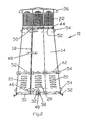
- Figure 1 illustrates a plan view of a cap apparatus or device 10.
- the cap device is installed over a flue opening of a chimney 12, a portion of which is shown in Figure 1 .
- the device 10 would sit at the top of the chimney 12 and surround a flue opening (not visible).
- the device may be mounted on chimneys of various materials and configurations.
- the device 10 includes a plurality of planar sidewalls which are fabricated from flat sheet metal.
- the sidewalls form an octagon and are truncated so to narrow moving away from the chimney toward the top. It will be understood that the device may have a cross-section in the form of a hexagon, square or other configuration within the spirit and scope of the present invention, as defined in the appended claims.
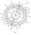
- FIG 2 illustrates a sectional view of the device 10 taken along section line 2-2 of Figure 1 apart from the chimney.
- the sidewalls 14 may be fabricated from two flat metal sheets, each flat metal sheet comprised of four panels each. The two sheets are then brought together and joined at seams 18.
- Each sidewall panel may include a plurality of louver openings 20 which are stamped, punched, formed or otherwise made into the sidewalls 14. Each louver opening 20 faces upward away from the chimney in the direction of the exiting smoke.
- each sidewall panel opposed to the louver openings are a plurality of exit openings 22 in the sidewalls.
- the exit openings 22 are stamped, punched, formed or otherwise made into the sidewalls.
- Each exit opening 22 is relatively small and would not allow for birds, squirrels, or other small animals to crawl therethrough.
- the exit openings 22 are provided so that the total area of the exit openings is at least equal to the cross sectional area of the flue opening and, in a preferred embodiment, is greater than the cross sectional area of the flue opening.
- a top 26 is attached to the upper end of the sidewalls.
- the top 26 may also be fabricated from flat sheet metal. In the embodiment shown, the outer edge of the top is slit and the top is then rolled or pressed.
- the sidewalls 14 and the top 26 are fabricated from copper metal which is decorative and lightweight but relatively soft.
- the device 10 also includes an inner frame and mounting assembly 30.
- the assembly 30 includes a mechanism to both anchor the device 10 to the chimney and to level the device with respect to the chimney.
- the assembly 30 includes a series of L-brackets fabricated from metal which is non-reactive and compatible with the sidewall flat sheet metal.
- the sidewalls are copper and the inner frame mounting assembly is constructed of stainless steel.
- the mounting assembly also includes a plurality of clips 32.
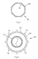
- Figure 3 illustrates a bottom view of the device taken along section line 3-3 of Figure 1 .
- Each clip 32 is receivable in a receptacle 34 in the L-brackets.
- One side of the clip includes an opening 36 for receiving a fastener which will be connected to the chimney 12.
- each clip 32 also includes an elongated slot 38 which receives a fastener 40, such as a bolt, which will pass through the slot 38 and through an opening in the sidewall 14 of the device. Accordingly, by adjusting the positioning of the fastener 40 in the slot 38, the clip 32 may be used to adjust the level of the device with respect to the chimney 12.
- a fastener 40 such as a bolt
- the device 10 also includes a pair of parallel, internal brace rings 42 and 44.
- the brace rings are parallel to the L-brackets of the inner frame 30.
- the continuous internal brace rings 42 and 44 may also be fabricated from L-shaped stainless steel or other metal which is compatible and non-reactive to the sidewalls and be attached by fasteners such as screws or rivets 52 to the sidewalls 14.
- corner braces 46, 48 and 50 are joined together by internal corner braces 46, 48 and 50.
- the corner braces 46, 48 and 50 may be held to the sidewalls by tabs and slots.
- semi-cylindrical molding 54 may be fastened to the sidewalls 14 both as a decorative feature and to hide the fasteners for the internal brace rings as best seen in Figure 2 .
- the edges of the molding terminates in extending tabs which are receivable in slots punched in to the sidewalls. Once inserted, the tabs are twisted to lock in place.
- the entire device may be fabricated without welding, which eliminates undesirable weld marks and which is easy to manufacture.
- a tubular housing is manufactured.
- a pair of flat metal plates are fabricated by punching and folding so that each sheet forms four panels.
- the two sheets are then brought together and joined at the seams 8 so that a truncated octagon is formed.
- the louver openings 20 and the exit openings 22 are stamped into the sidewalls.
- a top 26 is fabricated from flat sheet metal by stamping and folding or rolling.
- the top is connected to the sidewalls by fasteners such as rivets.
- the inner frame and mounting assembly 30 is attached to the sidewalls 14 by rivets. Additionally, the pair of continuous internal inner brace rings 42 and 44 are attached to the sidewalls by rivets.
- the tabs on the moldings 54 are inserted into slots in the sidewalls and the tabs on the moldings 54 are twisted in order to lock the moldings in place.
- the assembled device 10 is lightweight and may be moved to a rooftop for attachment to the chimney 12 using the clips 32 which are received in receptacles in the inner frame and mounting assembly.
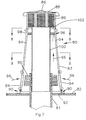
- Figure 4 shows a cross-sectional view of a preferred embodiment of the cap device 60 constructed in accordance with the present invention.
- the device 60 would be installed over a flue opening 61 of a chimney 62, a portion of which is shown in Figure 4 .
- the flue opening 61 extends above the level of the chimney 62 and releases heat and smoke.
- the cap device 60 would sit at the top of the chimney 62 and surround a flue opening 61.
- the cap device 60 includes a tubular housing 64 having a plurality of planar sidewalls which are fabricated from sheet metal.
- the sidewalls form an octagon and are truncated so as to narrow moving away from the chimney 62 toward the top.
- the device 60 may have a tubular housing in the form of a conical cylinder (not shown). Further, it will be understood that the device may have a cross-section in the form of a hexagon, square or other configuration within the spirit and scope of the present invention, as defined in the appended claims.
- Figure 5 is a sectional view o the device 60 taken along section line 5-5 of Figure 4 while Figure 6 is a sectional view taken along section line 6-6 of Figure 4 .
- the tubular housing 64 includes a plurality of louver openings 66 which are stamped, formed, or otherwise made into a lower portion of the tubular housing.
- the louver openings 66 permit atmospheric air to pass through the tubular housing.
- each sidewall panel opposed to the louver openings 66 are a plurality of exit openings 68 which are stamped, punched, formed, or otherwise made into the sidewalls.
- Each exit opening 68 is relatively small and will not allow for birds, squirrels or other small animals to crawl therethrough.
- the exit openings are at least equal to a cross-sectional area of the flue opening 61.
- the tubular housing 64 thus, has an imperforated portion between the lower and the upper portion.
- a top 70 is attached to the upper end of the tubular housing 64 by fasteners.
- the top may be fabricated from flat sheet metal with the outer edge of the top being split and then rolled or pressed to form a downward lip.
- a heat shield liner 71 is installed beneath the top 70 so that the top 70 is insulated from heat.
- the cap device 60 also includes an inner frame and mounting assembly 72 as previously described in detail above with respect to the embodiment in Figures 1 through 3 .
- the assembly 72 includes a series of L-brackets 74.
- the cap device 60 also includes a liner 76 which extends from the lower area of the louver openings 66 past the imperforated section and up to the exit openings 68.
- the liner 76 is cylindrical (circular in cross section) while the tubular housing 64 is in a polygon form so that spaces exist between the liner 76 and the tubular housing. Accordingly, as seen in Figure 4 , ambient air is drawn through the louvers 66 as illustrated by arrows 78, up through the spaces between the liner 76 and the tubular housing 64 and out of the exit openings as shown by arrows 79.
- ambient air enters the chambers or spaces between the tubular housing 64 and the liner 76.
- the liner 76 will be heated from rising heat and smoke from the flue 61. Accordingly, the warm air will be encouraged and drawn upward through the spaces where it will mix with smoke rising from the flue 61 and thereafter be drawn out to the atmosphere through the exit openings 68 as shown by arrows 79. Accordingly, the ambient air moving in the spaces or chambers between the liner and the tubular housing not only acts to insulate the tubular housing 64 from heat but also acts to assist in drawing smoke from the flue upward and out of the exit openings 68.
- Figure 7 shows a cross-sectional view of a second, alternate embodiment of the cap device 80 constructed in accordance with the present invention.
- the cap device 80 would be installed over a metal flue pipe opening 81 of a chimney 82, a portion of which is shown in Figure 7 .
- the flue opening 81 extends above the level of the chimney 82.
- the cap device would sit at the top of the chimney 82 and surround the flue opening 81.
- the device 80 includes a tubular housing having 83 a plurality of planar sidewalls fabricated from sheet metal.
- the sidewalls form an octagon and are truncated so as to narrow moving away from the chimney toward the top.
- the device 80 may have a tubular housing in the form of a conical cylinder (not shown). Further, it will be understood that the device 80 may have other configurations.
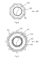
- Figure 8 is a sectional view taken along section line 8-8 of Figure 7 while Figure 9 is a sectional view taken along section line 9-9 of Figure 7 .
- the tubular housing 83 includes a plurality of louver openings 84 which are stamped, formed or otherwise made into a lower portion of the tubular housing.
- each exit opening 86 is relatively small and will not allow for birds, squirrels or other small animals to crawl therethrough.
- the exit openings are at least equal to a cross-sectional area of the metal flue pipe opening 81.
- the tubular housing 83 thus, has an imperforated portion between the lower, louver openings and the upper, exit openings.
- a top 88 is attached to the upper end of the tubular housing 83 by fasteners.
- the top may be fabricated from flat sheet metal with the outer edge of the top being split and then rolled or pressed to form a downward lip.
- a heat shield liner 89 is installed beneath the top 88 so that the top 88 is insulated heat.
- the cap device 80 includes an inner frame and mounting assembly 90 as previously described in detail above with respect to the other embodiments.
- the inner frame and mounting assembly 90 includes a series of L-brackets 92.
- the cap device 80 also includes a liner 94 which extends generally from the lower area of the louver openings 84 upward through the imperforated portion and up toward the exit openings 86. As best seen in Figure 9 , the liner 94 is conical (circular in cross-section) while the tubular housing 83 is in a polygon form.
- the liner 94 contains an opening or openings 95 adjacent the louver openings 84 so that ambient air is drawn through the louver openings and through the liner 94 into the tubular housing as illustrated by arrows 96 outside the housing and arrows 96 within the housing.
- a set of upper louver openings 86 allow air to pass back out into the atmosphere as shown by arrows 96.
- the cap device 80 also includes an inner sleeve 100 which it is to fit within the metal flue pipe opening 81. Accordingly, smoke is drawn upward through the flue opening where it exits through the exit openings 86 to the atmosphere. As seen in Figures 7 and 8 , a plate 102 extends radially from the tubular housing to the sleeve 100 to form a barrier. The space between the sleeve 100 and the liner in tubular housing 94 forms a space to insulate the tubular housing 83 from the heat rising from the flue 81 and through the sleeve 100.
Landscapes
- Engineering & Computer Science (AREA)
- Chemical & Material Sciences (AREA)
- Combustion & Propulsion (AREA)
- Mechanical Engineering (AREA)
- General Engineering & Computer Science (AREA)
- Architecture (AREA)
- Civil Engineering (AREA)
- Structural Engineering (AREA)
- Ventilation (AREA)
- Air-Flow Control Members (AREA)
- Catching Or Destruction (AREA)
Claims (12)
- Aufsatz (60, 80)a) für eine Rauchaustrittsöffnung eines Schornsteins (62, 82) zur Verbesserung des Rauchabzugs und zum Schutz gegen das Eindringen von Tieren, Fremdkörpern und Naturgewalten,b) wobei der Aufsatz Folgendes aufweist:c) ein rohrförmiges Gehäuse (64, 83) mit mehreren ebenen Seitenwänden, die aus ebenen Blechen hergestellt sind,d) ein Deckel (70, 88), die an dem rohrförmigen Gehäuse (64, 83) angebracht ist,
gekennzeichnet durche) mehrere Lüftungsöffnungen (66, 84) in einem unteren Bereich des rohrförmigen Gehäuses, um Luft anzusaugen,f) mehrere Austrittsöffnungen (68, 86) in dem oberen Bereich des rohrförmigen Gehäuses über den Lüftungsöffnungen (66, 84), wobei das rohrförmige Gehäuse (64, 83) einen unperforierten Bereich zwischen dem unteren und dem oberen Bereich aufweist,g) eine innere Rahmen- und Befestigungsanordnung (72, 90), die an dem unteren Rand jeder Seitenwand angebracht ist und die eine Verankerungs- und Ausrichteinrichtung (74, 92) umfasst, um die innere Rahmen- und Befestigungsanordnung (72, 90) an dem Schornstein (62, 82) zu verankern und die Vorrichtung bezüglich des Schornsteins auszurichten, undh) eine Auskleidung (76, 94) in dem rohrförmigen Gehäuse (64, 83), um wenigstens einen Raum zwischen der Auskleidung und dem rohrförmigen Gehäuse zu bilden, so dass Luft durch die Lüftungsöffnungen nach oben durch den Raum und aus den Austrittsöffnungen gesaugt wird. - Aufsatz nach Anspruch 1, wobei die innere Rahmen- und Befestigungsanordnung (72, 90) aus L-Laschen aus Metall hergestellt ist.
- Aufsatz nach Anspruch 2, wobei die Seitenwände und der Deckel (70, 88) aus Kupfer bestehen und die innere Rahmen- und Befestigungsanordnung (72, 90) aus rostfreiem Stahl besteht.
- Aufsatz nach Anspruch 1, wobei die innere Rahmen- und Befestigungsanordnung (72, 90) Aufnahmen (34) umfasst, und wobei die Verankerungs- und Ausrichteinrichtung mehrere Clips (32) umfasst, die an dem Schornstein befestigbar sind, und wobei die Clips in den Aufnahmen in der inneren Rahmen- und Befestigungsanordnung des Aufsatzes aufgenommen werden können.
- Aufsatz nach Anspruch 4, wobei jeder Clip (32) einen Längsschlitz (38) aufweist, um die Höhe des Aufsatzes zu verstellen.
- Aufsatz nach Anspruch 1, umfassend mehrere durchgehende Ringstreben (42, 44), die entlang der Innenfläche des Gehäuses beabstandet sind.
- Aufsatz nach Anspruch 6, umfassend ein Paar Ringstreben (42, 44), die parallel zueinander liegen.
- Aufsatz nach Anspruch 1, wobei das rohrförmige Gehäuse (64, 83) einzelne Paneele umfasst, die durch innere Eckklammern verbunden sind.
- Aufsatz nach Anspruch 1, wobei das rohrförmige Gehäuse (64, 83) eine Querschnittsform hat, die aus einer Gruppe bestehend aus einem achteckigen, sechseckigen, quadratischen, rechteckigen und einem kreisförmigen Querschnitt ausgewählt ist.
- Aufsatz nach Anspruch 1, wobei der Deckel (70, 88) aus dem Flachblech hergestellt ist.
- Aufsatz nach Anspruch 1, wobei die Lüftungsöffnungen (66, 84) und die Austrittsöffnungen (68, 86) in das ebene Blech eingestanzt sind.
- Aufsatz nach Anspruch 1, wobei jede der Lüftungsöffnungen (66, 84) nach oben weist, um den Luftzug zu verbessern.
Applications Claiming Priority (2)
| Application Number | Priority Date | Filing Date | Title |
|---|---|---|---|
| US11/160,160 US7179164B2 (en) | 2004-05-17 | 2005-06-10 | Chimney cap apparatus and method |
| PCT/US2006/018169 WO2006135517A1 (en) | 2005-06-10 | 2006-05-11 | Chimney cap apparatus and method |
Publications (2)
| Publication Number | Publication Date |
|---|---|
| EP1904698A1 EP1904698A1 (de) | 2008-04-02 |
| EP1904698B1 true EP1904698B1 (de) | 2011-07-27 |
Family
ID=36940478
Family Applications (1)
| Application Number | Title | Priority Date | Filing Date |
|---|---|---|---|
| EP06759530A Not-in-force EP1904698B1 (de) | 2005-06-10 | 2006-05-11 | Aufsatzvorrichtung für einen schornstein |
Country Status (6)
| Country | Link |
|---|---|
| US (1) | US7179164B2 (de) |
| EP (1) | EP1904698B1 (de) |
| AT (1) | ATE518038T1 (de) |
| CA (1) | CA2603924C (de) |
| DK (1) | DK1904698T3 (de) |
| WO (1) | WO2006135517A1 (de) |
Cited By (1)
| Publication number | Priority date | Publication date | Assignee | Title |
|---|---|---|---|---|
| USD1023282S1 (en) | 2020-07-31 | 2024-04-16 | Ipex Technologies Inc. | Rain cap for gas venting system |
Families Citing this family (20)
| Publication number | Priority date | Publication date | Assignee | Title |
|---|---|---|---|---|
| US20090017741A1 (en) * | 2007-07-13 | 2009-01-15 | John G. Arnold, Jr. | Chimney cap with replaceable or recyclable ceramic catalytic filter insert |
| CN101126507B (zh) * | 2007-08-27 | 2010-06-30 | 白玉明 | 一种烟囱防风装置 |
| US8083574B2 (en) * | 2007-09-27 | 2011-12-27 | John G. Arnold, Jr. | Exhaust flue cap and filter device for a gas fired appliance |
| US9863634B1 (en) | 2007-09-27 | 2018-01-09 | European Copper, Llc | Exhaust flue cap and filter device for a gas fired appliance |
| NZ569850A (en) * | 2008-07-16 | 2011-03-31 | Herville Neville Donald D | Chimney cover with diffuser and sleeve sides enclosing expansion area |
| US8696416B1 (en) * | 2009-08-21 | 2014-04-15 | European Copper, Llc | Multi-Purpose chimney cap device |
| USD677375S1 (en) | 2011-09-20 | 2013-03-05 | European Copper, Llc | Direct vent exhaust termination |
| USD677374S1 (en) | 2011-09-20 | 2013-03-05 | European Copper, Llc | B vent exhaust termination |
| US9392905B2 (en) * | 2012-02-23 | 2016-07-19 | Smokeware.Net Llc | Vented chimney cap assembly |
| US9615693B1 (en) * | 2012-02-23 | 2017-04-11 | Smokeware.Net Llc | Vented chimney cap system and method thereof |
| DE102013111958A1 (de) * | 2013-10-30 | 2015-04-30 | emtec-systeme GmbH+Co. KG | Vorrichtung zur Abdeckung von Kaminen oder Schornsteinen |
| CN104315300B (zh) * | 2014-09-25 | 2016-04-06 | 广州威能机电有限公司 | 排气管及其端部防雨装置 |
| US10077635B2 (en) * | 2015-05-15 | 2018-09-18 | Baker Hughes, A Ge Company, Llc | Debris catcher |
| USD802730S1 (en) * | 2016-03-24 | 2017-11-14 | John G. Arnold, Jr. | Chimney pot |
| USD802731S1 (en) * | 2016-03-24 | 2017-11-14 | John G. Arnold, Jr. | Chimney pot |
| USD802729S1 (en) * | 2016-03-24 | 2017-11-14 | John G. Arnold, Jr. | Chimney pot |
| IT201600070345A1 (it) * | 2016-07-06 | 2018-01-06 | Anouk Immobiliare S R L | “terminale per comignolo ad efficienza migliorata e costituente struttura di supporto per una struttura di comignolo prefabbricato” |
| JP6384766B2 (ja) * | 2016-09-23 | 2018-09-05 | 小林 久男 | 煙突覆い装置 |
| CA177717S (en) * | 2017-04-27 | 2018-10-22 | Sk Tuote Oy | Exhaust vent |
| PL71079Y1 (pl) * | 2018-05-24 | 2019-11-29 | Krono Plast Januszka Tadeusiak Spolka Jawna | Daszek kominka wentylacyjnego |
Family Cites Families (18)
| Publication number | Priority date | Publication date | Assignee | Title |
|---|---|---|---|---|
| US638172A (en) * | 1899-02-04 | 1899-11-28 | Charles Edwin Burress | Chimney-top. |
| US847255A (en) * | 1906-08-27 | 1907-03-12 | Fredrich J Kobusch | Ventilator. |
| US1644701A (en) * | 1925-06-06 | 1927-10-11 | Alfred B Anderson | Ventilator and the like |
| US1627105A (en) * | 1925-06-16 | 1927-05-03 | William J Meier | Chimney |
| US2381178A (en) * | 1944-07-27 | 1945-08-07 | Lester H Munyon | Chimney liner extension |
| US2763196A (en) * | 1953-05-04 | 1956-09-18 | Woodlin Metal Products | Universal roof stack |
| US2856837A (en) * | 1955-06-10 | 1958-10-21 | Robert K Thulman | Chimney top |
| US3103158A (en) * | 1960-06-01 | 1963-09-10 | Frank P Noll | Ventilating device |
| US3269296A (en) * | 1964-05-19 | 1966-08-30 | Charles A Best | Ventilating device |
| US3817162A (en) * | 1973-03-27 | 1974-06-18 | Research Corp | Flue stack outlet |
| US4286975A (en) * | 1979-10-02 | 1981-09-01 | Whiteley Isaac C | Chimney heat exchanger |
| USD299529S (en) * | 1986-10-16 | 1989-01-24 | Best James J | Draft intensifier for a fireplace chimney |
| US4732078A (en) * | 1987-04-24 | 1988-03-22 | Frank Giumenta | Chimney cap |
| DE8807961U1 (de) * | 1988-06-21 | 1988-08-11 | Paril, Hugo, 8070 Ingolstadt | Kaminaufsatz |
| US5125198A (en) * | 1991-03-18 | 1992-06-30 | Fredric Giumenta | Dual fitting chimney cap |
| US5402613A (en) * | 1993-12-07 | 1995-04-04 | Giumenta; Frederic F. | Chimney cap |
| US6152817A (en) * | 1998-06-23 | 2000-11-28 | Gelco Manufacturing, Inc. | Chimney cover |
| US6926600B1 (en) | 2004-05-17 | 2005-08-09 | European Copper, Llc | Chimney cap apparatus and method |
-
2005
- 2005-06-10 US US11/160,160 patent/US7179164B2/en not_active Expired - Lifetime
-
2006
- 2006-05-11 WO PCT/US2006/018169 patent/WO2006135517A1/en not_active Ceased
- 2006-05-11 EP EP06759530A patent/EP1904698B1/de not_active Not-in-force
- 2006-05-11 DK DK06759530.6T patent/DK1904698T3/da active
- 2006-05-11 AT AT06759530T patent/ATE518038T1/de not_active IP Right Cessation
- 2006-05-11 CA CA2603924A patent/CA2603924C/en active Active
Cited By (1)
| Publication number | Priority date | Publication date | Assignee | Title |
|---|---|---|---|---|
| USD1023282S1 (en) | 2020-07-31 | 2024-04-16 | Ipex Technologies Inc. | Rain cap for gas venting system |
Also Published As
| Publication number | Publication date |
|---|---|
| CA2603924C (en) | 2014-03-25 |
| CA2603924A1 (en) | 2006-12-21 |
| US20060246833A1 (en) | 2006-11-02 |
| EP1904698A1 (de) | 2008-04-02 |
| DK1904698T3 (da) | 2011-11-14 |
| US7179164B2 (en) | 2007-02-20 |
| ATE518038T1 (de) | 2011-08-15 |
| WO2006135517A1 (en) | 2006-12-21 |
Similar Documents
| Publication | Publication Date | Title |
|---|---|---|
| EP1904698B1 (de) | Aufsatzvorrichtung für einen schornstein | |
| US6926600B1 (en) | Chimney cap apparatus and method | |
| US7044852B2 (en) | Off-ridge roof vent | |
| US6128870A (en) | Roof vent system | |
| US5924925A (en) | Roof ventilating system for frame construction building | |
| US6931792B2 (en) | Universal end cap and method for rain gutter debris guards | |
| CA1068866A (en) | Rafter vent | |
| US20080299892A1 (en) | S-shaped roof vent, ventilated roof employing the same and method of installing the same | |
| EP1915488B1 (de) | Hybrid-metall-kunststoff-dachentlüftung | |
| HUT73600A (en) | Roof ventilation device | |
| US8544216B1 (en) | Portable corrugated plastic shelter | |
| US9016008B2 (en) | Roofing cap system | |
| US20060223437A1 (en) | Low profile roof vent | |
| US6954947B1 (en) | Pluming vent cover | |
| US6240690B1 (en) | Vented metal roof | |
| US20160312474A1 (en) | Roofing cap system | |
| US5897434A (en) | Chimney cap hood | |
| DE69922597T2 (de) | Dachlüfter | |
| US20250320726A1 (en) | Vented fascia trim piece | |
| US7216466B2 (en) | Universal ridge clip | |
| KR200297857Y1 (ko) | 판넬 지붕의 후레싱 | |
| JP3783145B2 (ja) | 屋上設置型換気装置 | |
| JP2009203700A (ja) | 棟換気塔 | |
| AU2021200672A1 (en) | Fascia Panel | |
| JP3356998B2 (ja) | 通気口用ガラリ |
Legal Events
| Date | Code | Title | Description |
|---|---|---|---|
| PUAI | Public reference made under article 153(3) epc to a published international application that has entered the european phase |
Free format text: ORIGINAL CODE: 0009012 |
|
| 17P | Request for examination filed |
Effective date: 20071210 |
|
| AK | Designated contracting states |
Kind code of ref document: A1 Designated state(s): AT BE BG CH CY CZ DE DK EE ES FI FR GB GR HU IE IS IT LI LT LU LV MC NL PL PT RO SE SI SK TR |
|
| DAX | Request for extension of the european patent (deleted) | ||
| 17Q | First examination report despatched |
Effective date: 20091008 |
|
| GRAP | Despatch of communication of intention to grant a patent |
Free format text: ORIGINAL CODE: EPIDOSNIGR1 |
|
| RTI1 | Title (correction) |
Free format text: CAP DEVICE FOR A CHIMNEY |
|
| RTI1 | Title (correction) |
Free format text: CAP DEVICE FOR A CHIMNEY |
|
| GRAS | Grant fee paid |
Free format text: ORIGINAL CODE: EPIDOSNIGR3 |
|
| GRAA | (expected) grant |
Free format text: ORIGINAL CODE: 0009210 |
|
| AK | Designated contracting states |
Kind code of ref document: B1 Designated state(s): AT BE BG CH CY CZ DE DK EE ES FI FR GB GR HU IE IS IT LI LT LU LV MC NL PL PT RO SE SI SK TR |
|
| REG | Reference to a national code |
Ref country code: GB Ref legal event code: FG4D |
|
| REG | Reference to a national code |
Ref country code: CH Ref legal event code: EP |
|
| REG | Reference to a national code |
Ref country code: DE Ref legal event code: R096 Ref document number: 602006023356 Country of ref document: DE Effective date: 20110915 |
|
| REG | Reference to a national code |
Ref country code: NL Ref legal event code: T3 |
|
| REG | Reference to a national code |
Ref country code: SE Ref legal event code: TRGR |
|
| REG | Reference to a national code |
Ref country code: DK Ref legal event code: T3 |
|
| REG | Reference to a national code |
Ref country code: AT Ref legal event code: MK05 Ref document number: 518038 Country of ref document: AT Kind code of ref document: T Effective date: 20110727 |
|
| PG25 | Lapsed in a contracting state [announced via postgrant information from national office to epo] |
Ref country code: FI Free format text: LAPSE BECAUSE OF FAILURE TO SUBMIT A TRANSLATION OF THE DESCRIPTION OR TO PAY THE FEE WITHIN THE PRESCRIBED TIME-LIMIT Effective date: 20110727 Ref country code: LT Free format text: LAPSE BECAUSE OF FAILURE TO SUBMIT A TRANSLATION OF THE DESCRIPTION OR TO PAY THE FEE WITHIN THE PRESCRIBED TIME-LIMIT Effective date: 20110727 Ref country code: IS Free format text: LAPSE BECAUSE OF FAILURE TO SUBMIT A TRANSLATION OF THE DESCRIPTION OR TO PAY THE FEE WITHIN THE PRESCRIBED TIME-LIMIT Effective date: 20111127 Ref country code: BE Free format text: LAPSE BECAUSE OF FAILURE TO SUBMIT A TRANSLATION OF THE DESCRIPTION OR TO PAY THE FEE WITHIN THE PRESCRIBED TIME-LIMIT Effective date: 20110727 Ref country code: PT Free format text: LAPSE BECAUSE OF FAILURE TO SUBMIT A TRANSLATION OF THE DESCRIPTION OR TO PAY THE FEE WITHIN THE PRESCRIBED TIME-LIMIT Effective date: 20111128 |
|
| PG25 | Lapsed in a contracting state [announced via postgrant information from national office to epo] |
Ref country code: SI Free format text: LAPSE BECAUSE OF FAILURE TO SUBMIT A TRANSLATION OF THE DESCRIPTION OR TO PAY THE FEE WITHIN THE PRESCRIBED TIME-LIMIT Effective date: 20110727 Ref country code: AT Free format text: LAPSE BECAUSE OF FAILURE TO SUBMIT A TRANSLATION OF THE DESCRIPTION OR TO PAY THE FEE WITHIN THE PRESCRIBED TIME-LIMIT Effective date: 20110727 Ref country code: LV Free format text: LAPSE BECAUSE OF FAILURE TO SUBMIT A TRANSLATION OF THE DESCRIPTION OR TO PAY THE FEE WITHIN THE PRESCRIBED TIME-LIMIT Effective date: 20110727 Ref country code: GR Free format text: LAPSE BECAUSE OF FAILURE TO SUBMIT A TRANSLATION OF THE DESCRIPTION OR TO PAY THE FEE WITHIN THE PRESCRIBED TIME-LIMIT Effective date: 20111028 Ref country code: PL Free format text: LAPSE BECAUSE OF FAILURE TO SUBMIT A TRANSLATION OF THE DESCRIPTION OR TO PAY THE FEE WITHIN THE PRESCRIBED TIME-LIMIT Effective date: 20110727 Ref country code: CY Free format text: LAPSE BECAUSE OF FAILURE TO SUBMIT A TRANSLATION OF THE DESCRIPTION OR TO PAY THE FEE WITHIN THE PRESCRIBED TIME-LIMIT Effective date: 20110727 |
|
| PG25 | Lapsed in a contracting state [announced via postgrant information from national office to epo] |
Ref country code: CZ Free format text: LAPSE BECAUSE OF FAILURE TO SUBMIT A TRANSLATION OF THE DESCRIPTION OR TO PAY THE FEE WITHIN THE PRESCRIBED TIME-LIMIT Effective date: 20110727 Ref country code: SK Free format text: LAPSE BECAUSE OF FAILURE TO SUBMIT A TRANSLATION OF THE DESCRIPTION OR TO PAY THE FEE WITHIN THE PRESCRIBED TIME-LIMIT Effective date: 20110727 |
|
| PG25 | Lapsed in a contracting state [announced via postgrant information from national office to epo] |
Ref country code: RO Free format text: LAPSE BECAUSE OF FAILURE TO SUBMIT A TRANSLATION OF THE DESCRIPTION OR TO PAY THE FEE WITHIN THE PRESCRIBED TIME-LIMIT Effective date: 20110727 Ref country code: EE Free format text: LAPSE BECAUSE OF FAILURE TO SUBMIT A TRANSLATION OF THE DESCRIPTION OR TO PAY THE FEE WITHIN THE PRESCRIBED TIME-LIMIT Effective date: 20110727 Ref country code: IT Free format text: LAPSE BECAUSE OF FAILURE TO SUBMIT A TRANSLATION OF THE DESCRIPTION OR TO PAY THE FEE WITHIN THE PRESCRIBED TIME-LIMIT Effective date: 20110727 |
|
| PLBE | No opposition filed within time limit |
Free format text: ORIGINAL CODE: 0009261 |
|
| STAA | Information on the status of an ep patent application or granted ep patent |
Free format text: STATUS: NO OPPOSITION FILED WITHIN TIME LIMIT |
|
| 26N | No opposition filed |
Effective date: 20120502 |
|
| PGFP | Annual fee paid to national office [announced via postgrant information from national office to epo] |
Ref country code: NL Payment date: 20120605 Year of fee payment: 7 Ref country code: DK Payment date: 20120531 Year of fee payment: 7 Ref country code: MC Payment date: 20120525 Year of fee payment: 7 Ref country code: DE Payment date: 20120530 Year of fee payment: 7 Ref country code: CH Payment date: 20120522 Year of fee payment: 7 Ref country code: IE Payment date: 20120524 Year of fee payment: 7 Ref country code: LU Payment date: 20120531 Year of fee payment: 7 |
|
| REG | Reference to a national code |
Ref country code: DE Ref legal event code: R097 Ref document number: 602006023356 Country of ref document: DE Effective date: 20120502 |
|
| PGFP | Annual fee paid to national office [announced via postgrant information from national office to epo] |
Ref country code: GB Payment date: 20120522 Year of fee payment: 7 Ref country code: SE Payment date: 20120525 Year of fee payment: 7 Ref country code: FR Payment date: 20120618 Year of fee payment: 7 |
|
| PG25 | Lapsed in a contracting state [announced via postgrant information from national office to epo] |
Ref country code: BG Free format text: LAPSE BECAUSE OF FAILURE TO SUBMIT A TRANSLATION OF THE DESCRIPTION OR TO PAY THE FEE WITHIN THE PRESCRIBED TIME-LIMIT Effective date: 20111027 |
|
| PG25 | Lapsed in a contracting state [announced via postgrant information from national office to epo] |
Ref country code: ES Free format text: LAPSE BECAUSE OF FAILURE TO SUBMIT A TRANSLATION OF THE DESCRIPTION OR TO PAY THE FEE WITHIN THE PRESCRIBED TIME-LIMIT Effective date: 20111107 |
|
| REG | Reference to a national code |
Ref country code: NL Ref legal event code: V1 Effective date: 20131201 |
|
| PG25 | Lapsed in a contracting state [announced via postgrant information from national office to epo] |
Ref country code: MC Free format text: LAPSE BECAUSE OF NON-PAYMENT OF DUE FEES Effective date: 20130531 |
|
| REG | Reference to a national code |
Ref country code: CH Ref legal event code: PL |
|
| REG | Reference to a national code |
Ref country code: SE Ref legal event code: EUG |
|
| GBPC | Gb: european patent ceased through non-payment of renewal fee |
Effective date: 20130511 |
|
| PG25 | Lapsed in a contracting state [announced via postgrant information from national office to epo] |
Ref country code: DE Free format text: LAPSE BECAUSE OF NON-PAYMENT OF DUE FEES Effective date: 20131203 Ref country code: CH Free format text: LAPSE BECAUSE OF NON-PAYMENT OF DUE FEES Effective date: 20130531 Ref country code: LI Free format text: LAPSE BECAUSE OF NON-PAYMENT OF DUE FEES Effective date: 20130531 Ref country code: SE Free format text: LAPSE BECAUSE OF NON-PAYMENT OF DUE FEES Effective date: 20130512 |
|
| REG | Reference to a national code |
Ref country code: DK Ref legal event code: EBP Effective date: 20130531 |
|
| REG | Reference to a national code |
Ref country code: IE Ref legal event code: MM4A |
|
| REG | Reference to a national code |
Ref country code: DE Ref legal event code: R119 Ref document number: 602006023356 Country of ref document: DE Effective date: 20131203 |
|
| PG25 | Lapsed in a contracting state [announced via postgrant information from national office to epo] |
Ref country code: NL Free format text: LAPSE BECAUSE OF NON-PAYMENT OF DUE FEES Effective date: 20131201 |
|
| REG | Reference to a national code |
Ref country code: FR Ref legal event code: ST Effective date: 20140131 |
|
| PG25 | Lapsed in a contracting state [announced via postgrant information from national office to epo] |
Ref country code: TR Free format text: LAPSE BECAUSE OF FAILURE TO SUBMIT A TRANSLATION OF THE DESCRIPTION OR TO PAY THE FEE WITHIN THE PRESCRIBED TIME-LIMIT Effective date: 20110727 Ref country code: IE Free format text: LAPSE BECAUSE OF NON-PAYMENT OF DUE FEES Effective date: 20130511 Ref country code: GB Free format text: LAPSE BECAUSE OF NON-PAYMENT OF DUE FEES Effective date: 20130511 Ref country code: DK Free format text: LAPSE BECAUSE OF NON-PAYMENT OF DUE FEES Effective date: 20130531 |
|
| PG25 | Lapsed in a contracting state [announced via postgrant information from national office to epo] |
Ref country code: FR Free format text: LAPSE BECAUSE OF NON-PAYMENT OF DUE FEES Effective date: 20130531 |
|
| PG25 | Lapsed in a contracting state [announced via postgrant information from national office to epo] |
Ref country code: HU Free format text: LAPSE BECAUSE OF FAILURE TO SUBMIT A TRANSLATION OF THE DESCRIPTION OR TO PAY THE FEE WITHIN THE PRESCRIBED TIME-LIMIT Effective date: 20060511 |
|
| PG25 | Lapsed in a contracting state [announced via postgrant information from national office to epo] |
Ref country code: LU Free format text: LAPSE BECAUSE OF NON-PAYMENT OF DUE FEES Effective date: 20130511 |