EP1903587B1 - Fernbedienung - Google Patents
Fernbedienung Download PDFInfo
- Publication number
- EP1903587B1 EP1903587B1 EP07018388A EP07018388A EP1903587B1 EP 1903587 B1 EP1903587 B1 EP 1903587B1 EP 07018388 A EP07018388 A EP 07018388A EP 07018388 A EP07018388 A EP 07018388A EP 1903587 B1 EP1903587 B1 EP 1903587B1
- Authority
- EP
- European Patent Office
- Prior art keywords
- remote controller
- operational
- button
- top case
- operational button
- Prior art date
- Legal status (The legal status is an assumption and is not a legal conclusion. Google has not performed a legal analysis and makes no representation as to the accuracy of the status listed.)
- Expired - Fee Related
Links
Images


Classifications
-
- H—ELECTRICITY
- H01—ELECTRIC ELEMENTS
- H01H—ELECTRIC SWITCHES; RELAYS; SELECTORS; EMERGENCY PROTECTIVE DEVICES
- H01H9/00—Details of switching devices, not covered by groups H01H1/00 - H01H7/00
- H01H9/02—Bases, casings, or covers
- H01H9/0214—Hand-held casings
- H01H9/0235—Hand-held casings specially adapted for remote control, e.g. of audio or video apparatus
-
- H—ELECTRICITY
- H01—ELECTRIC ELEMENTS
- H01H—ELECTRIC SWITCHES; RELAYS; SELECTORS; EMERGENCY PROTECTIVE DEVICES
- H01H2221/00—Actuators
- H01H2221/058—Actuators to avoid tilting or skewing of contact area or actuator
-
- H—ELECTRICITY
- H01—ELECTRIC ELEMENTS
- H01H—ELECTRIC SWITCHES; RELAYS; SELECTORS; EMERGENCY PROTECTIVE DEVICES
- H01H2221/00—Actuators
- H01H2221/06—Actuators to avoid sticking in on position
Definitions
- the present invention relates to a remote controller for remote control of various types of equipment.
- general electric equipment that can be controlled by a remote controller includes a television set that receives broadcasting programs and displays them, a moving image recording and reproducing device that records moving image information (including sound information) such as a broadcasting program or the like on a recording medium and reads the recording information so that the moving image can be reproduced like an HDD (Hard Disk Drive) recorder, a DVD (Digital Versatile Disk) recorder or a video tape recorder, an audio visual device such as a stereo set that reproduces music and sounds, an air conditioner and the like.
- Control of the electric equipment by using the remote controller is performed when a user presses a desired operational button on the remote controller and then an instruction signal assigned to the operational button is transmitted from the remote controller.
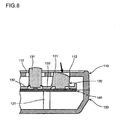
- a conventional ordinary remote controller has a casing made up of a top case 110 and a bottom case 120, in which an operational button body 130, a circuit board 140, a transmitter (not shown), a battery (not shown) and the like are disposed (see JP-A-H5-205559 and JP-A-2006-19880 , for example).
- the circuit board 140 is supported in the state sandwiched between a lower column 121 protruding from the inner surface of the bottom case 120 and an upper column (not shown) protruding from the inner surface of the top case 110.
- the bottom case 120 and the top case 110 are fastened to each other with screws.
- the operational button body 130 is made of an elastic material such as silicone rubber. It has integrally a plurality of operational buttons 131 arranged with a predetermined space and a base portion 132 disposed among the operational buttons 131 and connected to neighboring operational buttons 131. This operational button body 130 is supported in the state where its base portion 132 is put on the circuit board 140 and pushed by a grid-like rib 111 protruding from the inner face of the top case 110 (see Fig. 6 ) onto the circuit board 140.
- the top case 110 is provided with through holes 112 formed at positions corresponding to the operational buttons 131, and the operational buttons 131 are exposed from the through holes 112.
- Each of the operational buttons 131 is floated from the circuit board 140 slightly, and switch contacts are disposed on the circuit board 140 directly below the operational buttons 131.
- buttons 131 Although pressing operation by a light force or a strong force right down is expected naturally as the operation of the operational button 131, some users may press it by a strong force in a slanting direction. In this case, a state of so-called button stuck may occur in the above mentioned conventional remote controller as shown in Fig. 8 , in which the operational button 131 pressed by a strong force in a slanting direction enters lower than the through hole 112 so that a corner of its upper surface enters along the inner surface of the top case 110 locally. Even if the pressing operation is cancelled in this state, the corner of the upper surface of the pressed bottom is caught by the inner surface of the top case 110 so that the pressed state of the bottom remains. If such a button stuck state occurs, not only the stuck operational button 131 but also other operational buttons 131 cannot be operated because the switch contact of the stuck operational button remains in the connected state.
- JP 63 102 491 discloses a remote control unit including an insulating sheet and an insulating base plate which are positioned by means of a boss formed in an upper case and by a rib formed in a lower case.
- the insulating sheet and the insulating base plate are put between the upper and lower cases and fixed, and the unit is fixed by means of a screw. Therefore, only by combining and positioning the upper case and the lower case, accuracy of each part can be lowered and the shape is simplified, accordingly, the assembling speed of the remote control unit can be improved.
- EP 1 560 240 discloses a key switch that includes a front cover formed with a cursor key hole.
- a first rib is formed on a first support wall and a second rib is formed on a second support wall. Accordingly, when a cursor key part disposed in the cursor key hole is pressed, it can be restrained against motion in a shorter side direction. The operability of a cursor key can be improved, which allows a correct operation.
- the present invention is made in view of the above described problem and it is an object of the present invention to provide a remote controller in which pressing operation of its operational button can be performed securely.
- a remote controller includes a top case having a plurality of through holes, a plurality of operational buttons exposed respectively from the through holes of the top case, so that each of the operational buttons is pressed for controlling the equipment, and ribs protruding from the inner surface of the top case, wherein the remote controller is characterized by a structure in which the ribs continue the respective through holes along the circumferences thereof.
- the remote controller according to the present invention may further comprise a grid-like rib protruding from the inner surface of the top case of the remote controller, separate from the circumference of the through holes.
- a body of the operational buttons is supported in the state where its base portion is put onto a circuit board and pushed by the grid-like rib.
- the above-mentioned equipment may be a television set that receives and displays a broadcasting program.
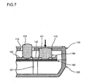
- Fig. 1 is a cross sectional view to show a main portion of a remote controller according to an embodiment of the present invention.
- Fig. 1 is a cross sectional view to show a main portion of an remote controller according to an embodiment of the present invention
- Fig. 2 is a perspective view of a top case of the remote controller viewed from the inside
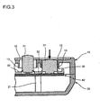
- Figs. 3 and Fig. 4 are cross sectional views to show an example of an operating state of the remote controller.
- Fig. 3 shows the state where an operational button is pressed by a strong force right down
- Fig. 4 shows the state where the operational button is pressed by a strong force in a slanting direction.
- the remote controller of this embodiment is used for controlling a television set as an example of electric equipment.
- the television set has an essential function to receive moving image information (including sound information) of a broadcasting program of each channel and displaying the moving image for a user to watch.
- the remote controller has a casing made up of a top case 10 and a bottom case 20, in which an operational button body 30, a circuit board 40, a transmitter (not shown), a battery (not shown) and the like are disposed.
- the top case 10 and the bottom case 20 of this embodiment are molded of a synthetic resin such as polystylene or acrylonitrile-butadiene copolymer.
- the circuit board 40 is supported in the state sandwiched between a lower column 21 protruding from the inner surface of the bottom case 20 and an upper column (not shown) protruding from the inner surface of the top case 10.
- the bottom case 20 and the top case 10 are fastened to each other with screws.
- the operational button body 30 is made of an elastic material such as silicone rubber. It has integrally a plurality of operational buttons 31 arranged with a predetermined space and a base portion 32 disposed among the operational buttons 31 and connected to neighboring operational buttons 31.
- the operational button 31 has a cylindrical shape or a square pole shape. This operational button body 30 is supported in the state where its base portion 32 is put on the circuit board 40 and pushed by a grid-like rib 11 protruding from the inner face of the top case 10 (see Fig. 2 ) onto the circuit board 40.
- the top case 10 is provided with through holes 12 formed at positions corresponding to the operational buttons 31 to have shapes corresponding to the operational buttons 31, and the operational buttons 31 are exposed from the through holes 12.
- Each of the operational buttons 31 is floated from the circuit board 40 slightly, and switch contacts are disposed on the circuit board 40 directly below the operational buttons 31.
- the switch contacts corresponding to operational buttons 31 are assigned to power on/off of the television set, channel numbers, channel up, channel down, volume up, volume down, input selection and the like, individually.
- a microcomputer that controls entire operation of the remote controller, a memory and the like are mounted on the circuit board 40.
- a rib 13 protrudes from the inner surface of the top case 10 along circumference of each of the through holes 12. Therefore, each of the operational buttons 31 is surrounded by the inner surface of the through hole 12 as well as the inner surface of the rib 13.
- the operational button 31 if the operational button 31 is pressed by a strong force in a slanting direction, the operational button 31 contacts with the circuit board 40 to make the switch contact, and in addition, the operational button 31 itself is deformed elastically to compress and a corner of the upper surface of the operational button 31 enters inward from the through hole 12 locally as shown in Fig. 4 .
- the operational button 31 since there is the rib 13 continuing the through hole 12, the operational button 31 abuts the inner surface of the rib 13 and does not enter along the inner surface of the top case 10. Therefore, if the pressing operation is cancelled in this state, a button stuck state does not occur, and the operational button 31 returns to its original position so that the switch contact is broken.
- the button stuck can be prevented, so that pressing operation of the operational button 31 can be performed securely.
- the elastic deformation of the operational button 31 itself is restricted by abutting with the inner surface of the rib 13, deformation quantity of the operational button 31 is controlled virtually to be small. As a result, improvement of life of the operational button 31 can be expected.
- the protruding height of the rib 13 from the inner surface of the top case 10 is the extent that the upper surface of the operational button 31 does not become lower than the lower edge of the rib 13 even if the operational button 31 is pressed by a strong force in a slanting direction.
- the present invention is not limited to the embodiment described above, which can be modified variously in the scope of the present invention without deviating from the spirit thereof.
- the electric equipment as a target of remote control is not limited to the television set but can be a moving image recording and reproducing device such as an HDD recorder, DVD recorder or a video tape recorder.
- the present invention can also be applied to other audio visual device such as a stereo set.
- the present invention can be applied generally to any equipment that can be controlled by a remote controller without limiting to electric equipment.
- the present invention is useful to a remote controller for remote control of various types of equipment.
Claims (3)
- Fernbedienung zur Fernsteuerung einer Ausrüstung, mit:einer oberen Hülle (10) mit mehreren Durchgangslöchern (12); mehreren Funktionstasten (31), die jeweils aus den Durchgangslöchern (12) der oberen Hülle (10) offen liegen, so dass jede der Funktionstasten (31) zum Steuern der Ausrüstung gedrückt wird; undRippen (13), die von der inneren Oberfläche der oberen Hülle (10) vorstehen, dadurch gekennzeichnet, dassdie Rippen (13) die Fortsetzung der Durchgangslöcher (12) entlang deren Umfang bilden.
- Fernbedienung nach Anspruch 1, weiter mit einer von der inneren Oberfläche der oberen Hülle (10) vorstehenden gitterartigen Rippe (11), die vom Umfang der Durchgangslöcher (12) getrennt ist.
- Fernbedienung nach Anspruch 1 oder Anspruch 2, wobei die Ausrüstung ein Fernsehgerät ist, das eine übertragene Sendung empfängt und anzeigt.
Priority Applications (1)
| Application Number | Priority Date | Filing Date | Title |
|---|---|---|---|
| PL07018388T PL1903587T3 (pl) | 2006-09-19 | 2007-09-19 | Pilot zdalnego sterowania |
Applications Claiming Priority (1)
| Application Number | Priority Date | Filing Date | Title |
|---|---|---|---|
| JP2006252204A JP2008077845A (ja) | 2006-09-19 | 2006-09-19 | リモートコントローラ |
Publications (2)
| Publication Number | Publication Date |
|---|---|
| EP1903587A1 EP1903587A1 (de) | 2008-03-26 |
| EP1903587B1 true EP1903587B1 (de) | 2009-06-17 |
Family
ID=38663073
Family Applications (1)
| Application Number | Title | Priority Date | Filing Date |
|---|---|---|---|
| EP07018388A Expired - Fee Related EP1903587B1 (de) | 2006-09-19 | 2007-09-19 | Fernbedienung |
Country Status (6)
| Country | Link |
|---|---|
| US (1) | US20080068248A1 (de) |
| EP (1) | EP1903587B1 (de) |
| JP (1) | JP2008077845A (de) |
| DE (1) | DE602007001321D1 (de) |
| PL (1) | PL1903587T3 (de) |
| RU (1) | RU2362218C2 (de) |
Families Citing this family (3)
| Publication number | Priority date | Publication date | Assignee | Title |
|---|---|---|---|---|
| US7911772B2 (en) * | 2008-02-19 | 2011-03-22 | Joseph Elichaa | Assembly aid for replacing keys on a key pad |
| KR101030459B1 (ko) | 2009-02-18 | 2011-04-25 | 에이디반도체(주) | 정전용량 터치 센서 모듈 |
| JP5891659B2 (ja) * | 2011-08-31 | 2016-03-23 | ソニー株式会社 | 操作装置、その情報処理方法及び情報処理装置 |
Family Cites Families (3)
| Publication number | Priority date | Publication date | Assignee | Title |
|---|---|---|---|---|
| JPS63102491A (ja) | 1986-10-17 | 1988-05-07 | Matsushita Electric Ind Co Ltd | リモ−トコントロ−ルユニツト |
| US6084644A (en) * | 1998-01-05 | 2000-07-04 | Atkinson; John B. | Television remote control with channel-defined keys |
| JP4438429B2 (ja) | 2004-01-30 | 2010-03-24 | ブラザー工業株式会社 | スイッチ |
-
2006
- 2006-09-19 JP JP2006252204A patent/JP2008077845A/ja active Pending
-
2007
- 2007-09-18 RU RU2007134753/28A patent/RU2362218C2/ru not_active IP Right Cessation
- 2007-09-18 US US11/902,058 patent/US20080068248A1/en not_active Abandoned
- 2007-09-19 DE DE602007001321T patent/DE602007001321D1/de active Active
- 2007-09-19 EP EP07018388A patent/EP1903587B1/de not_active Expired - Fee Related
- 2007-09-19 PL PL07018388T patent/PL1903587T3/pl unknown
Also Published As
| Publication number | Publication date |
|---|---|
| RU2007134753A (ru) | 2009-03-27 |
| RU2362218C2 (ru) | 2009-07-20 |
| EP1903587A1 (de) | 2008-03-26 |
| DE602007001321D1 (de) | 2009-07-30 |
| PL1903587T3 (pl) | 2009-10-30 |
| JP2008077845A (ja) | 2008-04-03 |
| US20080068248A1 (en) | 2008-03-20 |
Similar Documents
| Publication | Publication Date | Title |
|---|---|---|
| US7019237B2 (en) | Supporting device for control buttons of electronic instruments and electronic instruments adapting the same | |
| US8212779B2 (en) | Digital audio/video playing device | |
| EP1129443B1 (de) | Fernbedienungsvorrichtung mit druckempfindlichen tasten | |
| EP1798967A2 (de) | Anzeigevorrichtung | |
| EP1903587B1 (de) | Fernbedienung | |
| EP1613070A2 (de) | Flüssigkristallanzeigegerät | |
| JP5093575B2 (ja) | 防水型電気・電子機器 | |
| JP4173117B2 (ja) | 作動スイッチアセンブリ | |
| JP2007228136A (ja) | リモートコントローラ、映像機器 | |
| JP4587917B2 (ja) | 遠隔操作器 | |
| JPH0419670Y2 (de) | ||
| WO2011101971A1 (ja) | 電子機器 | |
| KR100617130B1 (ko) | 리모트 컨트롤러 | |
| EP0480660B1 (de) | Aufzeichnungs- und/oder Wiedergabegerät | |
| JPH0747026Y2 (ja) | リモートコントロール装置 | |
| KR200259990Y1 (ko) | 전자제품용 노브의 조립구조 | |
| JP2005346761A (ja) | 電子機器 | |
| JP2005228692A (ja) | スイッチ機構及び電子機器 | |
| JPH0747027Y2 (ja) | リモートコントロール装置 | |
| JPH11149848A (ja) | スイッチ | |
| JP2004327382A (ja) | スイッチ装置 | |
| JP5132241B2 (ja) | パネルスイッチ | |
| KR100448637B1 (ko) | 전자제품의 콘트롤패널 조립체 | |
| JP2007104180A (ja) | リモートコントロール装置 | |
| JP2006019389A (ja) | 電子機器の操作キィの取付構造 |
Legal Events
| Date | Code | Title | Description |
|---|---|---|---|
| PUAI | Public reference made under article 153(3) epc to a published international application that has entered the european phase |
Free format text: ORIGINAL CODE: 0009012 |
|
| AK | Designated contracting states |
Kind code of ref document: A1 Designated state(s): AT BE BG CH CY CZ DE DK EE ES FI FR GB GR HU IE IS IT LI LT LU LV MC MT NL PL PT RO SE SI SK TR |
|
| AX | Request for extension of the european patent |
Extension state: AL BA HR MK YU |
|
| 17P | Request for examination filed |
Effective date: 20080310 |
|
| AKX | Designation fees paid |
Designated state(s): DE FR GB PL |
|
| GRAP | Despatch of communication of intention to grant a patent |
Free format text: ORIGINAL CODE: EPIDOSNIGR1 |
|
| RIN1 | Information on inventor provided before grant (corrected) |
Inventor name: IWAI, AKIO |
|
| GRAS | Grant fee paid |
Free format text: ORIGINAL CODE: EPIDOSNIGR3 |
|
| GRAA | (expected) grant |
Free format text: ORIGINAL CODE: 0009210 |
|
| AK | Designated contracting states |
Kind code of ref document: B1 Designated state(s): DE FR GB PL |
|
| REG | Reference to a national code |
Ref country code: GB Ref legal event code: FG4D |
|
| REF | Corresponds to: |
Ref document number: 602007001321 Country of ref document: DE Date of ref document: 20090730 Kind code of ref document: P |
|
| REG | Reference to a national code |
Ref country code: PL Ref legal event code: T3 |
|
| PLBE | No opposition filed within time limit |
Free format text: ORIGINAL CODE: 0009261 |
|
| STAA | Information on the status of an ep patent application or granted ep patent |
Free format text: STATUS: NO OPPOSITION FILED WITHIN TIME LIMIT |
|
| 26N | No opposition filed |
Effective date: 20100318 |
|
| PGFP | Annual fee paid to national office [announced via postgrant information from national office to epo] |
Ref country code: DE Payment date: 20140917 Year of fee payment: 8 |
|
| PGFP | Annual fee paid to national office [announced via postgrant information from national office to epo] |
Ref country code: GB Payment date: 20140917 Year of fee payment: 8 Ref country code: PL Payment date: 20140729 Year of fee payment: 8 |
|
| PGFP | Annual fee paid to national office [announced via postgrant information from national office to epo] |
Ref country code: FR Payment date: 20140906 Year of fee payment: 8 |
|
| REG | Reference to a national code |
Ref country code: DE Ref legal event code: R119 Ref document number: 602007001321 Country of ref document: DE |
|
| GBPC | Gb: european patent ceased through non-payment of renewal fee |
Effective date: 20150919 |
|
| REG | Reference to a national code |
Ref country code: FR Ref legal event code: ST Effective date: 20160531 |
|
| PG25 | Lapsed in a contracting state [announced via postgrant information from national office to epo] |
Ref country code: GB Free format text: LAPSE BECAUSE OF NON-PAYMENT OF DUE FEES Effective date: 20150919 Ref country code: DE Free format text: LAPSE BECAUSE OF NON-PAYMENT OF DUE FEES Effective date: 20160401 |
|
| PG25 | Lapsed in a contracting state [announced via postgrant information from national office to epo] |
Ref country code: FR Free format text: LAPSE BECAUSE OF NON-PAYMENT OF DUE FEES Effective date: 20150930 |
|
| PG25 | Lapsed in a contracting state [announced via postgrant information from national office to epo] |
Ref country code: PL Free format text: LAPSE BECAUSE OF NON-PAYMENT OF DUE FEES Effective date: 20150919 |