EP1903334B1 - Biosensor - Google Patents
Biosensor Download PDFInfo
- Publication number
- EP1903334B1 EP1903334B1 EP06767282.4A EP06767282A EP1903334B1 EP 1903334 B1 EP1903334 B1 EP 1903334B1 EP 06767282 A EP06767282 A EP 06767282A EP 1903334 B1 EP1903334 B1 EP 1903334B1
- Authority
- EP
- European Patent Office
- Prior art keywords
- supply port
- insulating substrate
- biosensor
- sample supply
- capillary
- Prior art date
- Legal status (The legal status is an assumption and is not a legal conclusion. Google has not performed a legal analysis and makes no representation as to the accuracy of the status listed.)
- Active
Links
Images


Classifications
-
- G—PHYSICS
- G01—MEASURING; TESTING
- G01N—INVESTIGATING OR ANALYSING MATERIALS BY DETERMINING THEIR CHEMICAL OR PHYSICAL PROPERTIES
- G01N27/00—Investigating or analysing materials by the use of electric, electrochemical, or magnetic means
- G01N27/26—Investigating or analysing materials by the use of electric, electrochemical, or magnetic means by investigating electrochemical variables; by using electrolysis or electrophoresis
- G01N27/28—Electrolytic cell components
- G01N27/30—Electrodes, e.g. test electrodes; Half-cells
- G01N27/327—Biochemical electrodes, e.g. electrical or mechanical details for in vitro measurements
- G01N27/3271—Amperometric enzyme electrodes for analytes in body fluids, e.g. glucose in blood
- G01N27/3272—Test elements therefor, i.e. disposable laminated substrates with electrodes, reagent and channels
-
- G—PHYSICS
- G01—MEASURING; TESTING
- G01N—INVESTIGATING OR ANALYSING MATERIALS BY DETERMINING THEIR CHEMICAL OR PHYSICAL PROPERTIES
- G01N33/00—Investigating or analysing materials by specific methods not covered by groups G01N1/00 - G01N31/00
- G01N33/48—Biological material, e.g. blood, urine; Haemocytometers
Definitions
- the present invention relates to a biosensor for analyzing a specific component in a sample solution, and more particularly, to a biosensor which collects a small amount of sample solution by capillary phenomenon onto a small-size test specimen, and analyzes the sample solution.
- a biosensor is a sensor for determining a quantity of a base substance in a sample solution, which utilizes a molecule recognizing ability of a biological material such as micro-organism, enzyme, antibody, DNA, RNA or the like to employ the biological material as a molecule discrimination element.
- the biosensor determines a quantity of a base substance contained in a sample solution by utilizing a reaction which occurs when a biological material recognizes an objective substrate, such as consumption of oxygen due to respiration of a micro-organism, enzyme reaction, light emission, and the like.
- an enzyme sensor has come into practical use.
- an enzyme sensor as a biosensor for glucose, lactic acid, cholesterol, or amino acid has been utilized for medical analysis and food industry.
- an electron carrier is reduced by electrons that are generated due to a reaction between a base substance included in a sample solution as an analyte and enzyme or the like, and a measurement unit electrochemically measures a reduction quantity of the electron carrier, thereby performing quantitative analysis for the sample.
- biosensors As a biosensor that facilitates measurement of blood glucose level, there is a biosensor comprising a first insulating substrate on which a pair of electrodes and a reagent layer are formed, a second insulating substrate bonded to the first insulating substrate via a spacer, and a capillary for collecting a sample solution, which is provided between the both insulating substrates.
- the biosensor is constituted such that blood obtained by puncturing human body is introduced by capillary phenomenon into the capillary from a sample supply port that opens at one ends of the both substrates.
- the inventors of the present invention have proposed a biosensor in which the ends of the both substrates which constitute the sample supply port are formed in different shapes when viewed planarly so that blood can always be introduced into the capillary successfully without being influenced by the angle of the biosensor when the blood is applied (refer to Patent Document 1).
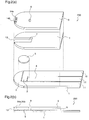
- Figure 8 illustrates an exploded perspective view and a cross-sectional view of the biosensor disclosed in Patent Document 1.
- reference numeral 1 denotes a first insulating substrate, and a measurement electrode 2, a counter electrode 3, and a detector electrode 4, which comprise an electric conducting material, are formed on the first insulating substrate 1.
- the conventional biosensor 800 is formed by bonding the first insulating substrate 1, a spacer 6, and a second insulating substrate 8 together, and a capillary 7 is formed by existence of a notch in the spacer 6.
- a test sample is introduced into the capillary 7 from its front end by a sample supply port 13 that is formed by the bonding and an air hole 9 formed through the insulating substrate 1.
- the measurement electrode 2, the counter electrode 3, and the detector electrode 4 which are formed on the first insulating substrate 1 are exposed in the capillary 7, and a and a reagent layer 5 is formed in a position opposed to these electrodes.
- a measurement instrument (not shown) having terminals to be connected to leads 10, 11, and 12 of the electrodes is inserted in the biosensor before introduction of blood, and variation in the electric characteristics which occurs due to a reaction of the blood with the reagent is detected between the measurement electrode 2 and the counter electrode 3 after introduction of blood, thereby measuring a glucose concentration.
- Patent Document 1 Japanese Published Patent Application No.2002-168821 ).
- US 2002/100685 A1 describes a biosensor comprising first and second substrates with a sample supply port at one end of both substrates and having a capillary space between the substrates into which the sample is to be introduced, as well as a vent hole.
- Figure 9 shows a state where blood is aspirated in the conventional biosensor.
- the difference in the shapes between the first insulating substrate and the second insulating substrate may be further increased to prevent the fingertip from closing the sample supply port, this is a distant idea.
- the reason is as follows. If the difference in the shapes is increased too much, not only the blood stored inside the capillary but also the blood stored outside the capillary increases, and more blood is required conversely.
- the present invention is made to solve the above-described problems and has for its object to provide a biosensor having a construction that can reliably collect a sample solution into a capillary even when the quantity of the sample solution is very small.
- a biosensor which has a capillary structure and performs measurement with a very small quantity of sample is constituted as described above, even when a sample supply port is closed up by elastic skin such as fingertip, brachial region, or abdominal region of a test subject, it is possible to perform reliable aspiration of the sample solution from an auxiliary sample supply port into the capillary.
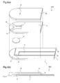
- Figure 1 illustrates an exploded perspective view and a cross-sectional view of a biosensor 100 according to a first embodiment of the present invention.
- reference numeral 1 denotes a first insulating substrate having a portion near a front end being formed approximately in a semicircular shape, and a portion that follows the front end to reach an rear end being formed in a rectangle.
- a measurement element 2, a counter electrode 3, and a detector electrode 4 which are composed of an electric conducting material are formed on the first insulating substrate 1.
- Reference numeral 8 denotes a second insulating substrate which is formed in a shape similar to that of the first insulating substrate 1
- reference numeral 6 denotes a spacer which is disposed between the first insulating substrate 1 and the second insulating substrate 8 and is formed in a shape similar to those of the both insulating substrates
- reference numeral 7 denotes a capillary which is formed so as to form an approximately rectangle convex portion in the vicinity of the front end of the spacer, along the longitudinal direction of the spacer.
- the biosensor 100 is formed by bonding the first insulating substrate 1, the spacer 6, and the second insulating substrate 8 together, and the capillary 7 is formed by existence of the above-mentioned notch in the spacer 6.
- a test sample is introduced into the capillary 7 by a sample supply port 13 that is formed by the bonding, and an air hole 9 that is provided through the first insulating substrate 1 in a position opposed to a rear end of the capillary 7.
- reference numerals 10, 11, and 12 denote leads of the measurement electrode 2, the counter electrode 3, and the detector electrode 4, respectively, which correspond to the rear end portions of the respective electrodes disposed on the first insulating substrate 1, and reference numeral 13 denotes a sample supply port which is formed by that a forward space portion of the capillary 7 is sandwiched by the first and second insulating substrates 1 and 8.
- the measurement electrode 2, the counter electrode 3, and the detector electrode 4 formed on the first insulating substrate 1 are exposed in the capillary 7, and a reagent layer 5 is disposed in a position opposed to these electrodes.
- the detector electrode 4 functions as an electrode for detecting a shortage in the quantity of the sample, it may be used as a reference electrode or a portion of the counter electrode.
- the respective electrodes 2, 3, and 4 are disposed on the first insulating substrate 1, these electrodes may be partially disposed on the opposed second insulating substrate 8 as well as on the first insulating substrate 1.
- Preferable materials of the first insulating substrate 1, the spacer 6, and the second insulating substrate 8 include polyethylene terephthalate, polycarbonate, and polyimide.
- the thicknesses of the first and second insulating substrates are desired to be 0.1 to 5.0mm.
- the electric conducting material constituting the respective electrodes 2, 3, and 4 may include a single substance such as a noble metal (gold, platinum, or palladium) or carbon, or a complex substrate such as carbon paste or a noble metal paste. Sputtering or the like is adopted for the former substance while screen printing or the like is adopted for the latter substance, thereby easily forming the electric conducting layer on the first insulating substrate 1 or the second insulating substrate 8.
- the respective electrodes when forming the respective electrodes, initially an electric conducting layer is formed on the entire surface or a portion of the first insulating substrate 1 or the second insulating substrate 8 by the above-mentioned sputtering or screen printing, and then slits are formed in the electric conducting layer using a laser or the like, thereby fabricating the separated electrodes.
- the respective electrodes can be similarly produced by screen printing or sputtering using a print board or a mask board on which electrode patterns have already been formed.
- the reagent layer 5 including enzyme, electron carrier, hydrophilic macromolecule, and the like is formed on the electrodes 2, 3, and 4.
- the enzyme may be any of glucose oxidase, lactate oxidase, cholesterol oxidase, cholesterol esterase, uricase, ascorbate oxidase, bilirubin oxidase, glucose dehydrogenase, and lactate dehydrogenase.
- the electron carrier may be any of potassium ferricyanide, p-benzoquinone and its derivative, phenazine methosulfate, methylene blue, and ferrocene and its derivative.
- the hydrophilic macromolecule may be any of carboxymethyl cellulose, hydroxyethyl cellulose, hydroxypropyl cellulose, methyl cellulose, ethyl cellulose, ethylhydroxyethyl cellulose, carboxymethylethyl cellulose, polyvinyl alcohol, polyvinylpyrrolidone, polyamino acid such as polylysine, polystyrene sulfonate, gelatine and its derivative, acrylic acid and its salt, and agarose gel and its derivative.
- the capillary 7 to which blood is to be supplied is formed by bonding the first insulating substrate 1 and the second insulating substrate 8 with the spacer 6 between them.
- the sample supply port 13 through which the blood is to be introduced into the capillary 7 is opened at the ends of the first insulating substrate 1 and the second insulating substrate 8.
- the thickness of the spacer 6 is 0.025 to 0.5mm
- the width of the capillary 7 is 0.1 to 10mm
- the volume of the capillary 7 is 0.1 to 5 ⁇ L.
- the construction of the first embodiment is characterized by that an auxiliary sample supply port 14 penetrating through the second insulating substrate 8 on the capillary 7 is provided. After this auxiliary sample supply port 14 is formed through the second insulating substrate 8, the second insulating substrate 8 is bonded to the first insulating substrate 1 and the spacer 6, thereby completing the biosensor.
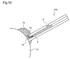
- the auxiliary sample supply port 14 is provided, even when the sample supply port 13 is closed up with a finger chip when applying the blood and thereby supply of the blood from the sample supply port 13 is blocked, the blood can be introduced into the capillary from the auxiliary sample supply port 14 provided through the second insulating substrate 8 as shown in figure 10 , whereby the capillary 7 can be completely filled with the blood.
- This auxiliary sample supply port 14 is desired to be provided in a position to which the sample solution is always attached when the sample solution is supplied.
- a description will be given of the position, size, shape, and number of the auxiliary sample supply port 14.
- the distance between the sample supply port 13 and the auxiliary sample supply port 14, i.e., the size of A shown in the cross-sectional view of figure 1(b) is desirably at least 0.05 to 5.0mm.
- the distance is smaller than 0.05mm, there is a possibility that the two supply ports might be connected and the effect as the auxiliary sample supply port is reduced.
- the distance is larger than 5.0mm, it becomes difficult to apply the sample to the sample supply port 13 and to the auxiliary sample supply port 14 simultaneously.
- the area of the auxiliary sample supply port 14 is desired to be 0.01 to 3.0mm 2 .
- the auxiliary sample supply port 14 lacks the ability of aspirating the sample solution, and thereby the supply speed is reduced or the supply is stopped halfway.
- the area is larger than 3.0mm 2 , the size of the capillary must be increased, which leads to an increase in the quantity of the sample, and therefore, this is a distant idea.
- auxiliary sample supply port 14 It is desired to process the auxiliary sample supply port 14 using a laser. Although press cutting, die cutting, and Thomson cutting are also applicable for processing the supply port, laser processing is most preferable because it enables microfabrication.
- a plurality of auxiliary sample supply ports 14 may be provided on the second insulating substrate 8, with favorable effects. Further, the shape of the auxiliary sample supply port 14 is not restricted to that mentioned above so long as the above-mentioned conditions are satisfied. For example, it may be circular, oval, linear, rectangular, triangular, or the like.
- auxiliary sample supply port 14 is provided on the second insulating substrate 8, it may be provided on the first insulating substrate 1. At this time, the position, shape, and size of the auxiliary sample supply port 14 are identical to those mentioned above.
- the shape of the biosensor 100 is not restricted to that of the first embodiment shown in figure 1 , and the same effects as mentioned above can be achieved even when the biosensor has a shape according to a modification shown in figure 2 or a shape according to another modification shown in figure 3 .
- a biosensor 200 according to a modification of the first embodiment shown in figure 2 has plural auxiliary sample supply ports 14a and 14b.
- a biosensor 300 according to another modification of the first embodiment shown in figure 3 has a rectangular auxiliary sample supply port 14.
- figure 4 shows a biosensor 400 according to still another modification of the first embodiment.
- This biosensor 400 is constituted such that the first insulating substrate 1 and the second insulating substrate 8 which form the capillary 7 are bonded together shifted from each other so that the end portions thereof viewed planarly are located in different positions.
- the second insulating substrate 8 and the spacer 6 are protruded by 0.1 to 1.0mm toward the sample supply port 13 with respect to the first insulating substrate 1.
- biosensors 200, 300, and 400 shown in figures 2 , 3 , and 4 also achieve the same effects as the biosensor 100 shown in figure 1 .
- Electrodes 2, 3, and 4 and the reagent layer 5 for electrochemically analyzing a specific substance in the sample solution are provided inside the capillary 7, it is desired that these electrodes 2, 3, 4 and the reagent layer 5 are not disposed at a position on the first insulating substrate 1 directly beneath the auxiliary sample supply port 14.
- auxiliary sample supply port 14 is disposed above the electrodes 2, 3, and 4, the sample solution on the electrodes is likely to vary, and this variation may cause undesirable variation in the response value.
- biosensors 200, 300, and 400 shown in figures 2 , 3 , and 4 also achieve the same effects as the biosensor 100 shown in figure 1 .
- biosensors 100, 200, 300, and 400 it is desired that a surface-activating treatment is applied to the entirety or a portion of the inner wall of the capillary 7. Thereby, even when the area of the sample supply port is small, the capillary can speedily aspirate the sample solution.
- a surface-activating treatment is applied to the inner side of the auxiliary sample supply port 14, or the entire inner wall of the capillary, or a portion of the inner wall of the capillary in the vicinity of the auxiliary sample supply port.
- the surface-activating treatment includes coating of a nonionic, cationic, anionic, or zwitterionic surfactant, corona discharge treatment, and physical processing to form fine concavities and convexities on the surface.
- the sample solution is speedily supplied from the auxiliary sample supply port 14, and thereby the sample solution is aspirated into the capillary accurately and easily.
- Figure 5 illustrates an exploded perspective view and a cross-sectional view of a biosensor 500 according to a second embodiment of the present invention.
- auxiliary sample supply ports 14 are provided on both the first insulating substrate 1 and the second insulating substrate 8.
- auxiliary sample supply ports 14 are provided on the two insulating substrates 1 and 8, respectively, even if the sample is applied from a biased angle, the sample can be reliably aspirated into the space 6.
- auxiliary sample supply ports 14 may be provided on the respective substrates with the same effects as mentioned above.
- auxiliary sample supply port 14 is not particularly restricted, and it may be circular, oval, linear, rectangular, or triangular.
- Figure 6 illustrates an exploded perspective view and a cross-sectional view of a biosensor 600 according to a third embodiment of the present invention.
- the capillary 7 branches in a Y shape in the vicinity of the front end, and one of the branches serves as the sample supply port 13 while the other serves as the auxiliary sample supply port 14.
- the spacer 6 is provided with the two sample supply ports, the same effects as those of the first and second embodiments are achieved. Further, since the sample supply port 13 and the auxiliary sample supply port 14 can be simultaneously patterned in the spacer 6, the number of process steps in the sensor fabrication can be reduced.
- a biosensor constituted as mentioned below is used as an example.
- a palladium thin film having a thickess of about 8nm is formed by sputtering over the entire surface of a first insulating substrate comprising polyethylene terephthalate, slits are partially formed in the thin film by using a YAG laser, thereby separately forming a measurement electrode, a counter electrode, and a detector electrode.
- an aqueous solution containing glucose dehydrogenase as an enzyme and potassium ferricyanide as an electron carrier is dropped circularly so as to partially cover the counter electrode and the detector electrode with the measurement electrode being in the center, and then dried, thereby forming a reagent layer.
- a spacer comprising polyethylene terephthalate and a second insulating substrate also comprising polyethylene terephthalate are bonded onto the first insulating substrate.
- a surface-activating treatment is previously applied to the surface of the second insulating substrate on the sample supply port side, and an air hole is formed through the second insulating substrate, and further, an auxiliary sample supply port is formed at a position apart by 0.2mm from the sample supply port.
- Table 1 shows the test results.
- auxiliary sample supply port when the area of the auxiliary sample supply port is 0.005mm 2 , aspiration speed is lowered when the finger is pressed against the supply port. It is estimated that the area of the auxiliary sample supply port is small and insufficient to introduce the blood into the capillary.
- auxiliary sample supply port When the area of the auxiliary sample supply port is equal to or larger than 0.01mm 2 , speedily aspiration is carried out even when the finger is pressed against the supply port. It is estimated that even when the sample supply port is closed up and supply of the sample solution is rate-limited, the sample solution is speedily supplied from the auxiliary sample supply port.
- auxiliary sample supply port when the area of the auxiliary sample supply port is equal to or larger than 3mm 2 , it is difficult to make the sample contact the entirety of the auxiliary supply port for the same reason as mentioned above, and the auxiliary supply port cannot perform its function.
- a biosensor according to the present invention is applicable to a blood glucose sensor, a cholesterol sensor, a lactic acid sensor, an alcohol sensor, an amino acid sensor, a fructose sensor, and a sucrose sensor, which collect a very small quantity of sample solution into a capillary and perform analysis.
- samples used for the analysis may include liquid samples such as blood, urine, sweat, saliva, drinkable water, and sewage water.
Description
- The present invention relates to a biosensor for analyzing a specific component in a sample solution, and more particularly, to a biosensor which collects a small amount of sample solution by capillary phenomenon onto a small-size test specimen, and analyzes the sample solution.
- A biosensor is a sensor for determining a quantity of a base substance in a sample solution, which utilizes a molecule recognizing ability of a biological material such as micro-organism, enzyme, antibody, DNA, RNA or the like to employ the biological material as a molecule discrimination element. To be specific, the biosensor determines a quantity of a base substance contained in a sample solution by utilizing a reaction which occurs when a biological material recognizes an objective substrate, such as consumption of oxygen due to respiration of a micro-organism, enzyme reaction, light emission, and the like. Among various kinds of biosensors, an enzyme sensor has come into practical use. For example, an enzyme sensor as a biosensor for glucose, lactic acid, cholesterol, or amino acid has been utilized for medical analysis and food industry. In this enzyme sensor, an electron carrier is reduced by electrons that are generated due to a reaction between a base substance included in a sample solution as an analyte and enzyme or the like, and a measurement unit electrochemically measures a reduction quantity of the electron carrier, thereby performing quantitative analysis for the sample.
- There have been proposed various types of biosensors. For example, as a biosensor that facilitates measurement of blood glucose level, there is a biosensor comprising a first insulating substrate on which a pair of electrodes and a reagent layer are formed, a second insulating substrate bonded to the first insulating substrate via a spacer, and a capillary for collecting a sample solution, which is provided between the both insulating substrates. The biosensor is constituted such that blood obtained by puncturing human body is introduced by capillary phenomenon into the capillary from a sample supply port that opens at one ends of the both substrates.
- In this biosensor, however, there is a possibility that the blood is not successfully introduced into the capillary depending on the angle of the biosensor when the blood is applied onto the sample supply port, and thereby the blood might be attached to the outer surface of the insulating substrate by mistake. In this case, even when the user tries to supply the blood again, the blood attached to the outer surface impedes the user from successfully supplying the blood into the capillary, resulting in faulty measurement and measurement errors.
- In order to solve this problem, the inventors of the present invention have proposed a biosensor in which the ends of the both substrates which constitute the sample supply port are formed in different shapes when viewed planarly so that blood can always be introduced into the capillary successfully without being influenced by the angle of the biosensor when the blood is applied (refer to Patent Document 1).
-
Figure 8 illustrates an exploded perspective view and a cross-sectional view of the biosensor disclosed inPatent Document 1. Infigure 8 ,reference numeral 1 denotes a first insulating substrate, and ameasurement electrode 2, acounter electrode 3, and adetector electrode 4, which comprise an electric conducting material, are formed on the firstinsulating substrate 1. - The
conventional biosensor 800 is formed by bonding the firstinsulating substrate 1, aspacer 6, and a secondinsulating substrate 8 together, and acapillary 7 is formed by existence of a notch in thespacer 6. A test sample is introduced into thecapillary 7 from its front end by asample supply port 13 that is formed by the bonding and anair hole 9 formed through theinsulating substrate 1. - Further, the
measurement electrode 2, thecounter electrode 3, and thedetector electrode 4 which are formed on the firstinsulating substrate 1 are exposed in thecapillary 7, and a and areagent layer 5 is formed in a position opposed to these electrodes. - A measurement instrument (not shown) having terminals to be connected to leads 10, 11, and 12 of the electrodes is inserted in the biosensor before introduction of blood, and variation in the electric characteristics which occurs due to a reaction of the blood with the reagent is detected between the
measurement electrode 2 and thecounter electrode 3 after introduction of blood, thereby measuring a glucose concentration. - Patent Document 1:
Japanese Published Patent Application No.2002-168821 -
US 2002/100685 A1 describes a biosensor comprising first and second substrates with a sample supply port at one end of both substrates and having a capillary space between the substrates into which the sample is to be introduced, as well as a vent hole. - By the way, in the blood glucose measurement in recent years, it is desired to minimize the quantity of blood to be collected in order to reduce pain of diabetic patient as much as possible. Therefore, development of a biosensor in which the size of the capillary for collecting blood and the size of the sample supply port are further reduced has been progressed.
- However, such miniaturization in the conventional biosensor has caused a problem that the sample supply port is easily closed up when a deformable object such as a finger chip is pressed thereto.
-
Figure 9 shows a state where blood is aspirated in the conventional biosensor. - As shown in
figure 9(a) , when thesample supply port 13 is closed up by a fingertip, supply of blood is interrupted, and the blood is not completely filled in thecapillary 7 but stops in the middle of thecapillary 7. Then, shortage of sample quantity occurs, which may cause incapable measurement, or display of incorrect results. Further, even when the capillary is completely filled with the blood by rightly separating the finger as shown infigure 9(b) after the finger has once closed thesample supply port 13, there occurs a difference in dissolution of the reagent layer due to the initially introduced blood, resulting in variations in measurement, and therefore, accurate measurement cannot be carried out. - Although it might be considered that the difference in the shapes between the first insulating substrate and the second insulating substrate may be further increased to prevent the fingertip from closing the sample supply port, this is a distant idea. The reason is as follows. If the difference in the shapes is increased too much, not only the blood stored inside the capillary but also the blood stored outside the capillary increases, and more blood is required conversely.
- The present invention is made to solve the above-described problems and has for its object to provide a biosensor having a construction that can reliably collect a sample solution into a capillary even when the quantity of the sample solution is very small.
- In order to solve the above-mentioned problems, there is provided a biosensor according to
claim 1. - According to the present invention, since a biosensor which has a capillary structure and performs measurement with a very small quantity of sample is constituted as described above, even when a sample supply port is closed up by elastic skin such as fingertip, brachial region, or abdominal region of a test subject, it is possible to perform reliable aspiration of the sample solution from an auxiliary sample supply port into the capillary.
-
-
Figure 1 illustrates an exploded perspective view and a cross-sectional view of abiosensor 100 according to a first embodiment of the present invention. -
Figure 2 illustrates an exploded perspective view and a cross-sectional view of abiosensor 200 according to a modification of the first embodiment. -
Figure 3 illustrates an exploded perspective view and a cross-sectional view of abiosensor 300 according to another modification of the first embodiment. -
Figure 4 illustrates an exploded perspective view and a cross-sectional view of abiosensor 400 according to still another modification of the first embodiment. -
Figure 5 illustrates an exploded perspective view and a cross-sectional view of abiosensor 500 according to a second embodiment of the present invention. -
Figure 6 illustrates an exploded perspective view and a cross-sectional view of abiosensor 600 according to a third embodiment of the present invention. -
Figure 7 illustrates an exploded perspective view and a cross-sectional view of abiosensor 700 according to a comparison example of the present invention. -
Figure 8 illustrates an exploded perspective view and a cross-sectional view of theconventional biosensor 800. -
Figure 9 is a cross-sectional view illustrating a state where blood is aspirated in theconventional biosensor 800. -
Figure 10 is a cross-sectional view illustrating a state where blood is aspirated in thebiosensor 100 according to the first embodiment. -
- 100 ... biosensor
- 200 ... biosensor
- 300 ... biosensor
- 400 ... biosensor
- 500 ... biosensor
- 600 ... biosensor
- 700 ... biosensor
- 800 ... biosensor
- 1 ... first insulating substrate
- 2 ... measurement electrode
- 3 ... counter electrode
- 4 ... detector electrode
- 5 ... reagent layer
- 6 ... spacer
- 7 ... capillary
- 8 ... second insulating substrate
- 9 ... air hole
- 10 ... lead
- 11 ... lead
- 12 ... lead
- 13 ... sample supply port
- 14 ... auxiliary sample supply port
- 15 ... notch
- 16 ... blood
- 17 ... fingertip
- Hereinafter, embodiments of a biosensor according to the present invention will be described taking a blood glucose sensor as an example with reference to the drawings.
-
Figure 1 illustrates an exploded perspective view and a cross-sectional view of abiosensor 100 according to a first embodiment of the present invention. - In the
biosensor 100 shown infigure 1 ,reference numeral 1 denotes a first insulating substrate having a portion near a front end being formed approximately in a semicircular shape, and a portion that follows the front end to reach an rear end being formed in a rectangle. Ameasurement element 2, acounter electrode 3, and adetector electrode 4 which are composed of an electric conducting material are formed on the first insulatingsubstrate 1.Reference numeral 8 denotes a second insulating substrate which is formed in a shape similar to that of the first insulatingsubstrate 1,reference numeral 6 denotes a spacer which is disposed between the first insulatingsubstrate 1 and the second insulatingsubstrate 8 and is formed in a shape similar to those of the both insulating substrates, andreference numeral 7 denotes a capillary which is formed so as to form an approximately rectangle convex portion in the vicinity of the front end of the spacer, along the longitudinal direction of the spacer. - The
biosensor 100 is formed by bonding the first insulatingsubstrate 1, thespacer 6, and the second insulatingsubstrate 8 together, and thecapillary 7 is formed by existence of the above-mentioned notch in thespacer 6. A test sample is introduced into thecapillary 7 by asample supply port 13 that is formed by the bonding, and anair hole 9 that is provided through the first insulatingsubstrate 1 in a position opposed to a rear end of thecapillary 7. - Further,
reference numerals measurement electrode 2, thecounter electrode 3, and thedetector electrode 4, respectively, which correspond to the rear end portions of the respective electrodes disposed on the first insulatingsubstrate 1, andreference numeral 13 denotes a sample supply port which is formed by that a forward space portion of thecapillary 7 is sandwiched by the first and secondinsulating substrates - Further, the
measurement electrode 2, thecounter electrode 3, and thedetector electrode 4 formed on the first insulatingsubstrate 1 are exposed in thecapillary 7, and areagent layer 5 is disposed in a position opposed to these electrodes. - When performing measurement using the
biosensor 100 of the first embodiment, variations in the electric characteristics between themeasurement electrode 2 and thecounter electrode 3 are detected with thebiosensor 100 being inserted in a measurement instrument (not shown) having terminals which are to be connected to theleads respective electrodes - While the
detector electrode 4 functions as an electrode for detecting a shortage in the quantity of the sample, it may be used as a reference electrode or a portion of the counter electrode. - While in
figure 1 therespective electrodes substrate 1, these electrodes may be partially disposed on the opposed second insulatingsubstrate 8 as well as on the first insulatingsubstrate 1. - Preferable materials of the first insulating
substrate 1, thespacer 6, and the second insulatingsubstrate 8 include polyethylene terephthalate, polycarbonate, and polyimide. The thicknesses of the first and second insulating substrates are desired to be 0.1 to 5.0mm. - Further, the electric conducting material constituting the
respective electrodes substrate 1 or the second insulatingsubstrate 8. - Further, when forming the respective electrodes, initially an electric conducting layer is formed on the entire surface or a portion of the first insulating
substrate 1 or the second insulatingsubstrate 8 by the above-mentioned sputtering or screen printing, and then slits are formed in the electric conducting layer using a laser or the like, thereby fabricating the separated electrodes. Alternatively, the respective electrodes can be similarly produced by screen printing or sputtering using a print board or a mask board on which electrode patterns have already been formed. - The
reagent layer 5 including enzyme, electron carrier, hydrophilic macromolecule, and the like is formed on theelectrodes - The hydrophilic macromolecule may be any of carboxymethyl cellulose, hydroxyethyl cellulose, hydroxypropyl cellulose, methyl cellulose, ethyl cellulose, ethylhydroxyethyl cellulose, carboxymethylethyl cellulose, polyvinyl alcohol, polyvinylpyrrolidone, polyamino acid such as polylysine, polystyrene sulfonate, gelatine and its derivative, acrylic acid and its salt, and agarose gel and its derivative.
- Next, the
capillary 7 to which blood is to be supplied is formed by bonding the first insulatingsubstrate 1 and the second insulatingsubstrate 8 with thespacer 6 between them. Thesample supply port 13 through which the blood is to be introduced into thecapillary 7 is opened at the ends of the first insulatingsubstrate 1 and the second insulatingsubstrate 8. - In this first embodiment, the thickness of the
spacer 6 is 0.025 to 0.5mm, the width of thecapillary 7 is 0.1 to 10mm, and the volume of thecapillary 7 is 0.1 to 5µL. - The construction of the first embodiment is characterized by that an auxiliary
sample supply port 14 penetrating through the second insulatingsubstrate 8 on thecapillary 7 is provided. After this auxiliarysample supply port 14 is formed through the second insulatingsubstrate 8, the second insulatingsubstrate 8 is bonded to the first insulatingsubstrate 1 and thespacer 6, thereby completing the biosensor. - Since the auxiliary
sample supply port 14 is provided, even when thesample supply port 13 is closed up with a finger chip when applying the blood and thereby supply of the blood from thesample supply port 13 is blocked, the blood can be introduced into the capillary from the auxiliarysample supply port 14 provided through the second insulatingsubstrate 8 as shown infigure 10 , whereby thecapillary 7 can be completely filled with the blood. - This auxiliary
sample supply port 14 is desired to be provided in a position to which the sample solution is always attached when the sample solution is supplied. Hereinafter, a description will be given of the position, size, shape, and number of the auxiliarysample supply port 14. - The distance between the
sample supply port 13 and the auxiliarysample supply port 14, i.e., the size of A shown in the cross-sectional view offigure 1(b) , is desirably at least 0.05 to 5.0mm. When the distance is smaller than 0.05mm, there is a possibility that the two supply ports might be connected and the effect as the auxiliary sample supply port is reduced. Further, in the recent biosensor which is desired to minimize the quantity of blood, if the distance is larger than 5.0mm, it becomes difficult to apply the sample to thesample supply port 13 and to the auxiliarysample supply port 14 simultaneously. - The area of the auxiliary
sample supply port 14 is desired to be 0.01 to 3.0mm2. When the area is smaller than 0.01mm2, the auxiliarysample supply port 14 lacks the ability of aspirating the sample solution, and thereby the supply speed is reduced or the supply is stopped halfway. When the area is larger than 3.0mm2, the size of the capillary must be increased, which leads to an increase in the quantity of the sample, and therefore, this is a distant idea. - It is desired to process the auxiliary
sample supply port 14 using a laser. Although press cutting, die cutting, and Thomson cutting are also applicable for processing the supply port, laser processing is most preferable because it enables microfabrication. - A plurality of auxiliary
sample supply ports 14 may be provided on the second insulatingsubstrate 8, with favorable effects. Further, the shape of the auxiliarysample supply port 14 is not restricted to that mentioned above so long as the above-mentioned conditions are satisfied. For example, it may be circular, oval, linear, rectangular, triangular, or the like. - Further, while the auxiliary
sample supply port 14 is provided on the second insulatingsubstrate 8, it may be provided on the first insulatingsubstrate 1. At this time, the position, shape, and size of the auxiliarysample supply port 14 are identical to those mentioned above. - Further, the shape of the
biosensor 100 is not restricted to that of the first embodiment shown infigure 1 , and the same effects as mentioned above can be achieved even when the biosensor has a shape according to a modification shown infigure 2 or a shape according to another modification shown infigure 3 . - To be specific, a
biosensor 200 according to a modification of the first embodiment shown infigure 2 has plural auxiliarysample supply ports - Further, a
biosensor 300 according to another modification of the first embodiment shown infigure 3 has a rectangular auxiliarysample supply port 14. - Furthermore,
figure 4 shows abiosensor 400 according to still another modification of the first embodiment. Thisbiosensor 400 is constituted such that the first insulatingsubstrate 1 and the second insulatingsubstrate 8 which form thecapillary 7 are bonded together shifted from each other so that the end portions thereof viewed planarly are located in different positions. - That is, in
figure 4 , the second insulatingsubstrate 8 and thespacer 6 are protruded by 0.1 to 1.0mm toward thesample supply port 13 with respect to the first insulatingsubstrate 1. - The
biosensors figures 2 ,3 , and4 also achieve the same effects as thebiosensor 100 shown infigure 1 . - When the
electrodes reagent layer 5 for electrochemically analyzing a specific substance in the sample solution are provided inside thecapillary 7, it is desired that theseelectrodes reagent layer 5 are not disposed at a position on the first insulatingsubstrate 1 directly beneath the auxiliarysample supply port 14. - If the auxiliary
sample supply port 14 is disposed above theelectrodes - The
biosensors figures 2 ,3 , and4 also achieve the same effects as thebiosensor 100 shown infigure 1 . - Further, in the above-mentioned
biosensors capillary 7. Thereby, even when the area of the sample supply port is small, the capillary can speedily aspirate the sample solution. - Further, it is desired that a surface-activating treatment is applied to the inner side of the auxiliary
sample supply port 14, or the entire inner wall of the capillary, or a portion of the inner wall of the capillary in the vicinity of the auxiliary sample supply port. - When a surface-activating treatment is applied to the inner side of the auxiliary
sample supply port 14 or the inner wall of the capillary, aspiration of the sample solution is quickly started as soon as the sample solution contacts the auxiliarysample supply port 14, and thereby the capillary is filled with the sample solution before the supply port is closed up by a fingertip or the like. - The surface-activating treatment includes coating of a nonionic, cationic, anionic, or zwitterionic surfactant, corona discharge treatment, and physical processing to form fine concavities and convexities on the surface.
- As described above, according to the biosensor of the first embodiment, even when the
sample supply port 13 is closed up while the sample solution is being supplied, the sample solution is speedily supplied from the auxiliarysample supply port 14, and thereby the sample solution is aspirated into the capillary accurately and easily. -
Figure 5 illustrates an exploded perspective view and a cross-sectional view of abiosensor 500 according to a second embodiment of the present invention. - In the
biosensor 500 of the second embodiment shown infigure 5 , auxiliarysample supply ports 14 are provided on both the first insulatingsubstrate 1 and the second insulatingsubstrate 8. - Since the auxiliary
sample supply ports 14 are provided on the two insulatingsubstrates space 6. - Further, as described in the first embodiment, plural auxiliary
sample supply ports 14 may be provided on the respective substrates with the same effects as mentioned above. - Further, the shape of the auxiliary
sample supply port 14 is not particularly restricted, and it may be circular, oval, linear, rectangular, or triangular. -
Figure 6 illustrates an exploded perspective view and a cross-sectional view of abiosensor 600 according to a third embodiment of the present invention. - In the
biosensor 600 of the third embodiment shown infigure 6 , the capillary 7 branches in a Y shape in the vicinity of the front end, and one of the branches serves as thesample supply port 13 while the other serves as the auxiliarysample supply port 14. - In this third embodiment, since the
spacer 6 is provided with the two sample supply ports, the same effects as those of the first and second embodiments are achieved. Further, since thesample supply port 13 and the auxiliarysample supply port 14 can be simultaneously patterned in thespacer 6, the number of process steps in the sensor fabrication can be reduced. - Hereinafter, a specific example of the present invention will be described in detail.
- A biosensor constituted as mentioned below is used as an example.
- After a palladium thin film having a thickess of about 8nm is formed by sputtering over the entire surface of a first insulating substrate comprising polyethylene terephthalate, slits are partially formed in the thin film by using a YAG laser, thereby separately forming a measurement electrode, a counter electrode, and a detector electrode.
- Thereafter, an aqueous solution containing glucose dehydrogenase as an enzyme and potassium ferricyanide as an electron carrier is dropped circularly so as to partially cover the counter electrode and the detector electrode with the measurement electrode being in the center, and then dried, thereby forming a reagent layer. Further, a spacer comprising polyethylene terephthalate and a second insulating substrate also comprising polyethylene terephthalate are bonded onto the first insulating substrate.
- A surface-activating treatment is previously applied to the surface of the second insulating substrate on the sample supply port side, and an air hole is formed through the second insulating substrate, and further, an auxiliary sample supply port is formed at a position apart by 0.2mm from the sample supply port.
- The above-mentioned members are bonded together to complete a biosensor having a capillary into which blood is introduced, which has the same construction as that shown in
figure 1 . - In order to confirm the effects of the present invention, there are fabricated fourteen types of sensors as follows:
- a
conventional biosensor 800 shown infigure 8 ((1)); -
biosensors 100 according to the first embodiment shown infigure 1 , wherein the aperture areas of the auxiliarysample supply ports 14 are 0.005mm2, 0.010mm2, 0.030mm2, and 0.100mm2, respectively ((2), (3), (4), (5)); -
biosensors 200 according to a modification of the first embodiment shown infigure 2 , wherein the number of the auxiliarysample supply ports 14 is two (area: 0.003mm2), two (area: 0.050mm2), four (area: 0.01mm2), and nine (area: 0.01mm2), respectively ((6), (7)), (8), (9)); - a
biosensor 300 according to another modification of the first embodiment shown infigure 3 , wherein the auxiliarysample supply port 14 is rectangle in shape ((10)); - a
biosensor 500 according to the second embodiment shown infigure 5 , wherein the auxiliarysample supply ports 14 are formed on both the first insulatingsubstrate 1 and the second insulating substrate 8 ((11)); - a biosensor having an auxiliary sample supply port on the first insulating substrate ((12));
- a
biosensor 600 according to the third embodiment shown infigure 6 , wherein thecapillary 7 is Y-shaped ((13)); and - a
biosensor 700 as a sensor for comparison shown infigure 7 , wherein a groove-shapedslit 15 is formed at a front end of a secondinsulating substrate 8, and asample supply port 13 and an auxiliary sample supply port formed by theslit 15 are connected ((14)). - Then, 2 µL of blood which is sufficient to completely fill the sample supply port of the biosensor of this example is collected on a fingertip, the finger is pressed against the sample supply port, and the blood aspiration state when the sample supply port is closed up is checked.
-
Table 1 sample area of AUX supply port number of AUX supply port result 1 2 3 4 5 conventional sensor (1) - 0 × × × × × AUX supply port on 2nd insulating substrate (2) 0.005 mm 21 Δ Δ × Δ ○ (3) 0.010 mm 21 ○ ○ ○ ○ ○ (4) 0.030 mm 21 ○ ○ ○ ○ ○ (5) 0.100 mm 21 ○ ○ ○ ○ ○ (6) 0.003 mm 22 Δ Δ × Δ Δ (7) 0.05 mm 22 ○ ○ ○ ○ ○ invention sensor (8) 0.01 mm 24 ○ ○ ○ ○ ○ (9) 0.01 mm 29 ○ ○ ○ ○ ○ rectangular AUX supply port ( Fig.3 )(10) 0.01 mm 21 ○ ○ ○ ○ ○ AUX supply ports on both insulating substrates ( Fig.5 )(11) 0.01 mm 22 ○ ○ ○ ○ ○ AUX supply port on 1st insulating substrate (12) 0.01 mm 21 ○ ○ ○ ○ ○ Y-shaped capillary( Fig.6 )(13) 0.15 mm 21 ○ ○ ○ ○ ○ compa rison sensor main supply port short-circuited with AUX supply port ( Fig.7 )(14) 0.010 mm 20 × × × Δ Δ ○: Speedily and accurate aspiration is performed even when finger is pressed.
Δ: Aspiration is lowered in speed or stopped halfway when finger is pressed.
×: Aspiration is stopped when finger is pressed. - As is evident from Table 1, in the conventional biosensor having no auxiliary sample supply port, when the finger is pressed against the sample supply port, aspiration is stopped in all the results. This is because the sample supply port is closed up by pressing an elastic object such as a fingertip, and thereby supply of the sample solution is prevented.
- Further, when the area of the auxiliary sample supply port is 0.005mm2, aspiration speed is lowered when the finger is pressed against the supply port. It is estimated that the area of the auxiliary sample supply port is small and insufficient to introduce the blood into the capillary.
- When the area of the auxiliary sample supply port is equal to or larger than 0.01mm2, speedily aspiration is carried out even when the finger is pressed against the supply port. It is estimated that even when the sample supply port is closed up and supply of the sample solution is rate-limited, the sample solution is speedily supplied from the auxiliary sample supply port.
- When plural auxiliary sample supply ports are provided, the same effects can be obtained so long as the total of the areas of the supply ports is equal to or larger than 0.01mm2.
- In the case where the main supply port and the auxiliary supply port are connected and a groove-shaped slit is formed at the front end of the second insulating substrate as shown in
figure 7 , aspiration is stopped or lowered in speed when the finger is pressed against the main supply port, even though the area of the groove is 0.01mm2. It is estimated that when the sample supply port and the auxiliary supply port are connected, the finger pressed against the sample supply port undesirably adheres tightly to the inside of the auxiliary supply port, and thereby the auxiliary supply port becomes incapable of performing its function. - On the other hand, favorable results can be obtained with respect to the biosensor having a rectangle auxiliary sample supply port (refer to
figure 3 ), the biosensor having auxiliary sample supply ports on both the first and secondinsulating substrates 1 and 2 (refer tofigure 5 ), the biosensor having an auxiliary sample supply port on the insulatingsubstrate 1, and the biosensor having a Y-shaped capillary (refer tofigure 6 ). - When performing measurement with a very small quantity of sample solution as in this example, if the sample supply port and the auxiliary sample supply port are separated by 5mm or more, it is difficult to make the sample contact these ports simultaneously, and favorable effects cannot be obtained.
- Also when the area of the auxiliary sample supply port is equal to or larger than 3mm2, it is difficult to make the sample contact the entirety of the auxiliary supply port for the same reason as mentioned above, and the auxiliary supply port cannot perform its function.
- A biosensor according to the present invention is applicable to a blood glucose sensor, a cholesterol sensor, a lactic acid sensor, an alcohol sensor, an amino acid sensor, a fructose sensor, and a sucrose sensor, which collect a very small quantity of sample solution into a capillary and perform analysis. Further, samples used for the analysis may include liquid samples such as blood, urine, sweat, saliva, drinkable water, and sewage water.
Claims (8)
- A biosensor comprising a spacer layer (6) disposed between a first insulating substrate (1) and a second insulating substrate (8), and forming a capillary (7) in front end of the spacer layer (6), a sample supply port (13) which opens at a front end of both substrates and adapted to be in contact with a sample solution, the capillary (7) communicated with the sample supply port (13), into which the sample solution is introduced by capillary (7) phenomenon, and an air hole (9) which is positioned at an end of the capillary (7) and communicated with air inside the capillary (7),
wherein at least one auxiliary sample supply port (14) communicated with said capillary (7) is located at a distance between said auxiliary sample supply port (14) and said sample supply port (13) that is 0.05 and 5 mm, such that, the sample solution is introduced into the capillary (7) through said at least one auxiliary sample supply port (14)
characterized in that said auxiliary sample supply port (14) is a through-hole in the first insulating substrate (1) or the second insulating substrate (8) so as to leave a portion of the insulating substrate (1, 8) between the auxiliary sample supply portion (14) and the sample supply port (13). - A biosensor as defined in Claim 1 wherein said auxiliary sample supply ports (14) are formed in both of the first insulating substrate (1) and the second insulating substrate (8).
- A biosensor as defined in Claim 1 wherein a total of aperture areas of said at least one auxiliary sample supply port (14) is 0.01 mm2 to 3 mm2.
- A biosensor as defined in Claim 1 wherein a surface-activating treatment is applied to at least a portion of the surface of the first insulating substrate (1) or the second insulating substrate (8), which portion faces the capillary (7).
- A biosensor as defined in Claim 1 wherein electrodes (2, 3, 4) and a reagent layer (5) for electrochemically analyzing a specific substance in the sample solution are provided on the surface of the first insulating substrate (1) or the second insulating substrate (8), which surface faces the capillary (7).
- A biosensor as defined in Claim 5 wherein the first insulating substrate (1) and the second insulating substrate (8) have different shapes in the position at the end of the biosensor where the sample supply port (13) is formed.
- A biosensor as defined in Claim 6 wherein the electrodes (2, 3, 4) or the reagent layer (5) are/is not provided on the first or second insulating substrate (1, 8) which is opposed to the auxiliary sample supply port (14).
- A biosensor as defined in Claim 1 wherein a surface-activating treatment is applied to an inner wall of the auxiliary sample supply port (14).
Applications Claiming Priority (2)
| Application Number | Priority Date | Filing Date | Title |
|---|---|---|---|
| JP2005184306A JP4501793B2 (en) | 2005-06-24 | 2005-06-24 | Biosensor |
| PCT/JP2006/312665 WO2006137549A1 (en) | 2005-06-24 | 2006-06-23 | Biosensor |
Publications (3)
| Publication Number | Publication Date |
|---|---|
| EP1903334A1 EP1903334A1 (en) | 2008-03-26 |
| EP1903334A4 EP1903334A4 (en) | 2011-12-21 |
| EP1903334B1 true EP1903334B1 (en) | 2016-06-22 |
Family
ID=37570566
Family Applications (1)
| Application Number | Title | Priority Date | Filing Date |
|---|---|---|---|
| EP06767282.4A Active EP1903334B1 (en) | 2005-06-24 | 2006-06-23 | Biosensor |
Country Status (7)
| Country | Link |
|---|---|
| US (2) | US8007645B2 (en) |
| EP (1) | EP1903334B1 (en) |
| JP (1) | JP4501793B2 (en) |
| KR (1) | KR100951741B1 (en) |
| CN (1) | CN101208598B (en) |
| CA (1) | CA2613254C (en) |
| WO (1) | WO2006137549A1 (en) |
Families Citing this family (23)
| Publication number | Priority date | Publication date | Assignee | Title |
|---|---|---|---|---|
| JP2009097877A (en) * | 2007-10-12 | 2009-05-07 | National Institute Of Advanced Industrial & Technology | Biosensor chip |
| JP5178223B2 (en) * | 2008-02-06 | 2013-04-10 | パナソニック株式会社 | Analytical device and analyzer using the same |
| JP5178224B2 (en) * | 2008-02-06 | 2013-04-10 | パナソニック株式会社 | Analytical device and analyzer using the same |
| KR101104400B1 (en) * | 2009-06-02 | 2012-01-16 | 주식회사 세라젬메디시스 | Biosensor for measuring biomaterial |
| JP5698085B2 (en) | 2010-07-12 | 2015-04-08 | アークレイ株式会社 | Biosensor and manufacturing method thereof |
| WO2012131903A1 (en) * | 2011-03-29 | 2012-10-04 | 株式会社テクノメデイカ | Biosensor |
| US8956518B2 (en) | 2011-04-20 | 2015-02-17 | Lifescan, Inc. | Electrochemical sensors with carrier field |
| JP2013257310A (en) * | 2012-05-18 | 2013-12-26 | Arkray Inc | Biosensor |
| US8877023B2 (en) * | 2012-06-21 | 2014-11-04 | Lifescan Scotland Limited | Electrochemical-based analytical test strip with intersecting sample-receiving chambers |
| JPWO2014064978A1 (en) * | 2012-10-22 | 2016-09-08 | 株式会社村田製作所 | Biosensor and manufacturing method thereof |
| EP3163306A4 (en) | 2014-06-30 | 2018-01-24 | Panasonic Healthcare Holdings Co., Ltd. | Substrate for sample analysis, and sample analysis apparatus |
| EP3163307B1 (en) | 2014-06-30 | 2021-03-03 | PHC Holdings Corporation | Substrate for sample analysis, sample analysis device, sample analysis system, and method for removing liquid from liquid that contains magnetic particles |
| WO2016002727A1 (en) | 2014-06-30 | 2016-01-07 | パナソニックヘルスケアホールディングス株式会社 | Substrate for sample analysis, sample analysis device, sample analysis system, and program for sample analysis system |
| JP6588910B2 (en) | 2014-06-30 | 2019-10-09 | Phcホールディングス株式会社 | Sample analysis substrate, sample analysis apparatus, sample analysis system, and program for sample analysis system |
| CA3123430A1 (en) * | 2014-11-03 | 2016-05-12 | F. Hoffmann-La Roche Ag | Electrode arrangements for electrochemical test elements and methods of use thereof |
| US9669408B2 (en) | 2014-11-28 | 2017-06-06 | Htc Corporation | Slight volume collector |
| EP3232203B1 (en) | 2014-12-12 | 2022-02-02 | PHC Holdings Corporation | Substrate for sample analysis, sample analysis device, sample analysis system, and program for sample analysis system |
| JP6792568B2 (en) | 2015-12-24 | 2020-11-25 | Phcホールディングス株式会社 | Substrate for sample analysis, sample analyzer, sample analysis system and program for sample analysis system |
| JP6768002B2 (en) | 2015-12-28 | 2020-10-14 | Phcホールディングス株式会社 | Substrate for sample analysis, sample analyzer, sample analysis system and program for sample analysis system |
| CN105675677B (en) * | 2016-01-26 | 2018-03-20 | 南京工业大学 | A kind of preparation method of the Cholesterol Biosensor based on spiro material |
| CN106996951A (en) * | 2017-05-25 | 2017-08-01 | 桂林乐尔医疗器械有限公司 | A kind of synchronous multiple analyte sensing test-paper of sample introduction breach isolation current interference and its application |
| EP3812773A4 (en) | 2018-06-20 | 2021-08-11 | PHC Holdings Corporation | Substrate for sample analysis |
| JP7356733B2 (en) * | 2021-05-12 | 2023-10-05 | 株式会社ファーストスクリーニング | electrochemical sensor |
Family Cites Families (19)
| Publication number | Priority date | Publication date | Assignee | Title |
|---|---|---|---|---|
| DE68924026T3 (en) * | 1988-03-31 | 2008-01-10 | Matsushita Electric Industrial Co., Ltd., Kadoma | BIOSENSOR AND ITS MANUFACTURE. |
| JP3084877B2 (en) * | 1992-01-21 | 2000-09-04 | 松下電器産業株式会社 | Manufacturing method of glucose sensor |
| US5437999A (en) * | 1994-02-22 | 1995-08-01 | Boehringer Mannheim Corporation | Electrochemical sensor |
| JPH1090199A (en) | 1996-09-11 | 1998-04-10 | Osaka Godo Keiso Kk | Surface flaw detector for wire |
| US5997817A (en) * | 1997-12-05 | 1999-12-07 | Roche Diagnostics Corporation | Electrochemical biosensor test strip |
| US6923894B2 (en) * | 1999-11-11 | 2005-08-02 | Apex Biotechnology Corporation | Biosensor with multiple sampling ways |
| CN1187610C (en) * | 2000-03-29 | 2005-02-02 | 松下电器产业株式会社 | Biosensor |
| US6814843B1 (en) * | 2000-11-01 | 2004-11-09 | Roche Diagnostics Corporation | Biosensor |
| JP4639465B2 (en) * | 2000-11-30 | 2011-02-23 | パナソニック株式会社 | Biosensor |
| EP2388585B1 (en) | 2000-11-30 | 2018-05-02 | Panasonic Healthcare Holdings Co., Ltd. | Method of quantifying substrate |
| US6821410B2 (en) * | 2001-03-07 | 2004-11-23 | Matsushita Electric Industrial Co., Ltd. | Biosensor and method of substrate quantification |
| US20030028125A1 (en) | 2001-08-06 | 2003-02-06 | Yuzhakov Vadim V. | Physiological sample collection devices and methods of using the same |
| WO2003042680A1 (en) * | 2001-11-14 | 2003-05-22 | Matsushita Electric Industrial Co., Ltd. | Biosensor |
| US6942770B2 (en) * | 2002-04-19 | 2005-09-13 | Nova Biomedical Corporation | Disposable sub-microliter volume biosensor with enhanced sample inlet |
| US6837976B2 (en) * | 2002-04-19 | 2005-01-04 | Nova Biomedical Corporation | Disposable sensor with enhanced sample port inlet |
| KR100441152B1 (en) * | 2002-05-20 | 2004-07-21 | 주식회사 인포피아 | Biosensor |
| US7604775B2 (en) * | 2002-08-12 | 2009-10-20 | Bayer Healthcare Llc | Fluid collecting and monitoring device |
| JP4345885B2 (en) | 2003-07-24 | 2009-10-14 | グンゼ株式会社 | Biosensor |
| US7622026B2 (en) * | 2004-03-02 | 2009-11-24 | Panasonic Corporation | Biosensor |
-
2005
- 2005-06-24 JP JP2005184306A patent/JP4501793B2/en active Active
-
2006
- 2006-06-23 CN CN200680022717XA patent/CN101208598B/en active Active
- 2006-06-23 EP EP06767282.4A patent/EP1903334B1/en active Active
- 2006-06-23 CA CA2613254A patent/CA2613254C/en active Active
- 2006-06-23 WO PCT/JP2006/312665 patent/WO2006137549A1/en active Application Filing
- 2006-06-23 KR KR1020077029970A patent/KR100951741B1/en active IP Right Grant
- 2006-06-23 US US11/993,782 patent/US8007645B2/en active Active
-
2010
- 2010-10-20 US US12/908,233 patent/US8038860B2/en active Active
Also Published As
| Publication number | Publication date |
|---|---|
| KR20080020636A (en) | 2008-03-05 |
| CN101208598B (en) | 2013-04-03 |
| US20110036713A1 (en) | 2011-02-17 |
| US20100078322A1 (en) | 2010-04-01 |
| JP4501793B2 (en) | 2010-07-14 |
| CA2613254C (en) | 2012-10-02 |
| US8007645B2 (en) | 2011-08-30 |
| EP1903334A1 (en) | 2008-03-26 |
| CN101208598A (en) | 2008-06-25 |
| WO2006137549A1 (en) | 2006-12-28 |
| JP2007003361A (en) | 2007-01-11 |
| KR100951741B1 (en) | 2010-04-08 |
| EP1903334A4 (en) | 2011-12-21 |
| CA2613254A1 (en) | 2006-12-28 |
| US8038860B2 (en) | 2011-10-18 |
Similar Documents
| Publication | Publication Date | Title |
|---|---|---|
| EP1903334B1 (en) | Biosensor | |
| US7138041B2 (en) | Electrochemical biosensor by screen printing and method of fabricating same | |
| US8529741B2 (en) | System and methods for determining an analyte concentration incorporating a hematocrit correction | |
| US6942518B2 (en) | Small volume in vitro analyte sensor and methods | |
| EP2069771B1 (en) | Analyte sensors and methods | |
| KR100340174B1 (en) | Electrochemical Biosensor Test Strip, Fabrication Method Thereof and Electrochemical Biosensor | |
| US7802467B2 (en) | Analyte sensors and methods of use | |
| US6755949B1 (en) | Biosensor | |
| US8460524B2 (en) | System and methods of chemistry patterning for a multiple well biosensor | |
| JP3896435B2 (en) | Sensor and sensor assembly | |
| JP4061816B2 (en) | Biosensor | |
| JP4639465B2 (en) | Biosensor | |
| Yamanishi et al. | Biosensor |
Legal Events
| Date | Code | Title | Description |
|---|---|---|---|
| PUAI | Public reference made under article 153(3) epc to a published international application that has entered the european phase |
Free format text: ORIGINAL CODE: 0009012 |
|
| 17P | Request for examination filed |
Effective date: 20080123 |
|
| AK | Designated contracting states |
Kind code of ref document: A1 Designated state(s): DE ES FR GB IT PL |
|
| DAX | Request for extension of the european patent (deleted) | ||
| RBV | Designated contracting states (corrected) |
Designated state(s): DE ES FR GB IT PL |
|
| DAX | Request for extension of the european patent (deleted) | ||
| RAP1 | Party data changed (applicant data changed or rights of an application transferred) |
Owner name: PANASONIC CORPORATION |
|
| A4 | Supplementary search report drawn up and despatched |
Effective date: 20111117 |
|
| RIC1 | Information provided on ipc code assigned before grant |
Ipc: G01N 27/327 20060101AFI20111111BHEP Ipc: G01N 33/487 20060101ALI20111111BHEP |
|
| RIN1 | Information on inventor provided before grant (corrected) |
Inventor name: YAMANISHI, ERIKO Inventor name: TOKUNAGA, HIROYUKI Inventor name: HIGASHIHARA, AKIHISA |
|
| RAP1 | Party data changed (applicant data changed or rights of an application transferred) |
Owner name: PANASONIC HEALTHCARE CO., LTD. |
|
| 17Q | First examination report despatched |
Effective date: 20140814 |
|
| RAP1 | Party data changed (applicant data changed or rights of an application transferred) |
Owner name: PANASONIC HEALTHCARE HOLDINGS CO., LTD. |
|
| GRAP | Despatch of communication of intention to grant a patent |
Free format text: ORIGINAL CODE: EPIDOSNIGR1 |
|
| INTG | Intention to grant announced |
Effective date: 20160226 |
|
| GRAS | Grant fee paid |
Free format text: ORIGINAL CODE: EPIDOSNIGR3 |
|
| GRAA | (expected) grant |
Free format text: ORIGINAL CODE: 0009210 |
|
| AK | Designated contracting states |
Kind code of ref document: B1 Designated state(s): DE ES FR GB IT PL |
|
| REG | Reference to a national code |
Ref country code: GB Ref legal event code: FG4D |
|
| REG | Reference to a national code |
Ref country code: FR Ref legal event code: PLFP Year of fee payment: 11 |
|
| REG | Reference to a national code |
Ref country code: DE Ref legal event code: R096 Ref document number: 602006049395 Country of ref document: DE |
|
| PG25 | Lapsed in a contracting state [announced via postgrant information from national office to epo] |
Ref country code: ES Free format text: LAPSE BECAUSE OF FAILURE TO SUBMIT A TRANSLATION OF THE DESCRIPTION OR TO PAY THE FEE WITHIN THE PRESCRIBED TIME-LIMIT Effective date: 20160622 Ref country code: PL Free format text: LAPSE BECAUSE OF FAILURE TO SUBMIT A TRANSLATION OF THE DESCRIPTION OR TO PAY THE FEE WITHIN THE PRESCRIBED TIME-LIMIT Effective date: 20160622 |
|
| REG | Reference to a national code |
Ref country code: DE Ref legal event code: R097 Ref document number: 602006049395 Country of ref document: DE |
|
| PLBE | No opposition filed within time limit |
Free format text: ORIGINAL CODE: 0009261 |
|
| STAA | Information on the status of an ep patent application or granted ep patent |
Free format text: STATUS: NO OPPOSITION FILED WITHIN TIME LIMIT |
|
| REG | Reference to a national code |
Ref country code: FR Ref legal event code: PLFP Year of fee payment: 12 |
|
| 26N | No opposition filed |
Effective date: 20170323 |
|
| REG | Reference to a national code |
Ref country code: FR Ref legal event code: PLFP Year of fee payment: 13 |
|
| REG | Reference to a national code |
Ref country code: DE Ref legal event code: R082 Ref document number: 602006049395 Country of ref document: DE Representative=s name: NOVAGRAAF BREVETS, FR Ref country code: DE Ref legal event code: R081 Ref document number: 602006049395 Country of ref document: DE Owner name: PHC HOLDINGS CORP., JP Free format text: FORMER OWNER: PANASONIC HEALTHCARE HOLDINGS CO., LTD., TOKYO, JP |
|
| PGFP | Annual fee paid to national office [announced via postgrant information from national office to epo] |
Ref country code: FR Payment date: 20230626 Year of fee payment: 18 Ref country code: DE Payment date: 20230626 Year of fee payment: 18 |
|
| PGFP | Annual fee paid to national office [announced via postgrant information from national office to epo] |
Ref country code: IT Payment date: 20230620 Year of fee payment: 18 Ref country code: GB Payment date: 20230627 Year of fee payment: 18 |