EP1903242B1 - Flasque de frein - Google Patents
Flasque de frein Download PDFInfo
- Publication number
- EP1903242B1 EP1903242B1 EP07253670A EP07253670A EP1903242B1 EP 1903242 B1 EP1903242 B1 EP 1903242B1 EP 07253670 A EP07253670 A EP 07253670A EP 07253670 A EP07253670 A EP 07253670A EP 1903242 B1 EP1903242 B1 EP 1903242B1
- Authority
- EP
- European Patent Office
- Prior art keywords
- brake
- carrier
- actuating
- property
- carrier according
- Prior art date
- Legal status (The legal status is an assumption and is not a legal conclusion. Google has not performed a legal analysis and makes no representation as to the accuracy of the status listed.)
- Active
Links
- 239000000463 material Substances 0.000 claims abstract description 31
- 230000013011 mating Effects 0.000 claims description 11
- 238000005242 forging Methods 0.000 claims description 8
- 238000005266 casting Methods 0.000 claims description 5
- 229910000831 Steel Inorganic materials 0.000 claims description 4
- 230000006698 induction Effects 0.000 claims description 4
- 238000004519 manufacturing process Methods 0.000 claims description 4
- 239000010959 steel Substances 0.000 claims description 4
- 230000015572 biosynthetic process Effects 0.000 claims 2
- 230000000295 complement effect Effects 0.000 claims 2
- 229910001018 Cast iron Inorganic materials 0.000 claims 1
- 239000000725 suspension Substances 0.000 claims 1
- XEEYBQQBJWHFJM-UHFFFAOYSA-N Iron Chemical compound [Fe] XEEYBQQBJWHFJM-UHFFFAOYSA-N 0.000 description 4
- 238000003754 machining Methods 0.000 description 3
- 230000007246 mechanism Effects 0.000 description 3
- 230000000717 retained effect Effects 0.000 description 3
- 239000000969 carrier Substances 0.000 description 2
- 229910052742 iron Inorganic materials 0.000 description 2
- 238000012423 maintenance Methods 0.000 description 2
- 239000007795 chemical reaction product Substances 0.000 description 1
- 238000010276 construction Methods 0.000 description 1
- 238000011065 in-situ storage Methods 0.000 description 1
- 238000003780 insertion Methods 0.000 description 1
- 230000037431 insertion Effects 0.000 description 1
- 238000009434 installation Methods 0.000 description 1
- 238000000034 method Methods 0.000 description 1
- 238000012986 modification Methods 0.000 description 1
- 230000004048 modification Effects 0.000 description 1
- 239000000047 product Substances 0.000 description 1
- 230000003014 reinforcing effect Effects 0.000 description 1
- 238000003466 welding Methods 0.000 description 1
Images


Classifications
-
- F—MECHANICAL ENGINEERING; LIGHTING; HEATING; WEAPONS; BLASTING
- F16—ENGINEERING ELEMENTS AND UNITS; GENERAL MEASURES FOR PRODUCING AND MAINTAINING EFFECTIVE FUNCTIONING OF MACHINES OR INSTALLATIONS; THERMAL INSULATION IN GENERAL
- F16D—COUPLINGS FOR TRANSMITTING ROTATION; CLUTCHES; BRAKES
- F16D55/00—Brakes with substantially-radial braking surfaces pressed together in axial direction, e.g. disc brakes
- F16D2055/0004—Parts or details of disc brakes
- F16D2055/0008—Brake supports
-
- F—MECHANICAL ENGINEERING; LIGHTING; HEATING; WEAPONS; BLASTING
- F16—ENGINEERING ELEMENTS AND UNITS; GENERAL MEASURES FOR PRODUCING AND MAINTAINING EFFECTIVE FUNCTIONING OF MACHINES OR INSTALLATIONS; THERMAL INSULATION IN GENERAL
- F16D—COUPLINGS FOR TRANSMITTING ROTATION; CLUTCHES; BRAKES
- F16D65/00—Parts or details
- F16D65/005—Components of axially engaging brakes not otherwise provided for
- F16D65/0056—Brake supports
Definitions
- the present invention relates to a brake carrier, in particular a carrier for a heavy vehicle disc brake.
- Heavy vehicles such as rigid body trucks, tractor and semi-trailer trucks, and buses may be braked on their steered and unsteered axles, driven and undriven axles by either drum brakes or disc brakes.
- Drum brake linings and their associated actuation mechanisms are supported on fixed axles or the steering knuckles of steered axles by a bracket welded directly to the axle, which has all the required mounting parts, or via an intermediate bracket welded to the axle with a number of mounting holes for the bolts of a separate support for the linings and actuation mechanism.
- this arrangement adds to the overall weight of the axle and brake, without a corresponding increase in strength, and results in additional fixing bolts being used in locations where they are not readily accessible when the axle is installed on a vehicle.
- Document DE4036272 defining the preamble of claim 1, discloses a saddle-type disc brake having a two-part brake support welded to the axle and a brake disc attached to a wheel hub.
- a two-armed brake saddle grips the brake disc with two arms, one of which supports a hydraulic or mechanical control.
- EP0959260 shows a disc brake having a brake disc, a brake saddle and brake pads, where the brake saddle is positioned such that the minimum distance between the brake saddle and the brake disc remains larger than a predefined limit.
- the present invention seeks to overcome, or at least mitigate the problems of the prior art.
- one aspect of the present invention provides a brake carrier for a heavy vehicle disc brake, the carrier comprising: an actuating side carrier portion including a support for an actuating side brake pad and comprising a first material having a first property; a separate reaction side carrier portion including a support for a reaction side brake pad for securement to the actuating side carrier portion; characterised in that the reaction side carrier portion comprises a second material having a second property, wherein the second property differs from the first property; and in that the first material is a forged material and the second material is a cast material.
- a second aspect of the present invention provides a method of making a carrier having an actuating side portion and a separate reaction side portion comprising the steps of: 1) forging the actuating side portion to comprise a first material having a first property; 2) casting the reaction side portion to comprise a second material having a second property distinct from the first property, 3) assembling the actuating side portion and reaction side portions together to form a complete carrier.
- a typical prior art assembly 8 for mounting a carrier 24 of a sliding caliper disc brake (caliper not shown) to an axle 10 having a bracket 12 intended originally for mounting a drum brake (not shown) to the axle.
- the axle 10 in this embodiment has a circular cross-section, which defines an axis A, and is shown with the wheel-end portion for the mounting of a wheel bearing and hub omitted for clarity.
- the axle may have a square or other suitable cross-section.
- An intermediate bracket 12 is welded to the axle in the form of a ring extending around the radially outer surface thereof, and is provided with a plurality (in this case 15) bores 14 therethrough in a direction parallel to the axis A.
- An adapter plate 16 is has a circular aperture 21 therein dimensioned to fit over the axle, and a ring portion 17 surrounding the aperture.
- the ring portion includes a plurality of bores 18 (also 15 in this embodiment) that are aligned with the corresponding bores 14 in the bracket.
- the bracket 12 and plate 16 are secured together by bolts (usually 6 - not shown) inserted through bores 14 and 18.
- the adapter plate 16 further comprises first and second wing portions 20 extending in generally opposing directions transverse the axis A.
- a group of three through-bores 22 is arranged on each wing in a triangular configuration, also in a direction parallel to axis A.
- An area of the face of plate 16, not visible in Figure 1 is machined flat in a plane transverse the axis A.
- a known one-piece "closed frame" carrier 24 is secured to the plate 16 by the insertion of bolts (not shown) through bores 22 and into corresponding threaded bores 34 provided in one face of the carrier. Areas 38 of the carrier 24 surrounding bores 34 (hatched in Fig. 1 ) are machined flat so that good, accurate contact between the carrier 24 and plate 16 is achieved.
- the carrier 24 comprises an actuating side (or inboard) portion 26 having a supporting recess 30 for an actuating side brake pad (not shown), a relatively thin bridge portion 31 defining the radially innermost portion of the recess, and threaded bores 36 on either side of the recess for guide pins (not shown) to slidably mount a brake caliper thereon (not shown).
- the carrier further comprises a reaction side (or outboard) portion 28 cast integrally with the inboard portion 26 and spaced therefrom by arms 29 positioned so as to extend over the brake disc or rotor (not shown) in use.
- the reaction side portion includes a supporting recess 32 for the reaction side brake pad (not shown), with a relatively thin reaction side bridge portion 33 defining the radially innermost portion of the recess 32.
- the actuating side brake pad When the brake is fully assembled and is applied to slow rotation of the wheel with which it is associated, the actuating side brake pad is directly urged towards the rotor by an actuating mechanism (not shown) housed in the caliper, and the reaction side pad is indirectly urged towards the rotor by virtue of the reaction load through the sliding caliper as the actuating pad contacts the rotor. This clamps the rotor between the pads and generates the circumferential friction or drag torque load that slows the rotor and wheel. This circumferential load is transmitted from the pads to the actuating and reaction side portions of the carrier, an then to the axle 10 via the adapter plate 20 and intermediate bracket 12.
- Prior art carriers 24 are manufactured in a casting process of iron or steel and therefore have substantially homogeneous material properties. As noted above, various areas such as mating faces 35 are machined to obtain a smooth surface, as casting inevitably results in a relatively rough surface.
- the weakest area of the carrier under braking drag loads has been found to be the actuating side bridge portion 31, as limited space is available at this location, and the thickness of the bridge is typically minimised.
- the carrier 124 comprises an actuating side portion 126 and a separate reaction side portion 128.
- the actuating side portion comprises a recess 130 for accommodating the actuating side brake pad and threaded bores 136 for the caliper guide pins (not shown).
- the reaction side portion comprises a recess 132 for the reaction side brake pad (not shown) and arms 129.
- the reaction side portion 128 comprises a transverse mating face 140 arranged to contact corresponding face 150 of the actuating side portion 126.
- the reaction side portion further comprises circumferential faces 142 and 146 that contact corresponding faces 144 and 148 of the actuating side portion 126.
- the actuating side portion 126 has a less complex shape than the reaction side portion 128.
- the actuating portion 126 is manufactured relatively cost-effectively using a forging process, e.g. forged steel.
- forging results in a stronger and more durable (tougher) actuating side portion 126, thereby providing a bridge portion 131 that can withstand increased loads.
- forging inherently results in a finished product with a smoother surface than casting.
- surfaces 138, 144, 148, 150 and brake pad abutment surfaces 152 of recess 130 may not require machining or the amount of machining may be reduced.
- abutment surfaces of cast carriers it is common for abutment surfaces of cast carriers to require induction hardening in order to withstand the rigours of supporting the pads in use.
- induction hardening of the actuating side abutment surfaces 152 may not be required.
- the use of a two portion carrier may, surprisingly, not result in significantly increased manufacturing costs, or may even result in reduced costs, compared to a integral carrier, contrary to what might normally be expected.
- the part count and assembly cost of the carrier of the first embodiment of the present invention may be minimised by using the same bolts to secure the actuating and reaction portion of the carrier together, as are also used to secure the carrier 124 to the adapter plate 16 or to a steering knuckle (not shown) of an axle via bores 22, 134 and 135.
- FIG. 5 a second embodiment of the present invention is illustrated, with similar parts denoted by the same reference numerals, with the addition of the prefix "2". Again, only differences with respect to the prior art and first embodiment are discussed in great depth.
- the carrier 224 of the second embodiment comprises a reaction side portion of carrier 228 similar to that of the first embodiment, except that it omits the circumferential mating faces, and comprises a single transverse face 240.
- the actuating side portion 226 of the carrier is however integrally formed with the adapter plate, such that the actuating side portion of the carrier is secured directly to the intermediate bracket 12 by bolts (not shown) through bores 14 of the bracket and 218 of the carrier portion 224. These bolts transmit the circumferential load from the reaction side brake pad to the actuating side portion of the carrier 226 due to the omission of circumferential mating faces.
- the actuating side portion of the carrier 228 is formed by forging from steel, whereas the reaction side portion 228 is cast from iron. Forging of the actuating portion 226 remains feasible due to its relatively simple shape, despite the addition of the ring portion 221.
- the second embodiment further simplifies the construction of the carrier 224 by eliminating a component and removing a number of contact faces. Furthermore, it saves weight by eliminating a duplication of material, specifically around the bridge 231 of the actuating side portion.
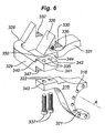
- Fig. 6 illustrates a third embodiment of the present invention, which is a further variant of the first embodiment and in which like numerals reference similar parts, but with the addition of the prefix "3", and only differences with respect to the first embodiment are discussed in great depth.
- the adapter plate 316 is provided with a first and second coplanar adapter plate surfaces 343 (only one shown in fig. 6 ) having a pair of tangential radial bores 322 provided therein, which bores extend substantially perpendicular to longitudinal axis A of the axle.
- the plane on which the surfaces lie is a chord of an imaginary circle whose centre is axis A.
- the reaction side carrier portion is provided with first and second complimentary carrier mating surfaces 341 (again, only one shown in fig. 6 ) and aligned bores 335.
- opposing surfaces 341 and parallel thereto are third and fourth carrier surfaces 340 configured to contact first and second surfaces 350 of the actuating side portion 326 of the carrier.
- Further threaded bores extend into the actuating side portion 326 such that all three components may be held together.
- the arms 329 of the reaction side carrier portion 328 are sandwiched between the adapter plate surfaces 343 and the actuating side portion 326 and are securely bolted together by bolts 337.
- the reaction side carrier portion is provided with a further abutment surface 347 extending transverse to the axis of the axle, and arranged to contact a corresponding surface of the adapter plate 316 (not visible).
- the actuating side carrier portion 326 is provided with a surface 344 extending parallel to the axis A of the axle and which is arranged to contact a corresponding surface 342 of the reaction side carrier portion 328.
- the order of the adapter plate 316 reaction side carrier portion 328 and actuating carrier portion 326 may be altered, so that, for example, the actuating side carrier portion 326 may be sandwiched between the adapter plate 316 and reaction side portion 328, or the adapter plate 316 may be sandwiched between the other two portions.
- the second embodiment of the present invention illustrated in fig. 5 may be adapted to provide for tangential bolting, rather than axial bolting, in which the reaction side portion 228 may be secured to the integral actuating side portion via tangential bolts and tangential mating surfaces.
- the arrangement may be altered such that the bolts are secured in a radially inward rather than radially outward direction, and the corresponding pairs of surfaces may be angled with respect to each other, rather than being coplanar.
- both portions may be cast, or both may be forged and the advantages of reduced material, part count, weight, and of ease of assembly are retained.
- manufacturing a carrier from two portions makes it technically feasible to forge both portions such that both portions may require no or minimal machining, and no or minimal induction hardening or the like.
- the provision of a two-portion carrier enables the reaction portion to be unbolted and removed with the caliper remaining in-situ on the guide pins.
- the geometry of the brake can be such that a normal one-piece brake rotor can be removed without removing the caliper. This is advantageous from a servicing point of view as it reduces maintenance time, and the problems associated with lifting a heavy caliper once it is removed.
- actuating portion may be provided in the actuating bridge, and the remainder of the actuating portion cast around the bar.
- the carrier may be adapted for any suitable fixing arrangement to an axle or steering knuckle, including, in the case of the first embodiment, direct welding to the axle.
- Alternative forms of mating faces for the actuating and reaction side portions may be employed.
Landscapes
- Engineering & Computer Science (AREA)
- General Engineering & Computer Science (AREA)
- Mechanical Engineering (AREA)
- Braking Arrangements (AREA)
- Valve Device For Special Equipments (AREA)
Claims (14)
- Flasque de frein (124, 224, 324) pour un frein à disque de véhicule lourd, le flasque comprenant :une portion de flasque pour le côté d'actionnement (126, 226, 326) comportant un support pour une plaquette de frein du côté d'actionnement comprenant un premier matériau ayant une première propriété ;une portion de flasque séparée pour le côté de réaction (128, 228, 328) comportant un support pour une plaquette de frein du côté de réaction pour la fixation à la portion de flasque pour le côté d'actionnement ;caractérisé en ce que la portion de flasque pour le côté de réaction comprend un deuxième matériau ayant une deuxième propriété, la deuxième propriété étant différente de la première propriété ; et en ce que le premier matériau est un matériau forgé et le deuxième matériau est un matériau coulé.
- Flasque de frein selon la revendication 1, dans lequel le premier matériau a une plus grande résistance que le deuxième matériau.
- Flasque de frein selon la revendication 1 ou 2, dans lequel le premier matériau a une plus grande robustesse que le deuxième matériau.
- Flasque de frein selon l'une quelconque des revendications précédentes, dans lequel le premier matériau a une surface plus lisse que le deuxième matériau.
- Flasque de frein selon l'une quelconque des revendications précédentes, dans lequel le premier matériau est de l'acier forgé.
- Flasque de frein selon l'une quelconque des revendications précédentes, dans lequel le deuxième matériau est du fer forgé.
- Flasque de frein selon l'une quelconque des revendications précédentes, dans lequel la portion pour le côté d'actionnement comporte un retrait (130, 230, 330) comportant des surfaces de butée pour le support circonférentiel de la plaquette de frein du côté d'actionnement, les surfaces de butée n'étant de préférence pas usinées.
- Flasque de frein selon la revendication 7, dans lequel les surfaces de butée ne sont pas durcies par induction.
- Flasque de frein selon l'une quelconque des revendications précédentes, dans lequel la portion de flasque pour le côté de réaction comprend en outre des bras (129, 229, 329) configurés pour s'étendre par-dessus un rotor de frein du frein, pendant l'utilisation.
- Flasque de frein selon l'une quelconque des revendications précédentes, dans lequel les portions de flasque pour les côtés d'actionnement et de réaction comportent des surfaces d'accouplement complémentaires, la ou les surfaces d'accouplement de la portion de flasque pour le côté d'actionnement n'étant de préférence pas usinées.
- Flasque de frein selon la revendication 10, dans lequel les surfaces d'accouplement comportent des surfaces d'accouplement circonférentielles complémentaires.
- Flasque de frein selon l'une quelconque des revendications précédentes, dans lequel la portion de flasque pour le côté d'actionnement comprend en outre une formation de montage intégrale pour monter la portion sur un essieu (10), une articulation de direction ou un composant de suspension, et dans lequel la formation de montage est de préférence une fixation pour un étrier de fixation de frein à tambour.
- Procédé de fabrication d'un flasque ayant une portion pour le côté d'actionnement (126, 226, 326) et une portion pour le côté de réaction séparée (128, 228, 328) comprenant les étapes consistant à :1) forger la portion pour le côté d'actionnement de manière à ce qu'elle comprenne un premier matériau ayant une première propriété ;2) couler la portion pour le côté de réaction de manière à ce qu'elle comprenne un deuxième matériau ayant une deuxième propriété différente de la première propriété,3) assembler la portion pour le côté d'actionnement et la portion pour le côté de réaction l'une à l'autre pour former un flasque complet.
- Frein à disque comportant un flasque de frein (124, 224, 324) selon l'une quelconque des revendications 1 à 12.
Applications Claiming Priority (1)
| Application Number | Priority Date | Filing Date | Title |
|---|---|---|---|
| GBGB0618416.2A GB0618416D0 (en) | 2006-09-19 | 2006-09-19 | A brake carrier |
Publications (3)
| Publication Number | Publication Date |
|---|---|
| EP1903242A2 EP1903242A2 (fr) | 2008-03-26 |
| EP1903242A3 EP1903242A3 (fr) | 2009-04-01 |
| EP1903242B1 true EP1903242B1 (fr) | 2011-03-23 |
Family
ID=37421230
Family Applications (1)
| Application Number | Title | Priority Date | Filing Date |
|---|---|---|---|
| EP07253670A Active EP1903242B1 (fr) | 2006-09-19 | 2007-09-17 | Flasque de frein |
Country Status (8)
| Country | Link |
|---|---|
| US (1) | US9222532B2 (fr) |
| EP (1) | EP1903242B1 (fr) |
| JP (1) | JP5207691B2 (fr) |
| CN (2) | CN102537147A (fr) |
| AT (1) | ATE503128T1 (fr) |
| BR (1) | BRPI0705957A2 (fr) |
| DE (1) | DE602007013331D1 (fr) |
| GB (1) | GB0618416D0 (fr) |
Cited By (2)
| Publication number | Priority date | Publication date | Assignee | Title |
|---|---|---|---|---|
| EP2895763B1 (fr) | 2012-09-17 | 2018-05-09 | KNORR-BREMSE Systeme für Nutzfahrzeuge GmbH | Support de frein |
| WO2023285237A1 (fr) * | 2021-07-13 | 2023-01-19 | Knorr-Bremse Systeme für Nutzfahrzeuge GmbH | Support de frein et frein à disque |
Families Citing this family (36)
| Publication number | Priority date | Publication date | Assignee | Title |
|---|---|---|---|---|
| DE202004013006U1 (de) * | 2004-07-15 | 2004-11-04 | Otto Sauer Achsenfabrik Keilberg | Bremseinrichtung mit Bremssattelbefestigung |
| DE102004050349B4 (de) * | 2004-10-15 | 2007-06-14 | Wabco Radbremsen Gmbh | Nutzfahrzeuge-Scheibenbremse |
| JP4999810B2 (ja) * | 2008-09-30 | 2012-08-15 | 日立オートモティブシステムズ株式会社 | ディスクブレーキ |
| US20120067678A1 (en) * | 2010-09-21 | 2012-03-22 | Kelsey-Hayes Company | Anchor bracket for use in a disc brake assembly and method for making the same |
| DE102011016928A1 (de) * | 2011-04-13 | 2012-10-18 | Lucas Automotive Gmbh | Verfahren zum Herstellen eines Bremsträgers für eine Scheibenbremse und Bremsträger für eine Scheibenbremse |
| CN102221056B (zh) * | 2011-07-01 | 2016-01-13 | 奇瑞汽车股份有限公司 | 一种制动钳支架 |
| KR101317666B1 (ko) * | 2012-03-16 | 2013-10-18 | 주식회사 세림티앤디 | 고압출 정밀 단조를 이용한 자동차의 전자동 주차 브레이크용 캐리어 제조방법 및 장치 |
| DE102012006110B4 (de) * | 2012-03-26 | 2015-04-30 | Knorr-Bremse Systeme für Nutzfahrzeuge GmbH | Bremsträger für eine Schiebesattel-Scheibenbremse |
| TR201209143A2 (fr) | 2012-08-06 | 2013-08-22 | Ege Fren Sanayi̇ Ve Ti̇caret Anoni̇m Şi̇rketi̇ | |
| US8973720B2 (en) | 2012-08-17 | 2015-03-10 | Bendix Spicer Foundation Brake Llc | Disc brake pad mounting and retention system and method |
| US8973240B2 (en) | 2012-08-17 | 2015-03-10 | Bendix Spicer Foundation Brake Llc | Disc brake pad mounting and retention system and method |
| US8544614B1 (en) | 2012-08-17 | 2013-10-01 | Bendix Spicer Foundation Brake Llc | Disc brake pad mounting and retention system and method |
| US8960381B2 (en) | 2012-08-17 | 2015-02-24 | Bendix Spicer Foundation Brake Llc | Disc brake pad mounting and retention system and method |
| US8540061B1 (en) | 2012-08-17 | 2013-09-24 | Bendix Spicer Foundation Brake Llc | Disc brake pad mounting and retention system and method |
| US9353810B2 (en) * | 2013-02-21 | 2016-05-31 | Kelsey-Hayes Company | Disc brake assembly with non-rotatable vehicle component and method for producing same |
| DE102013016312A1 (de) | 2013-10-04 | 2015-04-09 | Knorr-Bremse Systeme für Nutzfahrzeuge GmbH | Scheibenbremse |
| AU2015276964B2 (en) * | 2014-06-20 | 2018-02-08 | Hendrickson Usa, L.L.C. | Reduced-diameter brake rotor for heavy-duty vehicles |
| USD822563S1 (en) * | 2014-07-17 | 2018-07-10 | Dennis Michael Nosworthy | Disc brake caliper bracket |
| CA2957982C (fr) * | 2014-09-16 | 2019-01-15 | Hendrickson Usa, L.L.C. | Plaque de couple amelioree pour vehicule lourd |
| US10247266B2 (en) | 2014-10-30 | 2019-04-02 | Bwi (Shanghai) Co., Ltd. | Brake mounting bracket apparatus |
| EP3051170B1 (fr) * | 2015-01-28 | 2019-10-23 | Meritor Heavy Vehicle Braking Systems (UK) Limited | Frein à disque |
| US9726243B2 (en) * | 2015-03-20 | 2017-08-08 | Bendix Spicer Foundation Brake Llc | Disc brake pad retention system and mounting method |
| CN104776134A (zh) * | 2015-03-27 | 2015-07-15 | 江苏佰瑞克汽配有限公司 | 一种汽车碟刹支架 |
| USD771540S1 (en) * | 2015-06-15 | 2016-11-15 | Saf-Holland, Inc. | Brake spider |
| EP3121477B1 (fr) * | 2015-07-21 | 2022-10-05 | Meritor Heavy Vehicle Braking Systems (UK) Limited | Ensemble de disque de frein |
| DE102017105641B4 (de) * | 2017-03-16 | 2022-09-15 | Knorr-Bremse Systeme für Nutzfahrzeuge GmbH | Bremsträger und Scheibenbremse |
| EP3333442B1 (fr) * | 2016-12-06 | 2020-05-20 | Meritor Heavy Vehicle Braking Systems (UK) Limited | Fixation pour un support de frein et support pour un frein à disque et procédé associé |
| WO2018157084A1 (fr) | 2017-02-26 | 2018-08-30 | LIFI Labs, Inc. | Système d'éclairage |
| DE102017110641A1 (de) * | 2017-05-16 | 2018-11-22 | Knorr-Bremse Systeme für Nutzfahrzeuge GmbH | Bremsenbauteil einer Scheibenbremse und Anordnung mit einer Scheibenbremse |
| CN107420464A (zh) * | 2017-09-30 | 2017-12-01 | 山西中晋工业机械有限公司 | 一种汽车制动盘用的连接板加工工艺 |
| US10400837B2 (en) | 2017-10-11 | 2019-09-03 | Arvinmeritor Technology, Llc | Brake carrier and method of manufacture |
| DE102017011338A1 (de) * | 2017-12-08 | 2019-06-13 | Wabco Europe Bvba | Bremsträger für eine Scheibenbremse |
| EP3546784A1 (fr) * | 2018-03-28 | 2019-10-02 | Meritor Heavy Vehicle Braking Systems (UK) Limited | Assemblage de frein |
| US10948035B2 (en) * | 2018-11-29 | 2021-03-16 | Advics Co., Ltd. | Brake half-caliper and method of making brake half-caliper |
| US10900529B2 (en) * | 2019-01-17 | 2021-01-26 | Emilio Cervantes | Brake caliper mounting assembly |
| US20230272829A1 (en) * | 2022-02-25 | 2023-08-31 | Bendix Commercial Vehicle Systems Llc | Friction Pad Carrier for a Disc Brake |
Family Cites Families (25)
| Publication number | Priority date | Publication date | Assignee | Title |
|---|---|---|---|---|
| US3093890A (en) * | 1958-03-04 | 1963-06-18 | Sparks Cleone Arthur | Method for impact-forming slipper-type pistons |
| US3371756A (en) * | 1966-01-18 | 1968-03-05 | Albert W. Spitz | Heat dissipating brake |
| GB1262263A (en) * | 1968-04-05 | 1972-02-02 | Girling Ltd | Improvements in or relating to vehicle disc brakes |
| US3630487A (en) * | 1970-02-16 | 1971-12-28 | Lester E Wechter Jr | Wheel-raising device |
| FR2321351A1 (fr) * | 1975-07-30 | 1977-03-18 | Quichaud Daniel | Procedes de fabrication d'axes, de vis, de boulons, et de pieces metalliques analogues, et les pieces ainsi obtenues |
| GB1574131A (en) * | 1976-02-18 | 1980-09-03 | Girling Ltd | Sliding caliper disc brake |
| GB2027826B (en) | 1978-06-29 | 1982-07-28 | Lucas Industries Ltd | Disc brake assembly |
| US4256445A (en) * | 1978-10-12 | 1981-03-17 | Pingree Robert J | Trowel means for lining and smoothing the interior of pipes with a protective coating |
| DE3245157A1 (de) | 1982-12-07 | 1984-06-07 | Alfred Teves Gmbh, 6000 Frankfurt | Bremssattelgehaeuse, insbesondere fuer eine teilbelag-scheibenbremse eines kraftfahrzeuges und verfahren zur herstellung des gehaeuses |
| DE4036272A1 (de) * | 1990-11-14 | 1992-05-21 | Perrot Bremse Gmbh Deutsche | Gleitsattel-scheibenbremse |
| US5538105A (en) * | 1995-03-07 | 1996-07-23 | Dayton Walther Corporation | Brake shoe hold down clip for disc brake assembly |
| DE19823034C1 (de) * | 1998-05-22 | 1999-12-02 | Wabco Perrot Bremsen Gmbh | Scheibenbremse für ein Landfahrzeug |
| JP3428445B2 (ja) * | 1998-07-06 | 2003-07-22 | 住友電気工業株式会社 | ラジアルマウント型ディスクブレーキ |
| DE19855275B4 (de) * | 1998-12-01 | 2004-02-19 | Daimlerchrysler Ag | Teilbelagscheibenbremse in Form einer Festsattelbremse |
| DE19857074B4 (de) * | 1998-12-10 | 2009-08-06 | Knorr-Bremse Systeme für Nutzfahrzeuge GmbH | Pneumatische Scheibenbremse und Bremsträger |
| US6302243B1 (en) * | 1999-10-29 | 2001-10-16 | Stoptech Technologies Llc | Stiffening bracket for brake calipers |
| US20030042082A1 (en) | 2001-08-29 | 2003-03-06 | Mccann Denis John | Vehicle axle assembly having a brake carrier secured directly to the axle |
| US6820884B2 (en) * | 2001-08-29 | 2004-11-23 | Meritor Heavy Vehicle Braking Systems | Integrated axle adaptor and spring seat for a vehicle suspension system |
| GB0214705D0 (en) * | 2002-06-26 | 2002-08-07 | Meritor Heavy Vehicle Braking | Pad spring and disc brake incorporating a pad spring |
| JP4076818B2 (ja) * | 2002-08-12 | 2008-04-16 | Ntn株式会社 | 等速自在継手 |
| EP1494917B1 (fr) * | 2003-02-28 | 2006-03-22 | Freni Brembo S.p.A. | Etrier de frein a disque et element de support d'etrier |
| DE10312478B4 (de) * | 2003-03-20 | 2007-03-29 | Lucas Automotive Gmbh | Scheibenbremse |
| JP4476576B2 (ja) * | 2003-08-27 | 2010-06-09 | 本田技研工業株式会社 | パーキングブレーキ構造 |
| DE202004013006U1 (de) * | 2004-07-15 | 2004-11-04 | Otto Sauer Achsenfabrik Keilberg | Bremseinrichtung mit Bremssattelbefestigung |
| JP2006057718A (ja) | 2004-08-19 | 2006-03-02 | Akebono Brake Ind Co Ltd | フローティングキャリパ型ディスクブレーキ |
-
2006
- 2006-09-19 GB GBGB0618416.2A patent/GB0618416D0/en not_active Ceased
-
2007
- 2007-09-12 JP JP2007236124A patent/JP5207691B2/ja not_active Expired - Fee Related
- 2007-09-17 AT AT07253670T patent/ATE503128T1/de not_active IP Right Cessation
- 2007-09-17 EP EP07253670A patent/EP1903242B1/fr active Active
- 2007-09-17 DE DE602007013331T patent/DE602007013331D1/de active Active
- 2007-09-18 US US11/856,980 patent/US9222532B2/en not_active Expired - Fee Related
- 2007-09-18 BR BRPI0705957-4A patent/BRPI0705957A2/pt not_active Application Discontinuation
- 2007-09-19 CN CN2012100288683A patent/CN102537147A/zh active Pending
- 2007-09-19 CN CN2007101541692A patent/CN101149086B/zh not_active Expired - Fee Related
Cited By (2)
| Publication number | Priority date | Publication date | Assignee | Title |
|---|---|---|---|---|
| EP2895763B1 (fr) | 2012-09-17 | 2018-05-09 | KNORR-BREMSE Systeme für Nutzfahrzeuge GmbH | Support de frein |
| WO2023285237A1 (fr) * | 2021-07-13 | 2023-01-19 | Knorr-Bremse Systeme für Nutzfahrzeuge GmbH | Support de frein et frein à disque |
Also Published As
| Publication number | Publication date |
|---|---|
| CN101149086A (zh) | 2008-03-26 |
| GB0618416D0 (en) | 2006-11-01 |
| JP5207691B2 (ja) | 2013-06-12 |
| DE602007013331D1 (de) | 2011-05-05 |
| EP1903242A3 (fr) | 2009-04-01 |
| ATE503128T1 (de) | 2011-04-15 |
| US9222532B2 (en) | 2015-12-29 |
| CN102537147A (zh) | 2012-07-04 |
| CN101149086B (zh) | 2012-03-21 |
| EP1903242A2 (fr) | 2008-03-26 |
| BRPI0705957A2 (pt) | 2008-11-11 |
| US20080067015A1 (en) | 2008-03-20 |
| JP2008075874A (ja) | 2008-04-03 |
Similar Documents
| Publication | Publication Date | Title |
|---|---|---|
| EP1903242B1 (fr) | Flasque de frein | |
| EP1276655B1 (fr) | Rotule de direction | |
| JP4149515B2 (ja) | ディスクブレーキ用ディスク―ハブ接続装置 | |
| US8307958B2 (en) | Brake support plate | |
| EP1801447B1 (fr) | Ensemble d'étrier de frein | |
| EP1303708B1 (fr) | Corps d'etrier pour un frein a disque a etrier fixe | |
| EP1831579B1 (fr) | Systeme de frein a disque | |
| EP1650462A1 (fr) | Rotor de frein à disque | |
| GB2451690A (en) | Disk brake caliper having a peripheral stiffening band | |
| EP1151208B1 (fr) | Support de moyeu | |
| EP0067113B1 (fr) | Structure d'un ensemble de tube-moyeu pour frein à disques à clavettes et bague-support remplaçables | |
| US4509619A (en) | Shoe mounted disc brake caliper and shoe support structure | |
| US6719104B1 (en) | Composite caliper for a disc brake assembly and method for producing same | |
| EP1806516B1 (fr) | Frein multidisques | |
| US4342380A (en) | Light weight disc brake caliper | |
| US20060289251A1 (en) | Taper wear compensation of a friction pad for a disc brake assembly | |
| US20090145702A1 (en) | Brake pad for a vehicle disc brake assembly | |
| US6598716B1 (en) | Rotor for a vehicle brake assembly and method for producing same | |
| US20160356329A1 (en) | Integrated torque plate and brake carrier | |
| CA2386134A1 (fr) | Frein de camion de chantier et fusee de roue comprenant un joint cannele | |
| GB2104985A (en) | Disc brakes | |
| WO1999013239A1 (fr) | Ensemble frein pour vehicule routier | |
| WO2005064189A1 (fr) | Etrier modulaire a monture flexible | |
| CA1168995A (fr) | Boulon de calage pour garniture de frein a disque | |
| GB2413162A (en) | Brake carrier |
Legal Events
| Date | Code | Title | Description |
|---|---|---|---|
| PUAI | Public reference made under article 153(3) epc to a published international application that has entered the european phase |
Free format text: ORIGINAL CODE: 0009012 |
|
| AK | Designated contracting states |
Kind code of ref document: A2 Designated state(s): AT BE BG CH CY CZ DE DK EE ES FI FR GB GR HU IE IS IT LI LT LU LV MC MT NL PL PT RO SE SI SK TR |
|
| AX | Request for extension of the european patent |
Extension state: AL BA HR MK YU |
|
| PUAL | Search report despatched |
Free format text: ORIGINAL CODE: 0009013 |
|
| AK | Designated contracting states |
Kind code of ref document: A3 Designated state(s): AT BE BG CH CY CZ DE DK EE ES FI FR GB GR HU IE IS IT LI LT LU LV MC MT NL PL PT RO SE SI SK TR |
|
| AX | Request for extension of the european patent |
Extension state: AL BA HR MK RS |
|
| 17P | Request for examination filed |
Effective date: 20090904 |
|
| 17Q | First examination report despatched |
Effective date: 20091006 |
|
| AKX | Designation fees paid |
Designated state(s): AT BE BG CH CY CZ DE DK EE ES FI FR GB GR HU IE IS IT LI LT LU LV MC MT NL PL PT RO SE SI SK TR |
|
| GRAP | Despatch of communication of intention to grant a patent |
Free format text: ORIGINAL CODE: EPIDOSNIGR1 |
|
| GRAS | Grant fee paid |
Free format text: ORIGINAL CODE: EPIDOSNIGR3 |
|
| GRAA | (expected) grant |
Free format text: ORIGINAL CODE: 0009210 |
|
| AK | Designated contracting states |
Kind code of ref document: B1 Designated state(s): AT BE BG CH CY CZ DE DK EE ES FI FR GB GR HU IE IS IT LI LT LU LV MC MT NL PL PT RO SE SI SK TR |
|
| REG | Reference to a national code |
Ref country code: GB Ref legal event code: FG4D |
|
| REG | Reference to a national code |
Ref country code: CH Ref legal event code: EP |
|
| REG | Reference to a national code |
Ref country code: IE Ref legal event code: FG4D |
|
| REF | Corresponds to: |
Ref document number: 602007013331 Country of ref document: DE Date of ref document: 20110505 Kind code of ref document: P |
|
| REG | Reference to a national code |
Ref country code: DE Ref legal event code: R096 Ref document number: 602007013331 Country of ref document: DE Effective date: 20110505 |
|
| REG | Reference to a national code |
Ref country code: SE Ref legal event code: TRGR |
|
| REG | Reference to a national code |
Ref country code: NL Ref legal event code: VDEP Effective date: 20110323 |
|
| PG25 | Lapsed in a contracting state [announced via postgrant information from national office to epo] |
Ref country code: GR Free format text: LAPSE BECAUSE OF FAILURE TO SUBMIT A TRANSLATION OF THE DESCRIPTION OR TO PAY THE FEE WITHIN THE PRESCRIBED TIME-LIMIT Effective date: 20110624 Ref country code: LV Free format text: LAPSE BECAUSE OF FAILURE TO SUBMIT A TRANSLATION OF THE DESCRIPTION OR TO PAY THE FEE WITHIN THE PRESCRIBED TIME-LIMIT Effective date: 20110323 Ref country code: LT Free format text: LAPSE BECAUSE OF FAILURE TO SUBMIT A TRANSLATION OF THE DESCRIPTION OR TO PAY THE FEE WITHIN THE PRESCRIBED TIME-LIMIT Effective date: 20110323 |
|
| LTIE | Lt: invalidation of european patent or patent extension |
Effective date: 20110323 |
|
| PG25 | Lapsed in a contracting state [announced via postgrant information from national office to epo] |
Ref country code: BG Free format text: LAPSE BECAUSE OF FAILURE TO SUBMIT A TRANSLATION OF THE DESCRIPTION OR TO PAY THE FEE WITHIN THE PRESCRIBED TIME-LIMIT Effective date: 20110623 Ref country code: CY Free format text: LAPSE BECAUSE OF FAILURE TO SUBMIT A TRANSLATION OF THE DESCRIPTION OR TO PAY THE FEE WITHIN THE PRESCRIBED TIME-LIMIT Effective date: 20110323 Ref country code: FI Free format text: LAPSE BECAUSE OF FAILURE TO SUBMIT A TRANSLATION OF THE DESCRIPTION OR TO PAY THE FEE WITHIN THE PRESCRIBED TIME-LIMIT Effective date: 20110323 Ref country code: AT Free format text: LAPSE BECAUSE OF FAILURE TO SUBMIT A TRANSLATION OF THE DESCRIPTION OR TO PAY THE FEE WITHIN THE PRESCRIBED TIME-LIMIT Effective date: 20110323 Ref country code: SI Free format text: LAPSE BECAUSE OF FAILURE TO SUBMIT A TRANSLATION OF THE DESCRIPTION OR TO PAY THE FEE WITHIN THE PRESCRIBED TIME-LIMIT Effective date: 20110323 |
|
| PG25 | Lapsed in a contracting state [announced via postgrant information from national office to epo] |
Ref country code: BE Free format text: LAPSE BECAUSE OF FAILURE TO SUBMIT A TRANSLATION OF THE DESCRIPTION OR TO PAY THE FEE WITHIN THE PRESCRIBED TIME-LIMIT Effective date: 20110323 |
|
| PG25 | Lapsed in a contracting state [announced via postgrant information from national office to epo] |
Ref country code: EE Free format text: LAPSE BECAUSE OF FAILURE TO SUBMIT A TRANSLATION OF THE DESCRIPTION OR TO PAY THE FEE WITHIN THE PRESCRIBED TIME-LIMIT Effective date: 20110323 Ref country code: PT Free format text: LAPSE BECAUSE OF FAILURE TO SUBMIT A TRANSLATION OF THE DESCRIPTION OR TO PAY THE FEE WITHIN THE PRESCRIBED TIME-LIMIT Effective date: 20110725 |
|
| PG25 | Lapsed in a contracting state [announced via postgrant information from national office to epo] |
Ref country code: IS Free format text: LAPSE BECAUSE OF FAILURE TO SUBMIT A TRANSLATION OF THE DESCRIPTION OR TO PAY THE FEE WITHIN THE PRESCRIBED TIME-LIMIT Effective date: 20110723 Ref country code: ES Free format text: LAPSE BECAUSE OF FAILURE TO SUBMIT A TRANSLATION OF THE DESCRIPTION OR TO PAY THE FEE WITHIN THE PRESCRIBED TIME-LIMIT Effective date: 20110704 Ref country code: SK Free format text: LAPSE BECAUSE OF FAILURE TO SUBMIT A TRANSLATION OF THE DESCRIPTION OR TO PAY THE FEE WITHIN THE PRESCRIBED TIME-LIMIT Effective date: 20110323 Ref country code: RO Free format text: LAPSE BECAUSE OF FAILURE TO SUBMIT A TRANSLATION OF THE DESCRIPTION OR TO PAY THE FEE WITHIN THE PRESCRIBED TIME-LIMIT Effective date: 20110323 |
|
| PG25 | Lapsed in a contracting state [announced via postgrant information from national office to epo] |
Ref country code: NL Free format text: LAPSE BECAUSE OF FAILURE TO SUBMIT A TRANSLATION OF THE DESCRIPTION OR TO PAY THE FEE WITHIN THE PRESCRIBED TIME-LIMIT Effective date: 20110323 |
|
| PLBI | Opposition filed |
Free format text: ORIGINAL CODE: 0009260 |
|
| PLAB | Opposition data, opponent's data or that of the opponent's representative modified |
Free format text: ORIGINAL CODE: 0009299OPPO |
|
| 26 | Opposition filed |
Opponent name: KNORR-BREMSE SYSTEME FUER NUTZFAHRZEUGE GMBH Effective date: 20111222 |
|
| PLAX | Notice of opposition and request to file observation + time limit sent |
Free format text: ORIGINAL CODE: EPIDOSNOBS2 |
|
| PLAF | Information modified related to communication of a notice of opposition and request to file observations + time limit |
Free format text: ORIGINAL CODE: EPIDOSCOBS2 |
|
| R26 | Opposition filed (corrected) |
Opponent name: KNORR-BREMSE SYSTEME FUER NUTZFAHRZEUGE GMBH Effective date: 20111222 |
|
| PG25 | Lapsed in a contracting state [announced via postgrant information from national office to epo] |
Ref country code: PL Free format text: LAPSE BECAUSE OF FAILURE TO SUBMIT A TRANSLATION OF THE DESCRIPTION OR TO PAY THE FEE WITHIN THE PRESCRIBED TIME-LIMIT Effective date: 20110323 |
|
| REG | Reference to a national code |
Ref country code: DE Ref legal event code: R026 Ref document number: 602007013331 Country of ref document: DE Effective date: 20111222 |
|
| PG25 | Lapsed in a contracting state [announced via postgrant information from national office to epo] |
Ref country code: MC Free format text: LAPSE BECAUSE OF NON-PAYMENT OF DUE FEES Effective date: 20110930 Ref country code: CZ Free format text: LAPSE BECAUSE OF NON-PAYMENT OF DUE FEES Effective date: 20110917 |
|
| REG | Reference to a national code |
Ref country code: CH Ref legal event code: PL |
|
| PLAF | Information modified related to communication of a notice of opposition and request to file observations + time limit |
Free format text: ORIGINAL CODE: EPIDOSCOBS2 |
|
| PG25 | Lapsed in a contracting state [announced via postgrant information from national office to epo] |
Ref country code: IT Free format text: LAPSE BECAUSE OF FAILURE TO SUBMIT A TRANSLATION OF THE DESCRIPTION OR TO PAY THE FEE WITHIN THE PRESCRIBED TIME-LIMIT Effective date: 20110323 |
|
| REG | Reference to a national code |
Ref country code: IE Ref legal event code: MM4A |
|
| REG | Reference to a national code |
Ref country code: FR Ref legal event code: ST Effective date: 20120531 |
|
| PG25 | Lapsed in a contracting state [announced via postgrant information from national office to epo] |
Ref country code: LI Free format text: LAPSE BECAUSE OF NON-PAYMENT OF DUE FEES Effective date: 20110930 Ref country code: CH Free format text: LAPSE BECAUSE OF NON-PAYMENT OF DUE FEES Effective date: 20110930 Ref country code: IE Free format text: LAPSE BECAUSE OF NON-PAYMENT OF DUE FEES Effective date: 20110917 |
|
| PLBB | Reply of patent proprietor to notice(s) of opposition received |
Free format text: ORIGINAL CODE: EPIDOSNOBS3 |
|
| PG25 | Lapsed in a contracting state [announced via postgrant information from national office to epo] |
Ref country code: FR Free format text: LAPSE BECAUSE OF NON-PAYMENT OF DUE FEES Effective date: 20110930 |
|
| PG25 | Lapsed in a contracting state [announced via postgrant information from national office to epo] |
Ref country code: MT Free format text: LAPSE BECAUSE OF FAILURE TO SUBMIT A TRANSLATION OF THE DESCRIPTION OR TO PAY THE FEE WITHIN THE PRESCRIBED TIME-LIMIT Effective date: 20110323 |
|
| PLBP | Opposition withdrawn |
Free format text: ORIGINAL CODE: 0009264 |
|
| PLBD | Termination of opposition procedure: decision despatched |
Free format text: ORIGINAL CODE: EPIDOSNOPC1 |
|
| PG25 | Lapsed in a contracting state [announced via postgrant information from national office to epo] |
Ref country code: LU Free format text: LAPSE BECAUSE OF NON-PAYMENT OF DUE FEES Effective date: 20110917 |
|
| PLBM | Termination of opposition procedure: date of legal effect published |
Free format text: ORIGINAL CODE: 0009276 |
|
| STAA | Information on the status of an ep patent application or granted ep patent |
Free format text: STATUS: OPPOSITION PROCEDURE CLOSED |
|
| PG25 | Lapsed in a contracting state [announced via postgrant information from national office to epo] |
Ref country code: TR Free format text: LAPSE BECAUSE OF FAILURE TO SUBMIT A TRANSLATION OF THE DESCRIPTION OR TO PAY THE FEE WITHIN THE PRESCRIBED TIME-LIMIT Effective date: 20110323 |
|
| 27C | Opposition proceedings terminated |
Effective date: 20130526 |
|
| PG25 | Lapsed in a contracting state [announced via postgrant information from national office to epo] |
Ref country code: HU Free format text: LAPSE BECAUSE OF FAILURE TO SUBMIT A TRANSLATION OF THE DESCRIPTION OR TO PAY THE FEE WITHIN THE PRESCRIBED TIME-LIMIT Effective date: 20110323 |
|
| PGFP | Annual fee paid to national office [announced via postgrant information from national office to epo] |
Ref country code: GB Payment date: 20150928 Year of fee payment: 9 |
|
| GBPC | Gb: european patent ceased through non-payment of renewal fee |
Effective date: 20160917 |
|
| PG25 | Lapsed in a contracting state [announced via postgrant information from national office to epo] |
Ref country code: GB Free format text: LAPSE BECAUSE OF NON-PAYMENT OF DUE FEES Effective date: 20160917 |
|
| P01 | Opt-out of the competence of the unified patent court (upc) registered |
Effective date: 20230531 |
|
| PGFP | Annual fee paid to national office [announced via postgrant information from national office to epo] |
Ref country code: SE Payment date: 20230927 Year of fee payment: 17 Ref country code: DE Payment date: 20230927 Year of fee payment: 17 |