EP1902483B1 - Systeme d interconnexion pour un ensemble de stockage d energie - Google Patents
Systeme d interconnexion pour un ensemble de stockage d energie Download PDFInfo
- Publication number
- EP1902483B1 EP1902483B1 EP06778759.8A EP06778759A EP1902483B1 EP 1902483 B1 EP1902483 B1 EP 1902483B1 EP 06778759 A EP06778759 A EP 06778759A EP 1902483 B1 EP1902483 B1 EP 1902483B1
- Authority
- EP
- European Patent Office
- Prior art keywords
- cell
- energy storage
- circuit
- cells
- interconnecting
- Prior art date
- Legal status (The legal status is an assumption and is not a legal conclusion. Google has not performed a legal analysis and makes no representation as to the accuracy of the status listed.)
- Not-in-force
Links
- 238000004146 energy storage Methods 0.000 title claims description 93
- 210000004027 cell Anatomy 0.000 claims description 108
- 210000000352 storage cell Anatomy 0.000 claims description 63
- 230000004913 activation Effects 0.000 claims description 18
- 230000009849 deactivation Effects 0.000 claims description 16
- 238000000034 method Methods 0.000 claims description 13
- 239000000758 substrate Substances 0.000 claims description 5
- WHXSMMKQMYFTQS-UHFFFAOYSA-N Lithium Chemical compound [Li] WHXSMMKQMYFTQS-UHFFFAOYSA-N 0.000 claims description 3
- 229910052782 aluminium Inorganic materials 0.000 claims description 3
- XAGFODPZIPBFFR-UHFFFAOYSA-N aluminium Chemical compound [Al] XAGFODPZIPBFFR-UHFFFAOYSA-N 0.000 claims description 3
- 229910052744 lithium Inorganic materials 0.000 claims description 3
- 229920000642 polymer Polymers 0.000 claims description 3
- 230000017525 heat dissipation Effects 0.000 claims description 2
- 229910001416 lithium ion Inorganic materials 0.000 claims description 2
- 229910052751 metal Inorganic materials 0.000 claims description 2
- 239000002184 metal Substances 0.000 claims description 2
- 239000004411 aluminium Substances 0.000 claims 2
- 229920000728 polyester Polymers 0.000 claims 2
- 230000001681 protective effect Effects 0.000 claims 2
- 238000005259 measurement Methods 0.000 description 18
- 230000021715 photosynthesis, light harvesting Effects 0.000 description 10
- 239000004020 conductor Substances 0.000 description 8
- 238000005516 engineering process Methods 0.000 description 6
- 230000036541 health Effects 0.000 description 6
- 238000007639 printing Methods 0.000 description 6
- 230000000712 assembly Effects 0.000 description 5
- 238000000429 assembly Methods 0.000 description 5
- 230000002950 deficient Effects 0.000 description 4
- 238000010438 heat treatment Methods 0.000 description 4
- 238000010586 diagram Methods 0.000 description 3
- RYGMFSIKBFXOCR-UHFFFAOYSA-N Copper Chemical compound [Cu] RYGMFSIKBFXOCR-UHFFFAOYSA-N 0.000 description 2
- PXHVJJICTQNCMI-UHFFFAOYSA-N Nickel Chemical compound [Ni] PXHVJJICTQNCMI-UHFFFAOYSA-N 0.000 description 2
- 230000008901 benefit Effects 0.000 description 2
- 230000033228 biological regulation Effects 0.000 description 2
- 230000006835 compression Effects 0.000 description 2
- 238000007906 compression Methods 0.000 description 2
- 238000001514 detection method Methods 0.000 description 2
- 238000004519 manufacturing process Methods 0.000 description 2
- HBBGRARXTFLTSG-UHFFFAOYSA-N Lithium ion Chemical compound [Li+] HBBGRARXTFLTSG-UHFFFAOYSA-N 0.000 description 1
- 101100007538 Neurospora crassa (strain ATCC 24698 / 74-OR23-1A / CBS 708.71 / DSM 1257 / FGSC 987) cpc-1 gene Proteins 0.000 description 1
- 238000004026 adhesive bonding Methods 0.000 description 1
- 238000012550 audit Methods 0.000 description 1
- 230000015572 biosynthetic process Effects 0.000 description 1
- 238000005219 brazing Methods 0.000 description 1
- 230000001413 cellular effect Effects 0.000 description 1
- 230000000295 complement effect Effects 0.000 description 1
- 239000000470 constituent Substances 0.000 description 1
- 238000010276 construction Methods 0.000 description 1
- 229910052802 copper Inorganic materials 0.000 description 1
- 239000010949 copper Substances 0.000 description 1
- 239000011889 copper foil Substances 0.000 description 1
- 230000008878 coupling Effects 0.000 description 1
- 238000010168 coupling process Methods 0.000 description 1
- 238000005859 coupling reaction Methods 0.000 description 1
- 230000007423 decrease Effects 0.000 description 1
- 230000003247 decreasing effect Effects 0.000 description 1
- 238000009795 derivation Methods 0.000 description 1
- 230000003292 diminished effect Effects 0.000 description 1
- 238000007599 discharging Methods 0.000 description 1
- 238000009826 distribution Methods 0.000 description 1
- 239000013013 elastic material Substances 0.000 description 1
- 230000003862 health status Effects 0.000 description 1
- 230000010354 integration Effects 0.000 description 1
- 239000000463 material Substances 0.000 description 1
- 229910052759 nickel Inorganic materials 0.000 description 1
- 238000010248 power generation Methods 0.000 description 1
- 230000004044 response Effects 0.000 description 1
- 238000003860 storage Methods 0.000 description 1
- 238000003466 welding Methods 0.000 description 1
Images


Classifications
-
- H—ELECTRICITY
- H01—ELECTRIC ELEMENTS
- H01M—PROCESSES OR MEANS, e.g. BATTERIES, FOR THE DIRECT CONVERSION OF CHEMICAL ENERGY INTO ELECTRICAL ENERGY
- H01M50/00—Constructional details or processes of manufacture of the non-active parts of electrochemical cells other than fuel cells, e.g. hybrid cells
- H01M50/50—Current conducting connections for cells or batteries
- H01M50/502—Interconnectors for connecting terminals of adjacent batteries; Interconnectors for connecting cells outside a battery casing
- H01M50/509—Interconnectors for connecting terminals of adjacent batteries; Interconnectors for connecting cells outside a battery casing characterised by the type of connection, e.g. mixed connections
- H01M50/51—Connection only in series
-
- H—ELECTRICITY
- H01—ELECTRIC ELEMENTS
- H01M—PROCESSES OR MEANS, e.g. BATTERIES, FOR THE DIRECT CONVERSION OF CHEMICAL ENERGY INTO ELECTRICAL ENERGY
- H01M50/00—Constructional details or processes of manufacture of the non-active parts of electrochemical cells other than fuel cells, e.g. hybrid cells
- H01M50/50—Current conducting connections for cells or batteries
- H01M50/502—Interconnectors for connecting terminals of adjacent batteries; Interconnectors for connecting cells outside a battery casing
- H01M50/505—Interconnectors for connecting terminals of adjacent batteries; Interconnectors for connecting cells outside a battery casing comprising a single busbar
-
- H—ELECTRICITY
- H01—ELECTRIC ELEMENTS
- H01M—PROCESSES OR MEANS, e.g. BATTERIES, FOR THE DIRECT CONVERSION OF CHEMICAL ENERGY INTO ELECTRICAL ENERGY
- H01M50/00—Constructional details or processes of manufacture of the non-active parts of electrochemical cells other than fuel cells, e.g. hybrid cells
- H01M50/50—Current conducting connections for cells or batteries
- H01M50/502—Interconnectors for connecting terminals of adjacent batteries; Interconnectors for connecting cells outside a battery casing
- H01M50/521—Interconnectors for connecting terminals of adjacent batteries; Interconnectors for connecting cells outside a battery casing characterised by the material
- H01M50/522—Inorganic material
-
- Y—GENERAL TAGGING OF NEW TECHNOLOGICAL DEVELOPMENTS; GENERAL TAGGING OF CROSS-SECTIONAL TECHNOLOGIES SPANNING OVER SEVERAL SECTIONS OF THE IPC; TECHNICAL SUBJECTS COVERED BY FORMER USPC CROSS-REFERENCE ART COLLECTIONS [XRACs] AND DIGESTS
- Y02—TECHNOLOGIES OR APPLICATIONS FOR MITIGATION OR ADAPTATION AGAINST CLIMATE CHANGE
- Y02E—REDUCTION OF GREENHOUSE GAS [GHG] EMISSIONS, RELATED TO ENERGY GENERATION, TRANSMISSION OR DISTRIBUTION
- Y02E60/00—Enabling technologies; Technologies with a potential or indirect contribution to GHG emissions mitigation
- Y02E60/10—Energy storage using batteries
-
- Y—GENERAL TAGGING OF NEW TECHNOLOGICAL DEVELOPMENTS; GENERAL TAGGING OF CROSS-SECTIONAL TECHNOLOGIES SPANNING OVER SEVERAL SECTIONS OF THE IPC; TECHNICAL SUBJECTS COVERED BY FORMER USPC CROSS-REFERENCE ART COLLECTIONS [XRACs] AND DIGESTS
- Y10—TECHNICAL SUBJECTS COVERED BY FORMER USPC
- Y10T—TECHNICAL SUBJECTS COVERED BY FORMER US CLASSIFICATION
- Y10T29/00—Metal working
- Y10T29/49—Method of mechanical manufacture
- Y10T29/49002—Electrical device making
- Y10T29/49108—Electric battery cell making
- Y10T29/49115—Electric battery cell making including coating or impregnating
Definitions
- the field of the invention relates to the technologies of energy storage assemblies. More specifically, the present invention relates to a system and a method for interconnecting an energy storage assembly with an electronic support for controlling its state of health.
- the invention also relates to an energy storage assembly provided with such an interconnection system.
- Overvoltage or overload are examples of phenomena caused by the presence of a defective cell. They degrade performance and reduce the life of the energy storage assembly.
- a programmable electronic support is integrated into the construction to control and protect energy storage cells from these phenomena.
- This support acquires, on the one hand, various characteristics of the state of health of the cells via a measurement circuit wired to the polar terminals of each energy storage cell of the assembly.
- the cable assembly is cumbersome, expensive and consumes a significant amount of time.
- the cabling system is also very sensitive to electromagnetic disturbances that propagate, by conduction along the wires, and that generate undesirable phenomena such as short circuits and electrical interference in the control media.
- An object of the present invention is to propose a system for interconnecting the energy storage cells of an assembly with an electronic support for checking the health status of this assembly which provides a simple, flexible, secure connection and reliable.
- Another object of the present invention is to provide an interconnection system having a large geometric configuration freedom, especially in three dimensions, while maintaining an effective connection accuracy.
- Another object of the present invention is to provide an interconnection system that moderates the impact of a defective cell on the performance of an energy storage assembly and provides efficient energy dissipation therein.
- the interconnection system being characterized in that it comprises a flexible interconnection support, said support comprising a conductive circuit formed on an electrically conductive surface, said circuit forming an electrical connection between the electronic control support and the polar terminals to which it is connected, respectively, by means of connection means and by means of retaining means, said retaining means being on the one hand, adapted to come into contact, on the polar terminals, with support means for arranging the polar terminals on the interconnection support, and secondly, able to realize r a direct electrical connection of the polar terminals to the conductive circuit.
- the interconnection support according to the invention is flexible.
- the system has a conductive circuit configured to present, for each of the energy storage cells, a voltage measurement circuit at the terminals of each activatable / deactivatable cell indicating a state of energy of the cell and a current bypass circuit passing through each activatable / deactivatable cell according to the energy state of the cell, said branch circuit being defined at least by current limiting elements.
- these current limiting elements are energy dissipation resistors.
- the figure 1 illustrates a set of energy storage 200 formed of an arrangement of several individual energy storage cells (not visible in the figure) disposed in the concavity a rectangular box forming an airtight housing 201.
- This box 201 extends in length, on the figure 1 , along the axis XX 'and in height, along the axis YY'.
- the energy storage cells have, each on their top, two polar terminals 500 which project out of the housing 201, on its upper face 204 perpendicular to the axis YY ', this face 204 being provided with a cover 205 upper having a central rectangular opening.
- FIG. 1 We also distinguish, on the figure 1 an electronic control medium 300 disposed parallel to and in contact with one of the lateral faces 203 of the housing 201 perpendicular to the axis XX '.
- the role of this support 300 is to ensure control of the state of health of the various energy storage cells and the assembly 200.
- An interconnection system 100 according to the invention is placed flat on the upper face 204 of the housing 201 so as to cover the opening of the cover 205 and, more precisely, the tops of the energy storage cells having the polar terminals. 500.
- This interconnection system 100 comprises retaining means for the polar terminals 500 of each cell, means of connection to the electronic control medium 300 and a particular conducting circuit which will be described later in connection with the figures 6 and 7 .
- the interconnection system 100 is in the form of a substantially rectangular thin plate 101.
- the plate 101 extends on its end 102 near the electronic control medium 300 by a connection zone 140 intended, via an electrical termination, to connect to the electronic control medium 300.
- This zone 140 is defined by a rectangular surface 141 of smaller width than that of the plate 101 which is extended by a surface 142 which converges towards the plate 101 when one moves away perpendicularly from the axis OO '. It ends with a rectangular surface 143 which has a width adapted to receive the electrical termination.
- connection zone 140 slides in a slot 202, provided for this purpose, on the lateral face 203 of the housing 201 comprising the control support 300 and is pressed against the latter to be connected to the support 300 (see figure 1 ).
- the plate 101 laid flat on the upper face 204 of the housing 201 and the connection zone 140 thus form the two perpendicular portions of a bend present at the end 102 near the control support 300.
- the interconnection system 100 has a number of cutouts defining retaining means 110, 120 and 150 of the interconnection system 100 on the pole terminals 500 of the storage cells. of energy and, means 130 for receiving heating plates 400 of the energy storage assembly 200.
- cutouts defining retaining means 110, 120 and 150 of the system 100 on the polar terminals 500 are selectively arranged and allow the latter to protrude on the upper face 204 of the housing 201 of the energy storage assembly. 200 outside the interconnection system 100 to the outside.
- their natures differ according to whether they are located on the end 102 close to the control support, the opposite end 104 or on the central surface 105 of the interconnection system 100.
- the distances between each of them, along the axis OO 'and, perpendicularly to this axis correspond, respectively, to the distance between the polar terminals 500 of a particular energy storage cell and the width of a cell.
- the series of cuts are aligned in the direction of the axis OO 'and in the direction perpendicular to this axis, which corresponds to the alignment of the energy storage cells in the housing 201 of the assembly 200 .
- the cuts are constructed symmetrically with respect to the median axis OO '.
- the retaining means 110 present far from the ends of the interconnection system 100 are symmetrical with respect to the point of intersection (A) of the central axis OO 'with the median perpendicular plane (B), the retaining means 110 being located on either side of this plane (B).
- they are in the form of a rectangular cutout 110 of which two opposite sides 118 and 118 'are in the shape of a convex circular arc, the other two 119 and 119' being rectilinear along the interconnect system 100, equal and parallel.
- This cutout 110 is divided, in the middle of its length, into two parts 111 and 117 intended to accommodate two polar terminals 500 of two different cells.
- One of the parts 117 is empty while the other part 111 has a connecting strap 112 extending by a connecting eyelet 115.
- This strap 112 is in the form of a bend of which one of the portions 113, perpendicular to the central axis OO ', is connected to the interconnection support 101 in the middle of the length of the blank 110 and the other portion 114 is extended on the side 118 in the form of a circular arc 115 whose opening angle 116 opens on the inside angle of the shoulder strap 112 bent.
- two types of blanks 150 and 155 are alternately present across the width of the plate 101. More precisely, two blanks 150 are located on one side of the blank. axis OO ', while on the other side a cut 155 located near the axis OO 'is followed by a cutout 150 placed outwardly.
- the first type of cutout 150 in the form of a circular arc 154 opening towards the outside of the plate 101, has a connecting strap 151, straight, perpendicular to the central axis OO 'and connected to the interconnection support 101 at its end 104.
- the second type of cutout 155 is an empty circular arc 156 opening outwardly of the interconnection plate 101.
- cutouts 120 and 121 On the end 102 near the control support near the connection zone 140, are alternatively two types of cutouts 120 and 121. More specifically, a pair of cutouts 120 and 121 is located on each side of the housing. axis OO ', the cuts 121 being placed near the axis OO'.
- the first type of cutout 120 comprises a shoulder strap 122 and an interconnection eyelet 123 as at the opposite end 104, with the only difference that the shoulder strap 122 is shorter at the end 102 close to the control support 300 from essentially to the narrowness of the plate 101 on this side.
- the second cut 121 is a circular cut.
- the specific shape of the connecting straps of the different blanks 110, 120 and 150 has been chosen so as to obtain a maximum of length by encroaching the minimum on the surface of the plate 101 intended to receive the conductive tracks of the circuit of the system. interconnection 100.
- the length of the straps makes it possible to deform them by twisting to present the opening of the eyelets 115 facing the polar terminals 500 for which they are intended as will be described later in connection with the Figures 3, 4 and 5 .
- the general symmetry of the cuts and more particularly of the connecting straps with respect to the central axis OO ' makes it possible to balance the interconnection support 101 from the point of view forces that the suspenders will exercise. Indeed, because of their elastic behavior, they tend to move the interconnection eyelets 115, 123 and 152 of the polar terminals 500 to which they will be connected.
- the eyelets 115 of the retaining means 110 present far from the ends of the system 10 have shoulder straps 112 bent to have the same length as those of the eyelets 152 and 123 located at the edge of the interconnection system 100, while not exceeding not the empty parts 117 of the plate 101 cut for the passage of the terminals 500 of cells, and not hampering the passage thereof, the general orientation of the eyelets remaining symmetrical with respect to the central axis of the system 100.
- the interconnection system 100 comprises receiving means 130 for the heating plates 400 of the energy storage assembly 200.
- the latter 130 are in the form of several rectangular fine cutouts 131 whose two opposite sides 132 and 133 are in the shape of a convex circular arc, the other two 131 and 135 being rectilinear along the interconnection system 100, equal and parallel.
- they are placed parallel to the central axis OO 'on the central surface 105 of the interconnection system 100.
- a wide variety of configurations of retaining means 110, 120 and 150 and receiving means 130 can be drawn on the surface of the interconnection support 101 to optimize their role of mechanical and electrical connection with the polar terminals 500 of the cells but also to optimize the space dedicated to the driver circuit of the interconnection system 100 or its manufacturing conditions.
- the number, the surface, the shape, the nature, the orientation of the blanks can be the subject of many variants. They are not limited to the illustrations given in the appended figures.
- a polar terminal 500 of a particular cell, represented on the figure 3 is in the form of a cylinder 513 whose role is to ensure the electrical conduction of the interior of a cell, which are present electrochemical elements, to the outside.
- This cylinder 513 materializes, in the figure, the main shaft 513 of the polar terminal 500 disposed perpendicularly to the interconnection support 101.
- This cylinder 513 is extended by two annular shoulders 510 and 515 of greater diameter, a lower shoulder 515 present at the lower end of the cylinder 513 and an upper shoulder 510 present at the upper end of the cylinder 513.
- the lower shoulder 515 is surmounted on its inner face 518 by a cavity 514 squared, coaxial, which will allow the clamping of the polar terminal 500 on the top of the cell .
- This imprint 514 ends with a chamfer 517 defined by a surface that converges to the lower shoulder 515 when moving radially outward. This chamfer 517 will facilitate the gripping of the clamping tool with the polar terminal 500.
- the lower shoulder 515 also extends, on its outer face 519, by a second cylinder 516 coaxial, of smaller diameter, which will play the role of direct electrical connection with the electrochemical elements present inside the storage cell. energy (not shown in the figure).
- its opening angle 153 engages, in a complementary manner, around the shaft 513, at the groove 520 above to allow the upper surface 157 of the eyelet 152 contacting the lower portion 512 of the upper shoulder 510 of the polar terminal 500.
- the opening angle 153 of the eyelet 152 is adapted to wedge the eyelet 152 in position on the shaft 513.
- the altitude difference is compensated by the interconnection ramp 151 which is deformed by twisting.
- the length of the ramp 151 will allow to manage a difference in altitude between the eyelet 152 and the support 101 while allowing the alignment of the eyelet 152 with the polar terminal 500.
- the cells engaged with the interconnection system 100 via their polar terminals 500 are connected to each other and more precisely connected in series as illustrated by FIG. figure 1 .
- FIG. 4 An example of a power connection system used to electrically connect electrochemical cells is illustrated on the Figures 4 and 5 .
- This system comprises an electroconductive member 540 and two spring members 550 for connecting in series two polar terminals 500 of a pair of electrochemical cells.
- a pole terminal 500 of a particular cell is bonded with a pole terminal 500 of the neighboring cell (not shown) by a bar 540 of substantially rectangular shape.
- One end 543 of the bar 540 is disposed flat, perpendicular to the shaft 513 of the polar terminal 500, on the upper face 511 of the upper shoulder 510.
- the bar 540 has a square cutout 541, centered on the shaft 513 of the polar terminal 500, which will serve as a reference for the introduction of a spring member 550 ensuring, on the one hand, the contact terminal polar 500 / bar 540 and secondly the contact terminal polar terminal 500 / eyelet 152.
- This bar 540 also has, at this end 543, on either side of the square cutout 541, U-shaped grooves 542 and 544 extending on each longitudinal side of the bar 540.
- the branches of the grooves are formed by the presence of a shoulder 545 of width less than that of the extended bar by a second shoulder 546 of width identical to that of the bar 540.
- the length of the opposite grooves 542 and 544 is identical and corresponds substantially to the diameter of the pole terminal 500.
- grooves 542 and 544 will allow a piece (not shown in the figure) playing the role of contact between the pole terminal 500 and the bar 540 to engage with the latter 540.
- this bar 540 is tinned copper.
- the spring member 550 is constituted by a clip 550. It ensures the contacting of the interconnection eyelet stack 152 / upper shoulder 510 of the pole terminal 500 / contact piece / bar 540 by coming into contact with this together by lateral sliding perpendicular to the shaft 513. It is in the form of a U-shaped cross-section piece whose two upper branches, 551 and lower 552, are provided to assemble, respectively, with the upper face of the bar 540 and with the interconnection eyelet 152 in contact with the lower face 512 of the upper shoulder 510.
- the lower leg 552 of the spring member 550 is divided, along its length, into two legs 553 and 554 identical, this division is extended perpendicularly to the shaft 513 on the intermediate portion of the clip 550.
- the two lower tabs 553 and 554 come to rest on the lower face 158 of the interconnection eyelet 152 and the upper branch 551 is supported on the upper face of the bar 540.
- the eyelet 152 is brought into contact with the inner face 512 of the upper shoulder 510 of the terminal 500 via the lower tabs 553 and 554 of the clip 550.
- the spring member 550 has on its upper branch 551 a locking lug 555, square, which indicates the proper positioning of the member 550 on the assembly.
- This lug 555 is placed, during sliding, in the square cut 541 of the bar 540 and prevents the clip 550 from dislodging the pole terminal 500 under mechanical stress experienced by the energy storage assembly 200.
- the use of the spring member 550 makes it possible to apply continuous compression forces to the energy storage cells.
- the interconnection support 101 comprises an insulating substrate on which is deposited a sheet of an electrically conductive material.
- This sheet is treated, in a manner known per se, to incorporate the electrical tracks of the conductive circuit 800 of the interconnection system 100.
- the support 101 consists of a thin sheet of aluminum on a polyester-type insulating substrate.
- the nature of the insulating substrate and the conductive sheet may be subject to numerous variants.
- the conductive surface may consist of a copper foil.
- the interconnection system 100 is flexible. This allows, as illustrated in the previous figures, the torsion of the connecting straps of the retaining means 110, 120 and 150 and a three-dimensional configuration of the interconnection system 100.
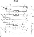
- each of the cells 1 to n is connected, respectively, to an n0 circuit 10 configured to provide an activatable / deactivatable voltage measurement circuit indicating the energy state of a particular cell. and a current bypass circuit passing through each activatable / deactivatable cell according to this energy state.
- a branch circuit 20 is connected in parallel with the cell 2.
- a conductor 21 forms a current bypass path from a polar terminal 2a of the cell 2 and is directed to the control medium 300 of the energy storage assembly 200 where it is connected to an activation / deactivation means 23.
- This activation / deactivation means 23 is also connected to a second track 22 which forms a current return path to the other polar terminal 2b of the cell 2.
- the activation / deactivation means 23 is a switch.
- activation / deactivation means 13 to n3 allows each branch circuit 10 to n0 to operate independently of the other circuits connected to the other cells.
- the activation / deactivation means 13 to n3 are able to electrically isolate the cell to be measured and at least one of the two cells adjacent to the cell to be measured.
- the activation / deactivation means 13 to n3 are able to electrically isolate the cell to be measured and each of the two cells adjacent to the cell to be measured.
- each branch circuit n0 is used as the measuring circuit of the corresponding cell, and conversely, the measurement circuit of a cell uses all or part of the branch circuit n0 of adjacent cells, which allows limit the number of conductors present on the support 101 and streamline the design and shape of the conductors present.
- each current n0 branch circuit includes at least one electrically resistive and thermally conductive element Rn acting as a current limiter.
- this element Rn is a resistor of energy dissipation.
- the activation / deactivation means 23 of the branch circuit 20 varies between a conductive state and a non-conductive state and derives a portion of the current flowing through the corresponding energy storage cell 2 to the dissipation resistors of the assembly 200 when in the conductive state.
- the routing of the branch circuits 10 to n0 is determined so as to connect the electrically resistive and thermally conductive elements Rn alternately on the positive pole terminal of an energy storage cell and on the negative terminal of the next energy storage cell to limit the number of conductors to be configured on the conductive surface of the interconnect medium 101.
- each cell 1 to n being connected in series with the other cells of the set 200 and the interconnection support 101, a voltage level is produced and can be measured by the health condition control medium 300. of the energy storage assembly 200.
- voltage measuring circuits for each of the energy storage cells 1 to n of the assembly 200 are integrated in the conductive circuit 800.
- these voltage measuring circuits are identical to the above-mentioned branching circuits 10 to 10.
- branch circuits 10 to 10 are not used for the voltage measurement since they would give a redundant measurement with a measurement already made. Thus, it is possible to reduce the number of measuring circuit of the control support 300 to monitor all the energy storage cells.
- the conductive tracks 11 and 12 forming the branch circuit 10 correspond to the conductive tracks defining the measurement path V1 of this particular cell 1.
- the measurement path of this particular cell 2 corresponds to the tracks 11 and 22.
- the potential detection lines 11 and 22 extend on either side of the cell 2 to a voltage detection circuit present on the control medium 300 of the state of health of the assembly 200.
- An example of the different potential measurement lines of an electrical circuit 800 configured for an interconnection system 100 according to the invention is represented on the figure 7 for a set 200 of twelve energy storage cells.
- the lines Vn + and Vn- represent, respectively, the potentials measured at the positive pole terminal 500 and at the negative pole terminal 500 of energy storage cells.
- the lines CPC1 to CPC12 represent, respectively, the potentials measured at the level of the conductive tracks comprising the energy dissipation resistors of the energy storage cells 1 to 12.
- the switches 13 to 13 are wired between each pair of tracks (Vn, CPCn) of a particular energy storage cell.
- the electrically conductive surface of interconnect carrier 101 is processed to present conductive printing 800 mentioned above in connection with the figures 6 and 7 .
- the electrical contact between the conductive printing 800 and the pole terminals 500 of the energy storage cells is produced, in a manner known per se, by welding, brazing or gluing.
- the brazed, welded or bonded contact is established by contacting an interconnection eyelet 152 of a cutout 150, having on its upper surface 157 stripped part of the conductive circuit 800, with the inner face 512 of the upper shoulder 510 of the polar terminal 500.
- the conductive tracks of each branch / measurement circuit 10 to n0 are configured to extend, from each cutout 110, 120 and 150, intended to receive the polar terminals 500. cells, longitudinally, along the length of the interconnection support 101 towards the end 102 near the control support 300.
- this electrical termination is a 930 connector crimped or welded on the interconnect carrier 101.
- connection area 940 comprising staple type contacts.
- one and the same interconnection eyelet is used to connect all the tracks coming from or leaving the terminals of adjacent cells connected to each other, thereby achieving a point of the same electrical potential.
- the conductive tracks defined by the presence of current limiting elements Rn, electrically resistive and thermally conductive, must have a given resistance.
- a pair length / width of track is chosen adapted to the resistivity that is sought.
- the energy dissipation resistors Rn consist of current paths of the conducting circuit 800 and, more precisely, of the measurement and derivation circuit of each cell 10 to n0, the value of said resistors Rn being constituted by the tracking resistance of the corresponding track between the terminal of the cell to be bypassed and the control system 300.
- the lengths of the energy dissipation resistances Rn associated with each cell, with a constant section, are chosen so as to be all identical, regardless of the positioning of the cell with respect to the interconnection system 100.
- the integration in the conductive circuit 800 of resistive elements R1 to Rn causes a dissipation of heat in the support 101 of the interconnection system 100.
- the distribution of the resistive tracks is optimized to best cover the entire surface of the interconnection support 101 in order to avoid a surface density of energy produced too much and not to unbalance the homogeneity thermal energy storage assembly 200.
- the tracking section of the tracks is chosen constant over their entire length in order to distribute the heat dissipation of each resistor over the entire interconnection system 100.
- dissipation resistor R1 to Rn associated with a given cell travels to the right of a maximum of adjacent cells, in order to best distribute the energy dissipated in the set of cells other than the bypassed cell.
- the energy recovered by these configurations by the energy storage cells contributes to maintaining the temperature of the energy storage assembly 200.
- the energy consumed by the heating plates for the thermal regulation of the assembly 200 is thus advantageously diminished.
- the return tracks having to have a maximum value lower than a threshold set by the operation of the control system 300, the said return tracks are made with a widest possible section and a shortest and most possible right between the terminal of the connected cell and the control system 300, taking into account the congestion of the interconnection support 101, to minimize the value of the resistance of each return track.
- the interconnection system 100 is, in addition, glued or plated by the compression of a thickness of an elastic material on the tops of the cells in order to optimize the thermal coupling.
- the material is of elastomeric or cellular type.
- An alternative embodiment of the invention provides for increasing or decreasing the thickness of the conductive surface to obtain the best compromise of cross section of the conductive tracks if the conductive surface of the interconnection support 101 is not sufficient to make the compromises. between width and length of conductors.
- the interconnection system 100 also includes a shield 910 to protect the printing conductive 800 electromagnetic disturbances.
- the shield 910 is a layer of conductive material separated from the conductive printing 800 by an insulating layer 900, as illustrated in FIG. figure 8 .
- the shielding layer 910 may cover the entire interconnection support 100, with the exception of the retaining means 110, 120 and 150 and the connection zone 940 of the conductive circuit 800 with the electronic support. 300.
- this shielding layer of potential Vss is electrically connected, towards the end 102 near the control support 300, to the ground plane of the latter via the connector 930.
- Embodiments of the present invention relate to an interconnect system 100 having an interconnect carrier 101 of double-sided or multilayer structure.
- multilayer interconnection support 101 would comprise three conductive layers configured, each, respectively, to present the resistive conductive tracks, the shield and the current return tracks.
- the disposition, the nature, the number of layers can be the subject of numerous variants.
- Another alternative embodiment provides for the presence of zones on the interconnection support for mounting electronic components and, more particularly, CMS type components.
- the energy storage cells connected in series and interconnected with the interconnection system 100 produce a charging current delivered to an energy consuming element.
- each branch circuit 10 to n0 controlled by the control medium 300 remains in an unactivated state so as not to interrupt the flow of current through the connected cells.
- the bypass circuit no dedicated to that cell is activated and the charging current bypasses the defective cell n to its voltage decreases to be brought to the other energy storage cells. This bypass will dissipate energy over the entire surface of the interconnect system 100.
- Nonlimiting examples include lithium polymer, nickel metal hybrid or lithium ion technologies.
- interconnection system 100 has a flexibility to adapt its configuration to the energy storage assembly 200 which it is intended while providing a precise electrical connection.
- the interconnection system 100 offers the advantage of having non-unitary energy dissipation resistors R1 to Rn which, on the one hand, make it possible to efficiently derive the current in the presence of a defective cell and on the other hand to improve the thermal regulation of the energy storage assembly 200.
Landscapes
- Chemical & Material Sciences (AREA)
- Chemical Kinetics & Catalysis (AREA)
- Electrochemistry (AREA)
- General Chemical & Material Sciences (AREA)
- Inorganic Chemistry (AREA)
- Connection Of Batteries Or Terminals (AREA)
- Charge And Discharge Circuits For Batteries Or The Like (AREA)
Applications Claiming Priority (2)
| Application Number | Priority Date | Filing Date | Title |
|---|---|---|---|
| FR0507527A FR2888669B1 (fr) | 2005-07-13 | 2005-07-13 | Systeme d'interconnexion pour un ensemble de stockage d'energie |
| PCT/FR2006/001572 WO2007006898A1 (fr) | 2005-07-13 | 2006-07-04 | Systeme d’interconnexion pour un ensemble de stockage d’energie |
Publications (2)
| Publication Number | Publication Date |
|---|---|
| EP1902483A1 EP1902483A1 (fr) | 2008-03-26 |
| EP1902483B1 true EP1902483B1 (fr) | 2018-08-22 |
Family
ID=36371029
Family Applications (1)
| Application Number | Title | Priority Date | Filing Date |
|---|---|---|---|
| EP06778759.8A Not-in-force EP1902483B1 (fr) | 2005-07-13 | 2006-07-04 | Systeme d interconnexion pour un ensemble de stockage d energie |
Country Status (6)
| Country | Link |
|---|---|
| US (1) | US8431260B2 (enExample) |
| EP (1) | EP1902483B1 (enExample) |
| JP (1) | JP5666090B2 (enExample) |
| CA (1) | CA2615035C (enExample) |
| FR (1) | FR2888669B1 (enExample) |
| WO (1) | WO2007006898A1 (enExample) |
Families Citing this family (10)
| Publication number | Priority date | Publication date | Assignee | Title |
|---|---|---|---|---|
| FR2916306B1 (fr) * | 2007-05-15 | 2009-07-17 | Batscap Sa | Module pour ensembles de stockage d'energie electrique permettant la detection du vieillissement desdits ensembles. |
| US20100028761A1 (en) * | 2008-07-30 | 2010-02-04 | C&D Technologies, Inc. | Storage battery terminal having test surface |
| AT515298B1 (de) * | 2014-01-31 | 2015-08-15 | Avl List Gmbh | Verbindungselement zum Kontaktieren von zumindest einem Zellpol einer Batteriezelle |
| KR102320437B1 (ko) * | 2015-03-03 | 2021-11-01 | 삼성에스디아이 주식회사 | 플렉서블 이차 전지 |
| CN107068953A (zh) * | 2015-12-30 | 2017-08-18 | 昶洧新能源汽车发展有限公司 | 用于电动车辆电池组的集成汇流条和电池连接 |
| US9966586B2 (en) * | 2015-12-30 | 2018-05-08 | Thunder Power New Energy Vehicle Development Company Limited | Integrated busbar and battery connection for electric vehicle battery packs |
| CN105655536A (zh) * | 2016-03-18 | 2016-06-08 | 宁德时代新能源科技股份有限公司 | 一种极耳垫板 |
| JP7041842B2 (ja) | 2018-03-26 | 2022-03-25 | トヨタ自動車株式会社 | 組電池および組電池の製造方法 |
| AU2020367536A1 (en) * | 2019-10-16 | 2022-05-12 | Relectrify Holdings Pty Ltd | Electronics assembly |
| CN112331983B (zh) * | 2019-11-29 | 2021-10-08 | 宁德时代新能源科技股份有限公司 | 电池模块、装置及失效电池单体的失效处理方法 |
Family Cites Families (13)
| Publication number | Priority date | Publication date | Assignee | Title |
|---|---|---|---|---|
| GB359441A (en) * | 1930-07-21 | 1931-10-21 | John William Manley | Improvements in electric batteries |
| US3932689A (en) * | 1973-10-13 | 1976-01-13 | Sumitomo Bakelite Company, Limited | Flexible adhesive composition and method for utilizing same and article formed therefrom |
| US4065710A (en) * | 1975-08-25 | 1977-12-27 | Zytka Bernard J | Substitute power supply and battery charger for battery operated apparatus |
| US5223690A (en) * | 1990-11-29 | 1993-06-29 | Alexander Manufacturing Company | Process and apparatus for spot-welding a flexible welding board to a battery cell |
| US5825155A (en) * | 1993-08-09 | 1998-10-20 | Kabushiki Kaisha Toshiba | Battery set structure and charge/ discharge control apparatus for lithium-ion battery |
| JP3272154B2 (ja) * | 1994-07-15 | 2002-04-08 | 三洋電機株式会社 | バッテリーパック |
| US5469002A (en) * | 1994-08-31 | 1995-11-21 | Motorola, Inc. | Bi-level current limiting circuit and battery using same |
| JPH10271705A (ja) * | 1997-03-28 | 1998-10-09 | Mitsubishi Electric Corp | 電源回路 |
| US5892351A (en) * | 1997-08-29 | 1999-04-06 | Compaq Computer Corporation | DC-isolated converting battery module |
| ATE333207T1 (de) * | 1998-11-09 | 2006-08-15 | Ballard Power Systems | Elektrische kontaktvorrichtung für eine brennstoffzelle |
| DE10002142B4 (de) * | 1999-01-28 | 2004-04-29 | Sanyo Electric Co., Ltd., Moriguchi | Stromversorgung enthaltend wiederaufladbare Batterien |
| JP2001068078A (ja) * | 1999-06-22 | 2001-03-16 | Hudson Soft Co Ltd | 電 池 |
| TWI299591B (en) * | 2002-03-20 | 2008-08-01 | Nec Tokin Corp | Battery pack |
-
2005
- 2005-07-13 FR FR0507527A patent/FR2888669B1/fr not_active Expired - Fee Related
-
2006
- 2006-07-04 WO PCT/FR2006/001572 patent/WO2007006898A1/fr not_active Ceased
- 2006-07-04 US US11/988,959 patent/US8431260B2/en not_active Expired - Fee Related
- 2006-07-04 JP JP2008520907A patent/JP5666090B2/ja not_active Expired - Fee Related
- 2006-07-04 CA CA2615035A patent/CA2615035C/fr not_active Expired - Fee Related
- 2006-07-04 EP EP06778759.8A patent/EP1902483B1/fr not_active Not-in-force
Non-Patent Citations (1)
| Title |
|---|
| None * |
Also Published As
| Publication number | Publication date |
|---|---|
| FR2888669B1 (fr) | 2010-08-20 |
| WO2007006898A1 (fr) | 2007-01-18 |
| JP5666090B2 (ja) | 2015-02-12 |
| CA2615035A1 (fr) | 2007-01-18 |
| CA2615035C (fr) | 2012-01-10 |
| US20090035607A1 (en) | 2009-02-05 |
| US8431260B2 (en) | 2013-04-30 |
| FR2888669A1 (fr) | 2007-01-19 |
| JP2009501413A (ja) | 2009-01-15 |
| EP1902483A1 (fr) | 2008-03-26 |
Similar Documents
| Publication | Publication Date | Title |
|---|---|---|
| EP2375424B1 (fr) | Dispositif de protection contre les surtensions à déconnecteurs thermiques dédoublés | |
| EP2375426B1 (fr) | Varistance comprenant une électrode avec une partie en saillie formant pôle et parafoudre comprenant une telle varistance | |
| EP2034539B1 (fr) | Batterie constituée d'une pluralité de cellules positionnées et reliées entre elles, sans soudure | |
| EP2375425B1 (fr) | Dispositif de protection contre les surtensions transitoires à déconnecteur thermique amélioré | |
| EP3176918B1 (fr) | Architecture electronique destinee a alimenter une machine electrique pour vehicule automobile | |
| EP1902483B1 (fr) | Systeme d interconnexion pour un ensemble de stockage d energie | |
| EP2721911B1 (fr) | Circuit imprime pour l'interconnexion et la mesure d'accumulateurs d'une batterie | |
| EP1828786A1 (fr) | Dispositif de mesure d'un courant circulant dans un cable | |
| WO2012032230A1 (fr) | Ensemble de prises electriques | |
| FR3056022A1 (fr) | Dispositif d'interconnexion electrique d'elements de batterie et batterie d'accumulateurs pourvue d'un tel dispositif | |
| EP3871296A1 (fr) | Dispositif de connexion pour véhicule équipé d'un capteur de température | |
| FR2932318A1 (fr) | Embout de porte-balai et son application a la realisation d'un demarreur pour vehicule automobile | |
| WO1998043325A1 (fr) | Dispositif de distribution d'energie electrique dans plusieurs circuits alimentes en parallele, et procede de fabrication de ce dispositif | |
| FR3094148A1 (fr) | Dispositif de protection contre les surtensions | |
| EP2745661B1 (fr) | Dispositif de connexion electrique, ensemble comprenant un tel dispositif et une carte electronique et procede de connexion electrique d'une carte electronique | |
| FR3048906A1 (fr) | Procede de soudage entre un element conducteur et un pole de batterie et batteries assemblees avec un tel procede | |
| FR2934434A1 (fr) | Dispositif porte-balais pour demarreur d'un vehicule automobile | |
| EP0449729B1 (fr) | Résistance de puissance plate | |
| FR2748608A1 (fr) | Systeme electronique pour batterie bipolaire et carte pour ce systeme | |
| EP3672382B1 (fr) | Organe de plaquage, ensemble et equipement electrique | |
| WO2025087796A1 (fr) | Connecteur électrique entre au moins deux fils électriquement conducteurs et une carte de circuit imprimé | |
| CH721723A2 (fr) | Dispositif de connexion électrique à pinces | |
| EP1603199B1 (fr) | Dispositif de connexion électrique | |
| FR3012913A1 (fr) | Dispositif de connexion electrique en parallele d'elements electrochimiques | |
| EP4579991A1 (fr) | Ensemble d éléments électrochimiques à circulation de courant optimisée et batterie associé |
Legal Events
| Date | Code | Title | Description |
|---|---|---|---|
| PUAI | Public reference made under article 153(3) epc to a published international application that has entered the european phase |
Free format text: ORIGINAL CODE: 0009012 |
|
| 17P | Request for examination filed |
Effective date: 20080114 |
|
| AK | Designated contracting states |
Kind code of ref document: A1 Designated state(s): AT BE BG CH CY CZ DE DK EE ES FI FR GB GR HU IE IS IT LI LT LU LV MC NL PL PT RO SE SI SK TR |
|
| DAX | Request for extension of the european patent (deleted) | ||
| DAX | Request for extension of the european patent (deleted) | ||
| 17Q | First examination report despatched |
Effective date: 20130806 |
|
| RAP1 | Party data changed (applicant data changed or rights of an application transferred) |
Owner name: BLUE SOLUTIONS |
|
| STAA | Information on the status of an ep patent application or granted ep patent |
Free format text: STATUS: EXAMINATION IS IN PROGRESS |
|
| GRAP | Despatch of communication of intention to grant a patent |
Free format text: ORIGINAL CODE: EPIDOSNIGR1 |
|
| STAA | Information on the status of an ep patent application or granted ep patent |
Free format text: STATUS: GRANT OF PATENT IS INTENDED |
|
| INTG | Intention to grant announced |
Effective date: 20180301 |
|
| GRAS | Grant fee paid |
Free format text: ORIGINAL CODE: EPIDOSNIGR3 |
|
| GRAA | (expected) grant |
Free format text: ORIGINAL CODE: 0009210 |
|
| STAA | Information on the status of an ep patent application or granted ep patent |
Free format text: STATUS: THE PATENT HAS BEEN GRANTED |
|
| AK | Designated contracting states |
Kind code of ref document: B1 Designated state(s): AT BE BG CH CY CZ DE DK EE ES FI FR GB GR HU IE IS IT LI LT LU LV MC NL PL PT RO SE SI SK TR |
|
| REG | Reference to a national code |
Ref country code: GB Ref legal event code: FG4D Free format text: NOT ENGLISH |
|
| REG | Reference to a national code |
Ref country code: CH Ref legal event code: EP |
|
| REG | Reference to a national code |
Ref country code: AT Ref legal event code: REF Ref document number: 1033491 Country of ref document: AT Kind code of ref document: T Effective date: 20180915 |
|
| REG | Reference to a national code |
Ref country code: IE Ref legal event code: FG4D Free format text: LANGUAGE OF EP DOCUMENT: FRENCH |
|
| REG | Reference to a national code |
Ref country code: DE Ref legal event code: R096 Ref document number: 602006056153 Country of ref document: DE |
|
| REG | Reference to a national code |
Ref country code: NL Ref legal event code: MP Effective date: 20180822 |
|
| REG | Reference to a national code |
Ref country code: LT Ref legal event code: MG4D |
|
| PG25 | Lapsed in a contracting state [announced via postgrant information from national office to epo] |
Ref country code: GR Free format text: LAPSE BECAUSE OF FAILURE TO SUBMIT A TRANSLATION OF THE DESCRIPTION OR TO PAY THE FEE WITHIN THE PRESCRIBED TIME-LIMIT Effective date: 20181123 Ref country code: NL Free format text: LAPSE BECAUSE OF FAILURE TO SUBMIT A TRANSLATION OF THE DESCRIPTION OR TO PAY THE FEE WITHIN THE PRESCRIBED TIME-LIMIT Effective date: 20180822 Ref country code: SE Free format text: LAPSE BECAUSE OF FAILURE TO SUBMIT A TRANSLATION OF THE DESCRIPTION OR TO PAY THE FEE WITHIN THE PRESCRIBED TIME-LIMIT Effective date: 20180822 Ref country code: BG Free format text: LAPSE BECAUSE OF FAILURE TO SUBMIT A TRANSLATION OF THE DESCRIPTION OR TO PAY THE FEE WITHIN THE PRESCRIBED TIME-LIMIT Effective date: 20181122 Ref country code: LT Free format text: LAPSE BECAUSE OF FAILURE TO SUBMIT A TRANSLATION OF THE DESCRIPTION OR TO PAY THE FEE WITHIN THE PRESCRIBED TIME-LIMIT Effective date: 20180822 Ref country code: FI Free format text: LAPSE BECAUSE OF FAILURE TO SUBMIT A TRANSLATION OF THE DESCRIPTION OR TO PAY THE FEE WITHIN THE PRESCRIBED TIME-LIMIT Effective date: 20180822 Ref country code: IS Free format text: LAPSE BECAUSE OF FAILURE TO SUBMIT A TRANSLATION OF THE DESCRIPTION OR TO PAY THE FEE WITHIN THE PRESCRIBED TIME-LIMIT Effective date: 20181222 |
|
| REG | Reference to a national code |
Ref country code: AT Ref legal event code: MK05 Ref document number: 1033491 Country of ref document: AT Kind code of ref document: T Effective date: 20180822 |
|
| PG25 | Lapsed in a contracting state [announced via postgrant information from national office to epo] |
Ref country code: ES Free format text: LAPSE BECAUSE OF FAILURE TO SUBMIT A TRANSLATION OF THE DESCRIPTION OR TO PAY THE FEE WITHIN THE PRESCRIBED TIME-LIMIT Effective date: 20180822 Ref country code: LV Free format text: LAPSE BECAUSE OF FAILURE TO SUBMIT A TRANSLATION OF THE DESCRIPTION OR TO PAY THE FEE WITHIN THE PRESCRIBED TIME-LIMIT Effective date: 20180822 |
|
| PG25 | Lapsed in a contracting state [announced via postgrant information from national office to epo] |
Ref country code: AT Free format text: LAPSE BECAUSE OF FAILURE TO SUBMIT A TRANSLATION OF THE DESCRIPTION OR TO PAY THE FEE WITHIN THE PRESCRIBED TIME-LIMIT Effective date: 20180822 Ref country code: IT Free format text: LAPSE BECAUSE OF FAILURE TO SUBMIT A TRANSLATION OF THE DESCRIPTION OR TO PAY THE FEE WITHIN THE PRESCRIBED TIME-LIMIT Effective date: 20180822 Ref country code: RO Free format text: LAPSE BECAUSE OF FAILURE TO SUBMIT A TRANSLATION OF THE DESCRIPTION OR TO PAY THE FEE WITHIN THE PRESCRIBED TIME-LIMIT Effective date: 20180822 Ref country code: EE Free format text: LAPSE BECAUSE OF FAILURE TO SUBMIT A TRANSLATION OF THE DESCRIPTION OR TO PAY THE FEE WITHIN THE PRESCRIBED TIME-LIMIT Effective date: 20180822 Ref country code: CZ Free format text: LAPSE BECAUSE OF FAILURE TO SUBMIT A TRANSLATION OF THE DESCRIPTION OR TO PAY THE FEE WITHIN THE PRESCRIBED TIME-LIMIT Effective date: 20180822 Ref country code: PL Free format text: LAPSE BECAUSE OF FAILURE TO SUBMIT A TRANSLATION OF THE DESCRIPTION OR TO PAY THE FEE WITHIN THE PRESCRIBED TIME-LIMIT Effective date: 20180822 |
|
| REG | Reference to a national code |
Ref country code: DE Ref legal event code: R097 Ref document number: 602006056153 Country of ref document: DE |
|
| PG25 | Lapsed in a contracting state [announced via postgrant information from national office to epo] |
Ref country code: SK Free format text: LAPSE BECAUSE OF FAILURE TO SUBMIT A TRANSLATION OF THE DESCRIPTION OR TO PAY THE FEE WITHIN THE PRESCRIBED TIME-LIMIT Effective date: 20180822 Ref country code: DK Free format text: LAPSE BECAUSE OF FAILURE TO SUBMIT A TRANSLATION OF THE DESCRIPTION OR TO PAY THE FEE WITHIN THE PRESCRIBED TIME-LIMIT Effective date: 20180822 |
|
| PLBE | No opposition filed within time limit |
Free format text: ORIGINAL CODE: 0009261 |
|
| STAA | Information on the status of an ep patent application or granted ep patent |
Free format text: STATUS: NO OPPOSITION FILED WITHIN TIME LIMIT |
|
| 26N | No opposition filed |
Effective date: 20190523 |
|
| PG25 | Lapsed in a contracting state [announced via postgrant information from national office to epo] |
Ref country code: SI Free format text: LAPSE BECAUSE OF FAILURE TO SUBMIT A TRANSLATION OF THE DESCRIPTION OR TO PAY THE FEE WITHIN THE PRESCRIBED TIME-LIMIT Effective date: 20180822 |
|
| PG25 | Lapsed in a contracting state [announced via postgrant information from national office to epo] |
Ref country code: MC Free format text: LAPSE BECAUSE OF FAILURE TO SUBMIT A TRANSLATION OF THE DESCRIPTION OR TO PAY THE FEE WITHIN THE PRESCRIBED TIME-LIMIT Effective date: 20180822 |
|
| REG | Reference to a national code |
Ref country code: CH Ref legal event code: PL |
|
| PG25 | Lapsed in a contracting state [announced via postgrant information from national office to epo] |
Ref country code: TR Free format text: LAPSE BECAUSE OF FAILURE TO SUBMIT A TRANSLATION OF THE DESCRIPTION OR TO PAY THE FEE WITHIN THE PRESCRIBED TIME-LIMIT Effective date: 20180822 |
|
| REG | Reference to a national code |
Ref country code: BE Ref legal event code: MM Effective date: 20190731 |
|
| PG25 | Lapsed in a contracting state [announced via postgrant information from national office to epo] |
Ref country code: BE Free format text: LAPSE BECAUSE OF NON-PAYMENT OF DUE FEES Effective date: 20190731 Ref country code: LI Free format text: LAPSE BECAUSE OF NON-PAYMENT OF DUE FEES Effective date: 20190731 Ref country code: CH Free format text: LAPSE BECAUSE OF NON-PAYMENT OF DUE FEES Effective date: 20190731 Ref country code: LU Free format text: LAPSE BECAUSE OF NON-PAYMENT OF DUE FEES Effective date: 20190704 |
|
| PG25 | Lapsed in a contracting state [announced via postgrant information from national office to epo] |
Ref country code: PT Free format text: LAPSE BECAUSE OF FAILURE TO SUBMIT A TRANSLATION OF THE DESCRIPTION OR TO PAY THE FEE WITHIN THE PRESCRIBED TIME-LIMIT Effective date: 20181222 |
|
| PG25 | Lapsed in a contracting state [announced via postgrant information from national office to epo] |
Ref country code: IE Free format text: LAPSE BECAUSE OF NON-PAYMENT OF DUE FEES Effective date: 20190704 |
|
| PGFP | Annual fee paid to national office [announced via postgrant information from national office to epo] |
Ref country code: FR Payment date: 20200716 Year of fee payment: 15 Ref country code: DE Payment date: 20200806 Year of fee payment: 15 Ref country code: GB Payment date: 20200820 Year of fee payment: 15 |
|
| REG | Reference to a national code |
Ref country code: DE Ref legal event code: R079 Ref document number: 602006056153 Country of ref document: DE Free format text: PREVIOUS MAIN CLASS: H01M0002200000 Ipc: H01M0050500000 |
|
| PG25 | Lapsed in a contracting state [announced via postgrant information from national office to epo] |
Ref country code: CY Free format text: LAPSE BECAUSE OF FAILURE TO SUBMIT A TRANSLATION OF THE DESCRIPTION OR TO PAY THE FEE WITHIN THE PRESCRIBED TIME-LIMIT Effective date: 20180822 |
|
| PG25 | Lapsed in a contracting state [announced via postgrant information from national office to epo] |
Ref country code: HU Free format text: LAPSE BECAUSE OF FAILURE TO SUBMIT A TRANSLATION OF THE DESCRIPTION OR TO PAY THE FEE WITHIN THE PRESCRIBED TIME-LIMIT; INVALID AB INITIO Effective date: 20060704 |
|
| REG | Reference to a national code |
Ref country code: DE Ref legal event code: R119 Ref document number: 602006056153 Country of ref document: DE |
|
| GBPC | Gb: european patent ceased through non-payment of renewal fee |
Effective date: 20210704 |
|
| PG25 | Lapsed in a contracting state [announced via postgrant information from national office to epo] |
Ref country code: GB Free format text: LAPSE BECAUSE OF NON-PAYMENT OF DUE FEES Effective date: 20210704 Ref country code: DE Free format text: LAPSE BECAUSE OF NON-PAYMENT OF DUE FEES Effective date: 20220201 |
|
| PG25 | Lapsed in a contracting state [announced via postgrant information from national office to epo] |
Ref country code: FR Free format text: LAPSE BECAUSE OF NON-PAYMENT OF DUE FEES Effective date: 20210731 |