EP1902437B1 - Systeme de feux de signalisation, en particulier pour la circulation routiere - Google Patents
Systeme de feux de signalisation, en particulier pour la circulation routiere Download PDFInfo
- Publication number
- EP1902437B1 EP1902437B1 EP06764037A EP06764037A EP1902437B1 EP 1902437 B1 EP1902437 B1 EP 1902437B1 EP 06764037 A EP06764037 A EP 06764037A EP 06764037 A EP06764037 A EP 06764037A EP 1902437 B1 EP1902437 B1 EP 1902437B1
- Authority
- EP
- European Patent Office
- Prior art keywords
- light
- signal
- control unit
- emitting diodes
- traffic
- Prior art date
- Legal status (The legal status is an assumption and is not a legal conclusion. Google has not performed a legal analysis and makes no representation as to the accuracy of the status listed.)
- Not-in-force
Links
Images
Classifications
-
- H—ELECTRICITY
- H05—ELECTRIC TECHNIQUES NOT OTHERWISE PROVIDED FOR
- H05B—ELECTRIC HEATING; ELECTRIC LIGHT SOURCES NOT OTHERWISE PROVIDED FOR; CIRCUIT ARRANGEMENTS FOR ELECTRIC LIGHT SOURCES, IN GENERAL
- H05B45/00—Circuit arrangements for operating light-emitting diodes [LED]
- H05B45/50—Circuit arrangements for operating light-emitting diodes [LED] responsive to malfunctions or undesirable behaviour of LEDs; responsive to LED life; Protective circuits
- H05B45/58—Circuit arrangements for operating light-emitting diodes [LED] responsive to malfunctions or undesirable behaviour of LEDs; responsive to LED life; Protective circuits involving end of life detection of LEDs
-
- H—ELECTRICITY
- H05—ELECTRIC TECHNIQUES NOT OTHERWISE PROVIDED FOR
- H05B—ELECTRIC HEATING; ELECTRIC LIGHT SOURCES NOT OTHERWISE PROVIDED FOR; CIRCUIT ARRANGEMENTS FOR ELECTRIC LIGHT SOURCES, IN GENERAL
- H05B45/00—Circuit arrangements for operating light-emitting diodes [LED]
- H05B45/50—Circuit arrangements for operating light-emitting diodes [LED] responsive to malfunctions or undesirable behaviour of LEDs; responsive to LED life; Protective circuits
- H05B45/52—Circuit arrangements for operating light-emitting diodes [LED] responsive to malfunctions or undesirable behaviour of LEDs; responsive to LED life; Protective circuits in a parallel array of LEDs
-
- H—ELECTRICITY
- H05—ELECTRIC TECHNIQUES NOT OTHERWISE PROVIDED FOR
- H05B—ELECTRIC HEATING; ELECTRIC LIGHT SOURCES NOT OTHERWISE PROVIDED FOR; CIRCUIT ARRANGEMENTS FOR ELECTRIC LIGHT SOURCES, IN GENERAL
- H05B45/00—Circuit arrangements for operating light-emitting diodes [LED]
- H05B45/50—Circuit arrangements for operating light-emitting diodes [LED] responsive to malfunctions or undesirable behaviour of LEDs; responsive to LED life; Protective circuits
- H05B45/54—Circuit arrangements for operating light-emitting diodes [LED] responsive to malfunctions or undesirable behaviour of LEDs; responsive to LED life; Protective circuits in a series array of LEDs
Definitions
- the invention relates to a traffic signal system for traffic, according to the preamble of claim 1.
- Traffic light systems are mainly used in traffic engineering for traffic control and regulation.
- Signalers which are intended to emit traffic signals for road users are known, above all, from road traffic.
- the competing traffic streams crossing at a junction of the road network which may be formed by motor vehicles, rail vehicles, cyclists and pedestrians, are controlled by a plurality of signalers.
- the signal generator are connected to a control unit, by which they are controlled by a signal program running in the control unit.
- a typical error is the unwanted absence of a blocking signal, for example a red light signal at a traffic light.
- Conventional control units use incandescent lamps for the electrical power supply as a reliable indicator of sufficient light generation in the filament.
- the performance of incandescent lamps of at least 20 W ensures an electric current that can be reliably monitored even in an extensive traffic signal system with earth cabling by the circuit device in the control unit.
- signal transmitters with LEDs a short circuit - current without voltage - or a current path interruption - voltage without current - can occur as a fault in a light emitting diode. It can also happen that a light-emitting diode does not emit light despite normal electrical operating values.
- Another type of error is the unwanted appearance of a release signal, such as the green light of a crossing traffic light.
- a conventional control unit monitors to detect this type of error, the signal line on exceeding a voltage of about 60 V at a nominal value of 230 V and assumes when falling below this limit that the bulb is not lit.
- the incandescent lamp absorbs noticeable energy even at 60 V, it hardly emits light in the visible spectral range.
- signal transmitters with light-emitting diodes on the other hand, it must be expected that even a very low power consumption leads to the illumination of a light-emitting diode, in particular at night.
- incandescent light-emitting diodes by capacitive coupling be illuminated in the line network of the signal generator.
- the driver circuit that is to say the energy converter
- the driver circuit can be equipped with an additional monitoring circuit which burns a special fuse in the case of faulty electrical operating values of the light-emitting diodes; With this so-called end-of-life circuit, the current consumption of the signal generator is interrupted analogously to the thread breakage of a light bulb.
- each additional monitoring circuit itself is also a potential source of error and that the operational readiness of an end-of-life monitoring circuit can not be tested during normal operation of the signaling device. It is also possible to dispense with the LED-specific energy savings and increase the electrical power through additional consumer resistance, while safety is to pay attention to the careful monitoring of the light-emitting diodes.
- Another solution provides for a reduction of the operating voltage - about 40 V instead of 230 V - in order to raise the monitored LED currents back to a well-monitored level. However, even in the foreseeable future, this method will reach its limits under the operating conditions of a control unit, since the technological trend in light-emitting diodes is leading to ever lower energy consumption.
- the traffic control unit controls up to 48 signal groups by means of a processor system.
- the signal protection is monitored by two independent microprocessors fail-safe according to VDE0832, which completely excludes traffic-endangering signaling states.
- the control unit has an interface to a higher-level traffic control center. In addition, more than 80 traffic detectors can be connected.
- a central circuit device which consists of lamp switches for each of eight signal groups of signal transmitters.
- a two-channel design is selected, whereby the occurrence of hazardous signaling states is monitored and contradictory signaling states and defective lamps are reported. If a dangerous signaling state occurs, the partial node in which this state has occurred is switched off via switch-off means.
- power LEDs are available as a central light source.
- the electrical interface to the control unit forms a current-monitored driver circuit with energy converter and end-of-life fuse.
- An LED signal generator has a housing with integrated cooling plate, in which an LED board and its energy supply, an energy converter are arranged.
- the housing is closed at the front by an optical lens and a front lens.
- Each signal generator is connected separately from its central lamp switch in the control unit with up to 250 m long 230 V underground cables as power supply line, which are exposed to considerable electrical interference.
- the decreasing power consumption of the LED signal heads makes secure monitoring ever more difficult, increases the risk of interference-related shutdowns and thus reduces the availability of the traffic signal system.
- the traffic signal is with at least equipped with a signal generator whose light source is formed by arranged in the form of a matrix LEDs.
- a signal generator whose light source is formed by arranged in the form of a matrix LEDs.
- each signal generator is connected to a switching and evaluation device, which in turn is connected to a device control.
- the device controller controls the operating states of the signal generator according to a predetermined signal plan.
- the switching and evaluation device generates signal control signals for switching on and off of signal diodes of the signal transmitters and test control signals for switching on or off a test diode. From the signal generator, the switching and evaluation device receives a light sensor signal from a light sensor for monitoring the function of the signal generator, which receives light from the test diode.
- the switching on and off as well as the monitoring of the signal transmitter are thus carried out for all signal generator of the traffic signal system centrally from their device control with switching and evaluation.
- the signal generator control associated with each signal generator which is arranged directly in the housing of the signal generator, it is an LED driver.
- the invention is therefore an object of the invention to provide a traffic signal of the type mentioned, the despite using signalers with LEDs as fail-safe and easy to set up.
- the above object is achieved by a generic traffic signal system, which has the characterizing features of claim 1.
- a generic traffic signal system which has the characterizing features of claim 1.
- very short cable lengths result in the critical line part, resulting in a drastic reduction of all interference on the voltages and currents of the LED signal.
- the wiring harness can be formed in an advantageous manner as an energy and data bus between the control unit and the signal generators.
- circuit means in addition to means for controlling the light-emitting diodes also means for converting the LEDs to be supplied energy and means for monitoring the current and / orchrosbeetzschlagung the light-emitting diodes, which are designed as a common module, the functions of the previously centrally arranged circuit devices and the Driver circuit fused in the signal generator, which advantageously avoids the multiple execution and concatenation of circuits for current and voltage monitoring.
- This makes the entire concept easier and easier to certify in terms of safety.
- the end-of-life circuit previously used in the driver can be completely eliminated. In practical operation, thereby increasing availability and security, while the manufacturing costs are reduced by the lower circuit complexity.
- Driving means of the circuit device are set up to control the signal outputs according to the signal controller's default settings.
- Evaluation means of the circuit device are designed to detect operating parameters redundantly and to carry out functional tests.
- Communication means of the circuit device are designed to exchange control, measurement and status data via a logical, secure data connection with the control unit. Through targeted functional checks and a coordinated division of tasks with the control unit, a failsafe design is achieved with economic outlay.
- the drive means are triggered by a logical command to modulate the pulse width and / or to reduce the amplitude of the light-emitting diodes to supply current. This allows a software-controlled fine-level dimming of the LEDs, with even individual about acoustic signals can be excluded when dimming.
- the circuit device is designed for a plurality of signal outputs.
- several signal outputs can always share the necessary core components, such as serial interface, microcontroller, energy converter.
- the ratio of net data to gross data that is, date and preamble, header, CRC, becomes more favorable in the resulting data telegrams between the control unit and the signalers.
- means for direct measurement of the electrical operating parameters of the light-emitting diodes are provided for monitoring the signal states.
- the electrical operating parameters are the current and voltage during operation of the diodes.
- means are provided for detecting the light emitted by the light-emitting diodes, which are designed to carry out tests in the switched-on and / or switched-off state of the light-emitting diodes.
- the switched-on state short switch-off phases may be provided, while in the switched-off state, a light emitting diode emitting in the infrared is activated for a short time.
- the data transmission between the control unit and signal generator via a 230 V power cable since 230 V cables are often used for data transmission, no new data cables need to be laid, which would be associated with complex and often traffic-obstructing civil engineering work. As a result, the known use of a coaxial cable is avoided, which was associated with correspondingly expensive connection assemblies.
- a common signal line is provided for the energy supply and the data transmission between the signal generator and the control device.
- a Powerline Communication (PLC) tailored to the application of the control unit is particularly suitable for ensuring reliable and efficient data transmission over the entire area of the traffic signal system on existing power cables.
- PLC technology tolerates a network with technical problem areas such as unfinished lines, spur lines or branches.
- the signal lines are used for energy and data transmission.
- the number of connection points is particularly low.
- separate signal lines are provided in light signaling systems according to the invention for the power supply and the data transmission between the signal generator and the control unit.
- separate signal lines there are more connection points, but you have a higher transmission quality and also savings, because the PLC transmitters much easier and the energy converter can be run without PLC high-frequency filter.
- a traffic detector arranged in the vicinity thereof can be connected to the signal transmitter, wherein traffic data detected by the traffic detector can be transmitted via the circuit devices to the control device. More and more frequently, for example, overhead traffic detectors are used, which are mounted in the area of the signal generator of a traffic signal system. In the proposed technique, no extra cables are required, but the detector outputs can be detected via special inputs of the circuit devices and transmitted from there to the control unit.
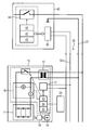
- the traffic signal system according to the invention for traffic control at a junction of the road traffic network comprises a plurality of signal transmitters 10, one of which is shown by way of example, a traffic detector 20 which can be arranged overhead on a signal mast, the signal transmitters 10 according to the invention via one, possibly a single, Wiring harness 30 are connected to a controller 40.
- a signal generator 10 has at least one light emitting diode 11 for emitting a light signal - such as green, yellow or red light - which can be controlled by a arranged in or on the signal generator 10 circuit device.
- the length of the line 30 is shortened, which in particular in the critical line part to a drastic Reduction of all interference to the voltages and currents of the LED signal leads.
- the circuit device in the signal transmitter 10 implements a simple and easily certifiable safety concept, in which the functions of the lamp switches previously arranged centrally in the control unit 40 and the driver circuits arranged in the signal generators 10 are merged.
- a circuit device comprises an energy converter 12 for the light emitting diodes 11, which is connected to the power supply lines 31 of the wiring harness 30.
- the drive means 13 of the circuit device are triggered by a logic command for pulse width modulation and / or for lowering the amplitude of the light emitting diodes 11 to be supplied current I formed. This allows a software-controlled fine-level dimming of the LEDs 11.
- the control means 13 control the signal outputs, preferably a plurality of signal outputs, according to target specifications.
- evaluation means 14 operating parameters can be detected redundant and functional tests are performed.
- monitoring means 16 are provided, by means of which current and voltage application of the light-emitting diodes 11 can be measured.
- control, measurement and status data are exchanged with the control unit 40 via a logically secured data connection.
- each signal generator 10 comprises a serial interface 17, which has a formed as a data bus line connection 32 is connected to a serial interface 45 of the controller 40.
- this light detection means 18 which can be formed for example by a photodiode.
- a short-term switching off of the LEDs 11 can take place here, for example, during operation.
- a light-emitting diode 19 emitting in the infrared range is provided on the signal generator 10 of the illustrated embodiment, the radiation of which can likewise be detected by the detection means 18 and processed in the evaluation means 14.
- the known indirect inference from the electric diode current to the luminous flux is no longer necessary.
- the luminosity of the signal generator 10 can be monitored regardless of the number and efficiency of the LEDs 11.
- the output data of the traffic detector 20 can be detected via special inputs of the peripheral circuit device and transmitted from there via the wiring harness 30 to the control unit 40.
Landscapes
- Traffic Control Systems (AREA)
- Road Signs Or Road Markings (AREA)
Claims (7)
- Système de feux de signalisation pour la circulation routière,- comprenant au moins un émetteur ( 10 ) de signaux ayant des diodes ( 11 ) électroluminescentes pour l'émission d'un signe lumineux,- comprenant un appareil ( 40 ) de commande pour commander, exploiter et contrôler l'émetteur ( 10 ) de signaux,- et comprenant des lignes ( 31 ) d'alimentation en énergie entre l'appareil ( 40 ) de commande et l'émetteur ( 10 ) de signaux,caractérisé- en ce qu'il est prévu pour chaque émetteur ( 10 ) de signaux un circuit disposé à proximité immédiate dans ou sur l'émetteur ( 10 ) de signaux et conçu pour plusieurs sorties du signal et qui comportequi sont constitués en module commun,- des moyens ( 13 ) de commande des diodes ( 11 ) électroluminescentes conçus pour commander des sorties de signaux en fonction de prescriptions de consigne du dispositif de commande,- des moyens ( 12 ) de transformation de l'énergie apportée aux diodes ( 11 ) électroluminescentes,- des moyens ( 14 ) de contrôle de l'alimentation en courant et/ou en tension des diodes ( 11 ) électroluminescentes, qui sont conçus pour détecter de manière redondante des paramètres de fonctionnement et effectuer des tests de fonction,- et des moyens ( 15 ) de communication qui sont constitués pour échanger des données de commande de mesure et d'état avec l'appareil ( 40 ) de commande par une liaison de données logique et sécurisée,- en ce que les émetteurs ( 10 ) de signaux sont reliés à l'appareil ( 40 ) de commande par une branche ( 30 ) de ligne unique ayant les lignes ( 31 ) d'alimentation en énergie et les lignes ( 32 ) de transmission de données,- et en ce que les lignes ( 32 ) de transmission de données entre l'appareil ( 40 ) de commande et au moins un émetteur ( 10 ) de signaux sont réalisées en câbles de courant à la terre, l'appareil ( 40 ) de commande et l'émetteur ( 10 ) de signaux étant constitués pour la transmission de données au moyen d'une Powerline Communication.
- Système de feux de signalisation suivant la revendication 1,
caractérisé en ce que les moyens ( 13 ) de commande sont constitués en étant déclenchés par une instruction logique pour la modulation de la largeur des impulsions et/ou pour la diminution de l'amplitude du courant ( I ) envoyé aux diodes ( 11 ) électroluminescentes. - Système de feux de signalisation suivant la revendication 1 ou 2,
caractérisé en ce qu'il est prévu, pour le contrôle des états du signal, des moyens ( 16 ) de mesure directe du courant ( I ) alimentant les diodes ( 11 ) électroluminescentes. - Système de feux de signalisation suivant l'une des revendications 1 à 3,
caractérisé en ce qu'il est prévu des moyens de détection de la lumière émise par les diodes ( 11 ) électroluminescentes, moyens qui sont constitués pour la réalisation de tests alors que les diodes ( 11 ) électroluminescentes sont mises en circuit et/ou mises hors circuit. - Système de feux de signalisation suivant l'une des revendications 1 à 4,
caractérisé en ce qu'il est prévu une ligne de signal commune pour l'alimentation en énergie et la transmission des données entre un émetteur ( 10 ) de signaux et l'appareil ( 40 ) de commande. - Système de feux de signalisation suivant l'une des revendications 1 à 4,
caractérisé en ce qu'il est prévu des lignes ( 31 et 32 ) de signal distinctes l'une de l'autre pour l'alimentation en énergie et la transmission de données entre l'émetteur ( 10 ) de signaux et l'appareil ( 40 ) de commande. - Système de feux de signalisation suivant l'une des revendications 1 à 6,
caractérisé en ce qu'à l'émetteur ( 10 ) de signaux peut être raccordé un détecteur ( 20 ) de circulation disposé à sa proximité immédiate, des données de circulation détectées par le détecteur ( 20 ) de circulation pouvant être transmises à l'appareil ( 40 ) de commande par le circuit.
Applications Claiming Priority (2)
| Application Number | Priority Date | Filing Date | Title |
|---|---|---|---|
| DE102005032719A DE102005032719A1 (de) | 2005-07-13 | 2005-07-13 | Lichtsignalanlage, insbesondere für den Straßenverkehr |
| PCT/EP2006/063833 WO2007006684A1 (fr) | 2005-07-13 | 2006-07-04 | Systeme de feux de signalisation, en particulier pour la circulation routiere |
Publications (2)
| Publication Number | Publication Date |
|---|---|
| EP1902437A1 EP1902437A1 (fr) | 2008-03-26 |
| EP1902437B1 true EP1902437B1 (fr) | 2011-03-02 |
Family
ID=37062532
Family Applications (1)
| Application Number | Title | Priority Date | Filing Date |
|---|---|---|---|
| EP06764037A Not-in-force EP1902437B1 (fr) | 2005-07-13 | 2006-07-04 | Systeme de feux de signalisation, en particulier pour la circulation routiere |
Country Status (4)
| Country | Link |
|---|---|
| EP (1) | EP1902437B1 (fr) |
| AT (1) | ATE500583T1 (fr) |
| DE (2) | DE102005032719A1 (fr) |
| WO (1) | WO2007006684A1 (fr) |
Families Citing this family (5)
| Publication number | Priority date | Publication date | Assignee | Title |
|---|---|---|---|---|
| DE102007047847B4 (de) * | 2007-11-22 | 2018-02-22 | Swarco Traffic Systems Gmbh | Verkehrssignalanlage mit Signalgebern und einer Steuereinrichtung zum Steuern von Leuchten in den Signalgebern |
| DK2581311T3 (en) * | 2011-10-10 | 2014-03-17 | Hella Kgaa Hueck & Co | LED airfield |
| WO2016050521A1 (fr) * | 2014-09-29 | 2016-04-07 | Siemens Aktiengesellschaft | Dispositif et procédé pour contrôler un transmetteur de signal d'un feu de circulation comportant une diode électroluminescente |
| DE102014119623A1 (de) * | 2014-12-23 | 2016-06-23 | Pintsch Bamag Antriebs- Und Verkehrstechnik Gmbh | LED-Lichtmodul, Signalleuchte mit einem solchen Lichtmodul sowie Verfahren zum Betreiben eines solchen Lichtmoduls |
| CA2929735A1 (fr) * | 2015-05-14 | 2016-11-14 | Alstom Transport Technologies | Ensemble de lampe integree et methode |
Family Cites Families (9)
| Publication number | Priority date | Publication date | Assignee | Title |
|---|---|---|---|---|
| WO1999054854A2 (fr) * | 1998-04-21 | 1999-10-28 | Siemens Aktiengesellschaft | Systeme d'eclairage, par exemple systeme de balisage d'aeroports et de routes |
| FR2780234B1 (fr) * | 1998-06-17 | 2000-09-01 | Colas Sa | Lampe et procede de fonctionnement d'une telle lampe |
| ATE285103T1 (de) * | 1998-07-23 | 2005-01-15 | Siemens Ag | Lichtsignalanlage sowie verfahren zum überwachen der lichtsignalanlage |
| ATE313838T1 (de) * | 1998-10-07 | 2006-01-15 | Siemens Ag | Signalgeber sowie damit ausgerüstete verkehrssignalanlage |
| DE10012608A1 (de) * | 2000-03-15 | 2001-10-18 | Siemens Ag | Lampenschaltung eines Signalgebers einer Verkehrssignalanlage |
| US20050099319A1 (en) * | 2000-08-29 | 2005-05-12 | Hutchison Michael C. | Traffic signal light with integral sensors |
| DE10206649A1 (de) * | 2002-02-15 | 2003-08-28 | Garufo Gmbh | Anzeigevorrichtung |
| WO2004070675A2 (fr) * | 2003-01-23 | 2004-08-19 | Gelcore Llc | Modules de signalisation routiere a diodes electroluminescentes intelligentes |
| GB2406977A (en) * | 2003-10-04 | 2005-04-13 | Alstom | Airfield lighting system |
-
2005
- 2005-07-13 DE DE102005032719A patent/DE102005032719A1/de not_active Ceased
-
2006
- 2006-07-04 WO PCT/EP2006/063833 patent/WO2007006684A1/fr not_active Application Discontinuation
- 2006-07-04 DE DE502006009009T patent/DE502006009009D1/de active Active
- 2006-07-04 EP EP06764037A patent/EP1902437B1/fr not_active Not-in-force
- 2006-07-04 AT AT06764037T patent/ATE500583T1/de active
Also Published As
| Publication number | Publication date |
|---|---|
| DE102005032719A1 (de) | 2007-01-25 |
| WO2007006684A1 (fr) | 2007-01-18 |
| EP1902437A1 (fr) | 2008-03-26 |
| DE502006009009D1 (de) | 2011-04-14 |
| ATE500583T1 (de) | 2011-03-15 |
Similar Documents
| Publication | Publication Date | Title |
|---|---|---|
| EP1902437B1 (fr) | Systeme de feux de signalisation, en particulier pour la circulation routiere | |
| EP2974548B1 (fr) | Dispositif d'éclairage avec deux interfaces | |
| EP0992961B1 (fr) | Circuit d'opération d'un panneau lumineux | |
| WO2007112942A1 (fr) | Dispositif de commutation et de contrôle d'un système de signaux lumineux pour trafic ferroviaire | |
| EP2146551B1 (fr) | Contrôle de lampe à LEDs, en particulier pour la signalisation des chemins de fer | |
| EP1753267A1 (fr) | Dispositif d'éclairage pour lampes de véhicule | |
| EP0910934A1 (fr) | Circuit pour generateurs de signaux a diodes electroluminescentes | |
| WO2011123963A2 (fr) | Circuit électronique pour la mesure de lumière de diodes électroluminescentes utilisées dans une lumière d'urgence | |
| EP2866524B1 (fr) | Système et procédé de surveillance de plusieurs rampes de DEL et éclairage à DEL doté d'un tel système | |
| WO2022258575A1 (fr) | Système de surveillance optique pour élément d'affichage optique | |
| EP3072775B1 (fr) | Procédé de réponse de l'éclairage d'une lampe de signal dans un signal du trafic sur un dispositif de surveillance | |
| DE10208462A1 (de) | Beleuchtungsanordnung | |
| DE10143792B4 (de) | Fahrzeugrückleuchte | |
| DE102007047847B4 (de) | Verkehrssignalanlage mit Signalgebern und einer Steuereinrichtung zum Steuern von Leuchten in den Signalgebern | |
| DE10358993B4 (de) | Lichtsignalgeber und Lichtsignalanlage mit einem Lichtsignalgeber | |
| DE102007053793A1 (de) | Leuchtmittel-Betriebsgerät mit Schnittstelle | |
| EP2201824B1 (fr) | Interface pour appareil permettant de faire fonctionner un moyen d'éclairage | |
| DE102006056147A1 (de) | Verfahren zur Funktionsüberwachung von lichtemittierenden Halbleiterbauelementen | |
| DE102019127766B4 (de) | LED-Beleuchtungssystem | |
| DE102012019861B4 (de) | Verfahren zurn Betreiben eines Signalgebers und Signalgeber | |
| EP2065919A1 (fr) | Dispositif et système de commande et/ou de surveillance d'une lampe de signal | |
| DE202023107643U1 (de) | Bedieneinheit | |
| DE102014119623A1 (de) | LED-Lichtmodul, Signalleuchte mit einem solchen Lichtmodul sowie Verfahren zum Betreiben eines solchen Lichtmoduls | |
| EP2894389B1 (fr) | Remplacement de lampes à incandescence sur des signaux ferroviaires par des diodes électroluminescentes | |
| WO2012126895A2 (fr) | Transmetteur de signaux à led et procédé pour le faire fonctionner |
Legal Events
| Date | Code | Title | Description |
|---|---|---|---|
| PUAI | Public reference made under article 153(3) epc to a published international application that has entered the european phase |
Free format text: ORIGINAL CODE: 0009012 |
|
| 17P | Request for examination filed |
Effective date: 20080109 |
|
| AK | Designated contracting states |
Kind code of ref document: A1 Designated state(s): AT BE BG CH CY CZ DE DK EE ES FI FR GB GR HU IE IS IT LI LT LU LV MC NL PL PT RO SE SI SK TR |
|
| DAX | Request for extension of the european patent (deleted) | ||
| 17Q | First examination report despatched |
Effective date: 20081211 |
|
| GRAP | Despatch of communication of intention to grant a patent |
Free format text: ORIGINAL CODE: EPIDOSNIGR1 |
|
| DAX | Request for extension of the european patent (deleted) | ||
| GRAS | Grant fee paid |
Free format text: ORIGINAL CODE: EPIDOSNIGR3 |
|
| GRAA | (expected) grant |
Free format text: ORIGINAL CODE: 0009210 |
|
| AK | Designated contracting states |
Kind code of ref document: B1 Designated state(s): AT BE BG CH CY CZ DE DK EE ES FI FR GB GR HU IE IS IT LI LT LU LV MC NL PL PT RO SE SI SK TR |
|
| REG | Reference to a national code |
Ref country code: GB Ref legal event code: FG4D Free format text: NOT ENGLISH |
|
| REG | Reference to a national code |
Ref country code: CH Ref legal event code: EP Ref country code: CH Ref legal event code: NV Representative=s name: SIEMENS SCHWEIZ AG |
|
| REG | Reference to a national code |
Ref country code: IE Ref legal event code: FG4D Free format text: LANGUAGE OF EP DOCUMENT: GERMAN |
|
| REF | Corresponds to: |
Ref document number: 502006009009 Country of ref document: DE Date of ref document: 20110414 Kind code of ref document: P |
|
| REG | Reference to a national code |
Ref country code: DE Ref legal event code: R096 Ref document number: 502006009009 Country of ref document: DE Effective date: 20110414 |
|
| REG | Reference to a national code |
Ref country code: NL Ref legal event code: T3 |
|
| PG25 | Lapsed in a contracting state [announced via postgrant information from national office to epo] |
Ref country code: LT Free format text: LAPSE BECAUSE OF FAILURE TO SUBMIT A TRANSLATION OF THE DESCRIPTION OR TO PAY THE FEE WITHIN THE PRESCRIBED TIME-LIMIT Effective date: 20110302 Ref country code: ES Free format text: LAPSE BECAUSE OF FAILURE TO SUBMIT A TRANSLATION OF THE DESCRIPTION OR TO PAY THE FEE WITHIN THE PRESCRIBED TIME-LIMIT Effective date: 20110613 Ref country code: LV Free format text: LAPSE BECAUSE OF FAILURE TO SUBMIT A TRANSLATION OF THE DESCRIPTION OR TO PAY THE FEE WITHIN THE PRESCRIBED TIME-LIMIT Effective date: 20110302 Ref country code: SE Free format text: LAPSE BECAUSE OF FAILURE TO SUBMIT A TRANSLATION OF THE DESCRIPTION OR TO PAY THE FEE WITHIN THE PRESCRIBED TIME-LIMIT Effective date: 20110302 Ref country code: GR Free format text: LAPSE BECAUSE OF FAILURE TO SUBMIT A TRANSLATION OF THE DESCRIPTION OR TO PAY THE FEE WITHIN THE PRESCRIBED TIME-LIMIT Effective date: 20110603 |
|
| LTIE | Lt: invalidation of european patent or patent extension |
Effective date: 20110302 |
|
| PG25 | Lapsed in a contracting state [announced via postgrant information from national office to epo] |
Ref country code: BG Free format text: LAPSE BECAUSE OF FAILURE TO SUBMIT A TRANSLATION OF THE DESCRIPTION OR TO PAY THE FEE WITHIN THE PRESCRIBED TIME-LIMIT Effective date: 20110602 Ref country code: FI Free format text: LAPSE BECAUSE OF FAILURE TO SUBMIT A TRANSLATION OF THE DESCRIPTION OR TO PAY THE FEE WITHIN THE PRESCRIBED TIME-LIMIT Effective date: 20110302 Ref country code: CY Free format text: LAPSE BECAUSE OF FAILURE TO SUBMIT A TRANSLATION OF THE DESCRIPTION OR TO PAY THE FEE WITHIN THE PRESCRIBED TIME-LIMIT Effective date: 20110302 Ref country code: SI Free format text: LAPSE BECAUSE OF FAILURE TO SUBMIT A TRANSLATION OF THE DESCRIPTION OR TO PAY THE FEE WITHIN THE PRESCRIBED TIME-LIMIT Effective date: 20110302 |
|
| REG | Reference to a national code |
Ref country code: IE Ref legal event code: FD4D |
|
| PG25 | Lapsed in a contracting state [announced via postgrant information from national office to epo] |
Ref country code: EE Free format text: LAPSE BECAUSE OF FAILURE TO SUBMIT A TRANSLATION OF THE DESCRIPTION OR TO PAY THE FEE WITHIN THE PRESCRIBED TIME-LIMIT Effective date: 20110302 Ref country code: PT Free format text: LAPSE BECAUSE OF FAILURE TO SUBMIT A TRANSLATION OF THE DESCRIPTION OR TO PAY THE FEE WITHIN THE PRESCRIBED TIME-LIMIT Effective date: 20110704 Ref country code: IE Free format text: LAPSE BECAUSE OF FAILURE TO SUBMIT A TRANSLATION OF THE DESCRIPTION OR TO PAY THE FEE WITHIN THE PRESCRIBED TIME-LIMIT Effective date: 20110302 |
|
| PG25 | Lapsed in a contracting state [announced via postgrant information from national office to epo] |
Ref country code: CZ Free format text: LAPSE BECAUSE OF FAILURE TO SUBMIT A TRANSLATION OF THE DESCRIPTION OR TO PAY THE FEE WITHIN THE PRESCRIBED TIME-LIMIT Effective date: 20110302 Ref country code: IS Free format text: LAPSE BECAUSE OF FAILURE TO SUBMIT A TRANSLATION OF THE DESCRIPTION OR TO PAY THE FEE WITHIN THE PRESCRIBED TIME-LIMIT Effective date: 20110702 Ref country code: RO Free format text: LAPSE BECAUSE OF FAILURE TO SUBMIT A TRANSLATION OF THE DESCRIPTION OR TO PAY THE FEE WITHIN THE PRESCRIBED TIME-LIMIT Effective date: 20110302 Ref country code: SK Free format text: LAPSE BECAUSE OF FAILURE TO SUBMIT A TRANSLATION OF THE DESCRIPTION OR TO PAY THE FEE WITHIN THE PRESCRIBED TIME-LIMIT Effective date: 20110302 |
|
| PLBE | No opposition filed within time limit |
Free format text: ORIGINAL CODE: 0009261 |
|
| STAA | Information on the status of an ep patent application or granted ep patent |
Free format text: STATUS: NO OPPOSITION FILED WITHIN TIME LIMIT |
|
| BERE | Be: lapsed |
Owner name: SIEMENS A.G. Effective date: 20110731 |
|
| 26N | No opposition filed |
Effective date: 20111205 |
|
| PG25 | Lapsed in a contracting state [announced via postgrant information from national office to epo] |
Ref country code: MC Free format text: LAPSE BECAUSE OF NON-PAYMENT OF DUE FEES Effective date: 20110731 Ref country code: PL Free format text: LAPSE BECAUSE OF FAILURE TO SUBMIT A TRANSLATION OF THE DESCRIPTION OR TO PAY THE FEE WITHIN THE PRESCRIBED TIME-LIMIT Effective date: 20110302 Ref country code: DK Free format text: LAPSE BECAUSE OF FAILURE TO SUBMIT A TRANSLATION OF THE DESCRIPTION OR TO PAY THE FEE WITHIN THE PRESCRIBED TIME-LIMIT Effective date: 20110302 |
|
| REG | Reference to a national code |
Ref country code: DE Ref legal event code: R097 Ref document number: 502006009009 Country of ref document: DE Effective date: 20111205 |
|
| REG | Reference to a national code |
Ref country code: FR Ref legal event code: ST Effective date: 20120330 |
|
| PG25 | Lapsed in a contracting state [announced via postgrant information from national office to epo] |
Ref country code: FR Free format text: LAPSE BECAUSE OF NON-PAYMENT OF DUE FEES Effective date: 20110801 Ref country code: BE Free format text: LAPSE BECAUSE OF NON-PAYMENT OF DUE FEES Effective date: 20110731 |
|
| PG25 | Lapsed in a contracting state [announced via postgrant information from national office to epo] |
Ref country code: IT Free format text: LAPSE BECAUSE OF FAILURE TO SUBMIT A TRANSLATION OF THE DESCRIPTION OR TO PAY THE FEE WITHIN THE PRESCRIBED TIME-LIMIT Effective date: 20110302 |
|
| PG25 | Lapsed in a contracting state [announced via postgrant information from national office to epo] |
Ref country code: LU Free format text: LAPSE BECAUSE OF NON-PAYMENT OF DUE FEES Effective date: 20110704 |
|
| PG25 | Lapsed in a contracting state [announced via postgrant information from national office to epo] |
Ref country code: TR Free format text: LAPSE BECAUSE OF FAILURE TO SUBMIT A TRANSLATION OF THE DESCRIPTION OR TO PAY THE FEE WITHIN THE PRESCRIBED TIME-LIMIT Effective date: 20110302 |
|
| PG25 | Lapsed in a contracting state [announced via postgrant information from national office to epo] |
Ref country code: HU Free format text: LAPSE BECAUSE OF FAILURE TO SUBMIT A TRANSLATION OF THE DESCRIPTION OR TO PAY THE FEE WITHIN THE PRESCRIBED TIME-LIMIT Effective date: 20110302 |
|
| REG | Reference to a national code |
Ref country code: CH Ref legal event code: PCOW Free format text: NEW ADDRESS: WERNER-VON-SIEMENS-STRASSE 1, 80333 MUENCHEN (DE) |
|
| REG | Reference to a national code |
Ref country code: DE Ref legal event code: R081 Ref document number: 502006009009 Country of ref document: DE Owner name: SIEMENS MOBILITY GMBH, DE Free format text: FORMER OWNER: SIEMENS AKTIENGESELLSCHAFT, 80333 MUENCHEN, DE |
|
| REG | Reference to a national code |
Ref country code: CH Ref legal event code: PUE Owner name: SIEMENS MOBILITY GMBH, DE Free format text: FORMER OWNER: SIEMENS AKTIENGESELLSCHAFT, DE |
|
| REG | Reference to a national code |
Ref country code: GB Ref legal event code: 732E Free format text: REGISTERED BETWEEN 20190207 AND 20190213 |
|
| REG | Reference to a national code |
Ref country code: AT Ref legal event code: PC Ref document number: 500583 Country of ref document: AT Kind code of ref document: T Owner name: SIEMENS MOBILITY GMBH, DE Effective date: 20190506 |
|
| REG | Reference to a national code |
Ref country code: NL Ref legal event code: PD Owner name: SIEMENS MOBILITY GMBH; DE Free format text: DETAILS ASSIGNMENT: CHANGE OF OWNER(S), ASSIGNMENT; FORMER OWNER NAME: SIEMENS AKTIENGESELLSCHAFT Effective date: 20190829 |
|
| PGFP | Annual fee paid to national office [announced via postgrant information from national office to epo] |
Ref country code: NL Payment date: 20200702 Year of fee payment: 15 |
|
| PGFP | Annual fee paid to national office [announced via postgrant information from national office to epo] |
Ref country code: DE Payment date: 20200921 Year of fee payment: 15 Ref country code: GB Payment date: 20200813 Year of fee payment: 15 |
|
| PGFP | Annual fee paid to national office [announced via postgrant information from national office to epo] |
Ref country code: AT Payment date: 20200604 Year of fee payment: 15 |
|
| PGFP | Annual fee paid to national office [announced via postgrant information from national office to epo] |
Ref country code: CH Payment date: 20201002 Year of fee payment: 15 |
|
| REG | Reference to a national code |
Ref country code: DE Ref legal event code: R119 Ref document number: 502006009009 Country of ref document: DE |
|
| REG | Reference to a national code |
Ref country code: CH Ref legal event code: PL |
|
| REG | Reference to a national code |
Ref country code: NL Ref legal event code: MM Effective date: 20210801 |
|
| REG | Reference to a national code |
Ref country code: AT Ref legal event code: MM01 Ref document number: 500583 Country of ref document: AT Kind code of ref document: T Effective date: 20210704 |
|
| GBPC | Gb: european patent ceased through non-payment of renewal fee |
Effective date: 20210704 |
|
| PG25 | Lapsed in a contracting state [announced via postgrant information from national office to epo] |
Ref country code: LI Free format text: LAPSE BECAUSE OF NON-PAYMENT OF DUE FEES Effective date: 20210731 Ref country code: GB Free format text: LAPSE BECAUSE OF NON-PAYMENT OF DUE FEES Effective date: 20210704 Ref country code: DE Free format text: LAPSE BECAUSE OF NON-PAYMENT OF DUE FEES Effective date: 20220201 Ref country code: CH Free format text: LAPSE BECAUSE OF NON-PAYMENT OF DUE FEES Effective date: 20210731 Ref country code: AT Free format text: LAPSE BECAUSE OF NON-PAYMENT OF DUE FEES Effective date: 20210704 |
|
| PG25 | Lapsed in a contracting state [announced via postgrant information from national office to epo] |
Ref country code: NL Free format text: LAPSE BECAUSE OF NON-PAYMENT OF DUE FEES Effective date: 20210801 |