EP1901840B1 - Vertikal gestufter polymerisationsreaktor - Google Patents
Vertikal gestufter polymerisationsreaktor Download PDFInfo
- Publication number
- EP1901840B1 EP1901840B1 EP06751467.9A EP06751467A EP1901840B1 EP 1901840 B1 EP1901840 B1 EP 1901840B1 EP 06751467 A EP06751467 A EP 06751467A EP 1901840 B1 EP1901840 B1 EP 1901840B1
- Authority
- EP
- European Patent Office
- Prior art keywords
- film support
- support structures
- film
- support structure
- array
- Prior art date
- Legal status (The legal status is an assumption and is not a legal conclusion. Google has not performed a legal analysis and makes no representation as to the accuracy of the status listed.)
- Active
Links
Images


Classifications
-
- B—PERFORMING OPERATIONS; TRANSPORTING
- B01—PHYSICAL OR CHEMICAL PROCESSES OR APPARATUS IN GENERAL
- B01J—CHEMICAL OR PHYSICAL PROCESSES, e.g. CATALYSIS OR COLLOID CHEMISTRY; THEIR RELEVANT APPARATUS
- B01J19/00—Chemical, physical or physico-chemical processes in general; Their relevant apparatus
- B01J19/24—Stationary reactors without moving elements inside
- B01J19/247—Suited for forming thin films
-
- B—PERFORMING OPERATIONS; TRANSPORTING
- B01—PHYSICAL OR CHEMICAL PROCESSES OR APPARATUS IN GENERAL
- B01J—CHEMICAL OR PHYSICAL PROCESSES, e.g. CATALYSIS OR COLLOID CHEMISTRY; THEIR RELEVANT APPARATUS
- B01J19/00—Chemical, physical or physico-chemical processes in general; Their relevant apparatus
- B01J19/24—Stationary reactors without moving elements inside
-
- B—PERFORMING OPERATIONS; TRANSPORTING
- B01—PHYSICAL OR CHEMICAL PROCESSES OR APPARATUS IN GENERAL
- B01J—CHEMICAL OR PHYSICAL PROCESSES, e.g. CATALYSIS OR COLLOID CHEMISTRY; THEIR RELEVANT APPARATUS
- B01J10/00—Chemical processes in general for reacting liquid with gaseous media other than in the presence of solid particles, or apparatus specially adapted therefor
- B01J10/02—Chemical processes in general for reacting liquid with gaseous media other than in the presence of solid particles, or apparatus specially adapted therefor of the thin-film type
-
- B—PERFORMING OPERATIONS; TRANSPORTING
- B01—PHYSICAL OR CHEMICAL PROCESSES OR APPARATUS IN GENERAL
- B01J—CHEMICAL OR PHYSICAL PROCESSES, e.g. CATALYSIS OR COLLOID CHEMISTRY; THEIR RELEVANT APPARATUS
- B01J19/00—Chemical, physical or physico-chemical processes in general; Their relevant apparatus
- B01J19/0053—Details of the reactor
- B01J19/006—Baffles
-
- B—PERFORMING OPERATIONS; TRANSPORTING
- B01—PHYSICAL OR CHEMICAL PROCESSES OR APPARATUS IN GENERAL
- B01J—CHEMICAL OR PHYSICAL PROCESSES, e.g. CATALYSIS OR COLLOID CHEMISTRY; THEIR RELEVANT APPARATUS
- B01J19/00—Chemical, physical or physico-chemical processes in general; Their relevant apparatus
- B01J19/32—Packing elements in the form of grids or built-up elements for forming a unit or module inside the apparatus for mass or heat transfer
- B01J19/325—Attachment devices therefor, e.g. hooks, consoles, brackets
-
- C—CHEMISTRY; METALLURGY
- C08—ORGANIC MACROMOLECULAR COMPOUNDS; THEIR PREPARATION OR CHEMICAL WORKING-UP; COMPOSITIONS BASED THEREON
- C08G—MACROMOLECULAR COMPOUNDS OBTAINED OTHERWISE THAN BY REACTIONS ONLY INVOLVING UNSATURATED CARBON-TO-CARBON BONDS
- C08G63/00—Macromolecular compounds obtained by reactions forming a carboxylic ester link in the main chain of the macromolecule
- C08G63/78—Preparation processes
- C08G63/785—Preparation processes characterised by the apparatus used
-
- B—PERFORMING OPERATIONS; TRANSPORTING
- B01—PHYSICAL OR CHEMICAL PROCESSES OR APPARATUS IN GENERAL
- B01J—CHEMICAL OR PHYSICAL PROCESSES, e.g. CATALYSIS OR COLLOID CHEMISTRY; THEIR RELEVANT APPARATUS
- B01J2219/00—Chemical, physical or physico-chemical processes in general; Their relevant apparatus
- B01J2219/00761—Details of the reactor
- B01J2219/00763—Baffles
- B01J2219/00765—Baffles attached to the reactor wall
- B01J2219/00768—Baffles attached to the reactor wall vertical
-
- B—PERFORMING OPERATIONS; TRANSPORTING
- B01—PHYSICAL OR CHEMICAL PROCESSES OR APPARATUS IN GENERAL
- B01J—CHEMICAL OR PHYSICAL PROCESSES, e.g. CATALYSIS OR COLLOID CHEMISTRY; THEIR RELEVANT APPARATUS
- B01J2219/00—Chemical, physical or physico-chemical processes in general; Their relevant apparatus
- B01J2219/32—Details relating to packing elements in the form of grids or built-up elements for forming a unit of module inside the apparatus for mass or heat transfer
- B01J2219/322—Basic shape of the elements
- B01J2219/32203—Sheets
- B01J2219/32206—Flat sheets
-
- B—PERFORMING OPERATIONS; TRANSPORTING
- B01—PHYSICAL OR CHEMICAL PROCESSES OR APPARATUS IN GENERAL
- B01J—CHEMICAL OR PHYSICAL PROCESSES, e.g. CATALYSIS OR COLLOID CHEMISTRY; THEIR RELEVANT APPARATUS
- B01J2219/00—Chemical, physical or physico-chemical processes in general; Their relevant apparatus
- B01J2219/32—Details relating to packing elements in the form of grids or built-up elements for forming a unit of module inside the apparatus for mass or heat transfer
- B01J2219/322—Basic shape of the elements
- B01J2219/32203—Sheets
- B01J2219/32213—Plurality of essentially parallel sheets
-
- B—PERFORMING OPERATIONS; TRANSPORTING
- B01—PHYSICAL OR CHEMICAL PROCESSES OR APPARATUS IN GENERAL
- B01J—CHEMICAL OR PHYSICAL PROCESSES, e.g. CATALYSIS OR COLLOID CHEMISTRY; THEIR RELEVANT APPARATUS
- B01J2219/00—Chemical, physical or physico-chemical processes in general; Their relevant apparatus
- B01J2219/32—Details relating to packing elements in the form of grids or built-up elements for forming a unit of module inside the apparatus for mass or heat transfer
- B01J2219/322—Basic shape of the elements
- B01J2219/32203—Sheets
- B01J2219/32224—Sheets characterised by the orientation of the sheet
- B01J2219/32227—Vertical orientation
-
- B—PERFORMING OPERATIONS; TRANSPORTING
- B01—PHYSICAL OR CHEMICAL PROCESSES OR APPARATUS IN GENERAL
- B01J—CHEMICAL OR PHYSICAL PROCESSES, e.g. CATALYSIS OR COLLOID CHEMISTRY; THEIR RELEVANT APPARATUS
- B01J2219/00—Chemical, physical or physico-chemical processes in general; Their relevant apparatus
- B01J2219/32—Details relating to packing elements in the form of grids or built-up elements for forming a unit of module inside the apparatus for mass or heat transfer
- B01J2219/322—Basic shape of the elements
- B01J2219/32203—Sheets
- B01J2219/32237—Sheets comprising apertures or perforations
-
- B—PERFORMING OPERATIONS; TRANSPORTING
- B01—PHYSICAL OR CHEMICAL PROCESSES OR APPARATUS IN GENERAL
- B01J—CHEMICAL OR PHYSICAL PROCESSES, e.g. CATALYSIS OR COLLOID CHEMISTRY; THEIR RELEVANT APPARATUS
- B01J2219/00—Chemical, physical or physico-chemical processes in general; Their relevant apparatus
- B01J2219/32—Details relating to packing elements in the form of grids or built-up elements for forming a unit of module inside the apparatus for mass or heat transfer
- B01J2219/322—Basic shape of the elements
- B01J2219/32203—Sheets
- B01J2219/32255—Other details of the sheets
-
- B—PERFORMING OPERATIONS; TRANSPORTING
- B01—PHYSICAL OR CHEMICAL PROCESSES OR APPARATUS IN GENERAL
- B01J—CHEMICAL OR PHYSICAL PROCESSES, e.g. CATALYSIS OR COLLOID CHEMISTRY; THEIR RELEVANT APPARATUS
- B01J2219/00—Chemical, physical or physico-chemical processes in general; Their relevant apparatus
- B01J2219/32—Details relating to packing elements in the form of grids or built-up elements for forming a unit of module inside the apparatus for mass or heat transfer
- B01J2219/322—Basic shape of the elements
- B01J2219/32203—Sheets
- B01J2219/32265—Sheets characterised by the orientation of blocks of sheets
- B01J2219/32272—Sheets characterised by the orientation of blocks of sheets relating to blocks in superimposed layers
-
- B—PERFORMING OPERATIONS; TRANSPORTING
- B01—PHYSICAL OR CHEMICAL PROCESSES OR APPARATUS IN GENERAL
- B01J—CHEMICAL OR PHYSICAL PROCESSES, e.g. CATALYSIS OR COLLOID CHEMISTRY; THEIR RELEVANT APPARATUS
- B01J2219/00—Chemical, physical or physico-chemical processes in general; Their relevant apparatus
- B01J2219/32—Details relating to packing elements in the form of grids or built-up elements for forming a unit of module inside the apparatus for mass or heat transfer
- B01J2219/322—Basic shape of the elements
- B01J2219/32203—Sheets
- B01J2219/32275—Mounting or joining of the blocks or sheets within the column or vessel
-
- B—PERFORMING OPERATIONS; TRANSPORTING
- B01—PHYSICAL OR CHEMICAL PROCESSES OR APPARATUS IN GENERAL
- B01J—CHEMICAL OR PHYSICAL PROCESSES, e.g. CATALYSIS OR COLLOID CHEMISTRY; THEIR RELEVANT APPARATUS
- B01J2219/00—Chemical, physical or physico-chemical processes in general; Their relevant apparatus
- B01J2219/32—Details relating to packing elements in the form of grids or built-up elements for forming a unit of module inside the apparatus for mass or heat transfer
- B01J2219/322—Basic shape of the elements
- B01J2219/32286—Grids or lattices
- B01J2219/32289—Stretched materials
-
- B—PERFORMING OPERATIONS; TRANSPORTING
- B01—PHYSICAL OR CHEMICAL PROCESSES OR APPARATUS IN GENERAL
- B01J—CHEMICAL OR PHYSICAL PROCESSES, e.g. CATALYSIS OR COLLOID CHEMISTRY; THEIR RELEVANT APPARATUS
- B01J2219/00—Chemical, physical or physico-chemical processes in general; Their relevant apparatus
- B01J2219/32—Details relating to packing elements in the form of grids or built-up elements for forming a unit of module inside the apparatus for mass or heat transfer
- B01J2219/324—Composition or microstructure of the elements
- B01J2219/32408—Metal
- B01J2219/32416—Metal fibrous
-
- B—PERFORMING OPERATIONS; TRANSPORTING
- B01—PHYSICAL OR CHEMICAL PROCESSES OR APPARATUS IN GENERAL
- B01J—CHEMICAL OR PHYSICAL PROCESSES, e.g. CATALYSIS OR COLLOID CHEMISTRY; THEIR RELEVANT APPARATUS
- B01J2219/00—Chemical, physical or physico-chemical processes in general; Their relevant apparatus
- B01J2219/32—Details relating to packing elements in the form of grids or built-up elements for forming a unit of module inside the apparatus for mass or heat transfer
- B01J2219/324—Composition or microstructure of the elements
- B01J2219/32491—Woven or knitted materials
Definitions
- the present invention relates to an apparatus for the production of polycondensation products, such as linear polyesters and co-polyesters. More particularly, the present invention relates to improved tray designs for use in vertical oriented polymerization reactors.
- Processes for producing polymeric materials such as polyesters and co-polyesters via polycondensation reactions involve the liberation of by-products as the polymeric functional groups of the molecules react with one another to produce longer molecular chain molecules.
- the extraction of these liberated byproduct molecules from the reaction mixture is necessary in order to drive the molecular build-up of the polymer. If the by-product compounds were not removed, chemical equilibrium will inhibit the length of the formed polymeric chain.
- the preferred method for extracting the liberated by-product is to vaporize the by-product out of the reaction mixture.
- the depth of the polymeric pool can inhibit the effective use of the reaction volume in low-pressure polycondensation reactors. Specifically, excessive depth of the reaction mixture increases the diffusion and convection paths that volatile byproducts must travel before escaping. Furthermore, as the depth of the polymeric pool increases, the deeper portions of the pool are subjected to greater hydrostatic pressure. Higher local pressures within the liquid inhibit the formation of by-product bubbles, which hinders the liberation of the by-products and hence the effective use of the reaction volume for furthering polymerization.
- the first approach might be termed the dynamic approach in that it involves the use of moving mechanical devices to enhance liquid-vapor surface renewal.
- enhanced liquid-vapor surface renewal facilitates the liberation of the by-products.
- seals are needed around the rotating shaft or shafts that pass through the reactor walls. These seals must be maintained in order to prevent air from leaking into the reactor.
- the size of the mechanical components must increase in order to handle the increase in load.
- the second approach can be referred to as the static approach in that no moving devices are used for the liquid-vapor surface renewal.
- This later approach uses gravity in combination with vertical drop to create thin polymeric films. Typically, such polymeric films flow between trays during the vertical drop.
- the thin polymeric films combined with shearing and surface turnover effects created by vertical falling films drive the polymerization reaction by enhancing the liberation of by-products.
- Prior art patents which disclose the use of gravity in combination with vertical drop include: U.S. Patent Nos. 5,464,590 (the '590 patent), 5,466,419 (the '419 patent), 4,196,168 (the '168 patent), 3,841,836 (the '836 patent), 3,250,747 (the '747 patent), and 2,645,607 (the '607 patent).
- Early tray designs used vertically spaced circular trays (full circle in combination with hollow circle, and segmented circular) that utilized most of the cross-sectional area of the vessel. These circular tray reactors use a large portion of the available pressure vessel's horizontal cross-section for liquid hold-up.
- a circular tray was followed by a hollow circle tray thus forming a disc-and-doughnut arrangement.
- the liberated gas by product thus flowed through circular and annular openings.
- the trays were segmented to provide a straight edge for the polymer to flow over before dropping to the next tray.
- the segmented tray design also provided open area between the straight edge over which polymer flowed and the vessel wall through which the gas by-product could pass. With both designs however, the vaporized by-products from the trays was forced to flow through the same space as the polymer melt flow. To address this concern, the diameter of the circular trays was made somewhat less than the reactor vessel's diameter.
- the resulting annular space was used to allow vapor traffic to escape each tray and travel to the reactor vessel's vapor discharge nozzle along a path external to the path of the polymer flow.
- a shortcoming of the simple circular tray designs is the existence of dead zones (very slow moving or stagnant regions on the trays). The polymer in these stagnant regions tends .to overcook, become excessively viscous, cross-link and/or degrade, and as a result slowly solidify. The net result is a loss of effective reaction volume.
- the basis for more recent inventions of the '590 patent and the '419 patent is a hollow circular tray which more efficiently utilizes the cross-sectional area of a cylindrical pressure vessel while providing polymer melt flow paths which minimize liquid dead zone regions and prevent channeling.
- the net result was an approximate 40 % increase in tray area available for liquid retention as compared to the non-circular shaped trays.
- the central opening in the trays provided a chimney through which the vapor by-products are removed.
- the depth of the polymeric pools can also inhibit the effective use of the reaction volume at low operating pressures.
- the impact of polymer depth increases in proportion to the degree of polymerization.. This is due to reduction of the chemical equilibrium driving force for polymerization as the concentration of polymer end groups are reduced through the growth of the polymer chains.
- the mechanisms for liberating polycondensation by-products from the polymer melt must be further enhanced. At higher degrees of polymerization this is necessary so that sufficiently low levels of by-products remain in the melt enabling the polymerization to proceed efficiently.
- another important factor is that the viscosity increases substantially as polymerization proceeds to higher degrees of polymerization.
- the design of the '168 patent also achieved some degree of control over polymer depth by splitting the polymer melt into two equal streams (with one flow path being a mirror image of the other flow path) that traverse from the top to the bottom of the reactor over sloped trays.
- Lewis' design innovation over simple sloped trays was a reduction of the reactor vessel volume needed to enclose the trays within a vacuum environment.
- the roof-and-trough configuration cuts the horizontal length of the tray that each half of the polymer flow must traverse before dropping to the next tray. Since each half of the polymer flow traverses half the horizontal distance, the residence time for each is approximately the same as a simple sloped tray while using less total vertical height.
- the roof and-trough design concept can be extended by splitting the polymer streams into more equal streams, generally in binary fashion - two, four, eight...
- good utilization of the reactor vessel volume is maintained as the vessel is increased in size to accommodate the polymer throughput.
- the film generation and film support structures of the present invention described herein increase the number of polymer sheets within a given reactor vessel cross-sectional area, thereby achieving high throughputs and better mass transfer.
- French patent application 2 152 765 discloses a vertical reactor for continuous production of polyterephthalate ethylen.
- the reactor comprises a vertical shaft 4 which traverses the entire height of the reactor.
- the shaft 4 has extruder portions 10.
- the helicoids of extruder portions located below and above the compartment 7 are right- and left-handed respectively, so as to press the viscous polyterephthalate ethylen into the compartment 7. Under the force of this pressure the viscous fluid escapes the compartment 7 and comes into contact with vertical plates 5 located below.
- Patent application US 2002/0092625 A1 describes an apparatus for carrying out mass transfer processes with high-viscosity liquids.
- the apparatus comprises a vertically arranged vessel with feeder means and wire loops, along which the liquid runs off under the action of gravity.
- Patent application EP 0 885 912 A1 discloses a polycarbonate.
- the polymerizers 108 comprise vertical wires 103, which are secured at the upper end to a supporting rod. In the course of production, the polymerizable material falls along and in contact with the wires 103.
- Patent application DE 2 041 122 A1 provides a device for organochemical reactions.
- Elongated built-in components 10 extend inside a reactor along the full height of the reactor. Wires, rods and tubes are disclosed as the elongated built-in components.
- a reactant is fed through an injector 9 to the elongated built-in component.
- Patent US 3,841,836 provides a method and apparatus for the production of condensation polymers having a predetermined final viscosity.
- the apparatus comprises variable sloped surfaces 46.
- the slope of the variable sloped surfaces 46 is continuously adjusted to control the polyester flow over the variable sloped surfaces 46 so as to produce a polyester having a predetermined final viscosity.
- Patent application EP 1 671 999 A1 provides a method of producing a specific polymer out of a prepolymer by discharging the prepolymer from holes of a perforated plate and polymerising the prepolymer under reduced pressure, while allowing the prepolymer to fall along the surface of a support that is open towards the outside.
- Patent application EP 1 095 960 A1 discloses a system for producing a polycondensation polymer comprising an inert gas absorption device for causing a molten polycondensation prepolymer to absorb an inert gas, a polymerizer device for polymerizing the molten polycondensation prepolymer under reduced pressure, and a pipe for transferring the molten prepolymer from the absorption device to the polymerizer device.
- the present invention overcomes one or more problems of the prior art by providing a vertically disposed polymerisation reactor according to claim 1.
- the reactor comprises a bundle assembly of static internal components for a vertical, gravity flow driven polymerization reactor for combinations of high viscosity, high throughput, and thin polymer melt films.
- the present invention is an enhancement of earlier designs that also used the approach of gravity and vertical drop to achieve the desired degree of polymerization. Such earlier designs are disclosed in U.S. Pat. No. 5,464,590 (the '590 patent), U.S. Pat. No. 5,466,419 (the '419 patent), U.S. Pat. No. 4,196,168 (the '168 patent), U.S. Pat. No.
- the present invention provides large surface areas over which the liquid is in contact with the atmosphere of the reactor while still attaining sufficient liquid holdup times for the polymerization to take place, by means of the novel components within what will be termed 'the bundle assembly'.
- the reactor vessel provides a means for controlling both the pressure and temperature in the space surrounding the bundle assembly.
- the bundle assembly of the invention includes one or more stationary film generators.
- the bundle assembly further includes one or more stationary arrays of film support structures, wherein arrays are separated by film generators.
- each array of film support structures is arranged in one or more rows characterized by all of the film support structures within a row being at the same elevation (i. e. , height).
- the polymeric melt cascades down the vertical length of the vessel interior.
- the film generator is any device that subdivides a flowing polymer stream into two or more independently flowing streams with a resultant increase in the number of free surfaces. By dividing the polymer melt, it can be more uniformly applied to the film support structures located below it. Furthermore, the film generators create large amounts of free surface area for the flowing polymer streams, which are retained and ⁇ or extended by the film support structures.
- the array of film support structures provides solid surfaces upon which the polymer streams from the film generator flow.
- Each of the film support structures has a first side and a second side. A portion of each subdivided polymer stream flows over the first side, and a second portion of the subdivided polymer stream flows over the second side. In this manner, the film support structure is coated with flowing polymer.
- the film support structures are usually oriented at least 60 degrees, and preferably about 90 degrees, from the horizontal plane.
- a row of film support structures can be created in a number of ways. For example, a row can be formed by mounting at an equal elevation a plurality of horizontally spaced planar film support structures. For such an array, the linear or normal spacing between the planes of adjacent film support structures is preferably constant for a given row.
- a row can be formed by arranging the film support structures about a substantially vertical line.
- the angular spacing between adjacent film support structures is preferably constant within a given row.
- the film support structures are not required to be planar.
- an array of film support structures can be created from a series of concentric cylinders or ellipses.
- an array can be created by spiraling the film support structure about a vertical line.
- multiple film generators and arrays of film support structures are vertically arranged to form the bundle assembly.
- the vertically arranged rows of film support structures typically have a highest positioned row, a lowest positioned row, and optionally one or more intermediately positioned rows.
- each row includes one or more film support structures that are positioned such that when the polymeric melt contacts a film support structure the polymeric melt moves in a downward direction under the force of gravity.
- the arrangement of the rows is such that each row (except the lowest row) transfers the polymeric melt to a lower vertically adjacent film generator or row of film support structures.
- the presence of a film generator between rows of film support structures facilitates changing the number, orientation, or shape of the surfaces of the film support structures from one row to the subsequent lower row.
- Bundle assembly 10 includes support structure 12.
- Bundle assembly 10 also includes a stationary film generator 14 followed by stationary array 24 of vertical film support structures.
- stationary array 24 is a row of vertical film support structures positioned at a substantially equal elevation (i.e., height).
- the array and film generator are referred to as stationary because they do not move during operation.
- film support structures as used herein means an object having a first and second surface over which a polymer melt can flow.
- Bundle assembly 10 will also optionally include one or more additional arrays (e.g. rows) 26, 28, 30 of film support structures and one or more additional rows of stationary film generators 32, 34, 36.
- array 24 is the highest array and array 30 is the lowest array.
- Each of arrays 24-30 includes one or more film support structures.
- each of arrays 24-30 includes a plurality of film support structures 38, 40, 42, 44. In each of arrays 24-30, the plurality of film support structures 38, 40, 42, 44 are oriented to have successive horizontally-spaced substantially vertical surfaces with consistent clearance.
- Consistent clearance means that the film support structures are separated by a sufficient distance to prevent adjacent polymer free surfaces from merging and to avoid the resulting loss in the free surface area of polymer melt 46. In one variation, these horizontally-spaced surfaces are also substantially parallel.
- each of film support structures 38, 40, 42, 44 are substantially vertical with an angle equal to or greater than about 60 degrees between each film support structure and a horizontal plane.
- each film support structure of the plurality of film support structures 38, 40, 42, 44 is substantially vertical with an angle equal to or greater than about 80 degrees between each film support structure and a horizontal plane.
- each film support structure of the plurality of film support structures 38, 40, 42, 44 is substantially vertical with an angle from about 80 to preferably about 90 degrees between each film support structure and a horizontal plane.
- each film support structure of the plurality of film support structures 38, 40, 42, 44 is substantially vertical with an angle of about 90 degrees between each film support structure and a horizontal plane.
- Each film support structure of the plurality of film support structures 38-44 are positioned such that when polymeric melt 46 contacts a films support structure of the plurality of film support structures 38-44, polymeric melt 46 moves in a downward direction under the force of gravity. Moreover, when additional arrays 26, 28, 30 are present, each array of vertically arranged arrays 24, 26, 28 transfer polymeric melt 46 to a lower vertically adjacent array.
- the parallel arrangement of the surfaces of the film support structures in Figure 1 has a uniform linear or normal spacing between the surfaces in a row.
- the surfaces can be arranged about a vertical line such that they have a uniform angular spacing such that when viewed from above the film support structures appear much like the spokes of a wheel.
- the surfaces of the film support structures 38, 40, 42, 44 do not have to be planar. They can be any shape and orientation in which there is a consistent clearance between surfaces of adjacent film support structures.
- film support structures composed of flat plates, concentric shapes such as cylinders, and spiraling surfaces are all included within the scope of this invention.
- rectangular flat parallel support surfaces are shown in Figures 1 , 2 , 3 , 4 , 7 , 8 , and 9 .
- cross-sectional schematics that illustrate the flow of polymer melt 46 is provided, including a polymer pool above the film generator, multiple polymer streams from the film generator, with the resulting polymer films on parallel film support structures.
- Polymer melt 46 is introduced at the top of bundle assembly 10, first entering the inlet film generator 14 that divides the flow into flow streams 52, 54, 56, 58 which flow onto each film support structure of the plurality of film support structures 38.
- the flow of polymer melt 46 then proceeds in a similar manner along sides 62, 64 of each film support structure of the plurality of film support structures 38.
- Polymer melt 46 flows down under the force of gravity until reaching the bottom of the plurality of film support structures 38.
- Polymer melt 46 then proceeds to film generator 32 which divides the flow into flow streams 66, 68, 70, 72.
- This process proceeds in a similar manner for the plurality of film support structures 40, 42, 44 and any additional arrays of film support structures that may be present until the bottom of bundle assembly 10 is reached.
- Each film support structure of arrays 24-30 is positioned such that when polymer melt 46 is flowed through bundle assembly 10 both sides of the film support structures 38-44 are used. For example as shown in Figure 2B , first portion 74 of polymer melt 46 flows over first side 76 of film support structure 38 under the force of gravity and second portion 78 of polymer melt 46 flows over second side 80 of film support structure 38 under the force of gravity.
- adjacent film support structures are separated by a distance such that when polymeric melt 46 flows through bundle assembly 10, during steady state operation, the first portion 74 and the second portion 78 of the polymeric melt each independently have a thickness of preferably at least 10% of the distance between adjacent film support structures.
- the film generator is any device that can be used to uniformly subdivide the polymer flow onto the film support structures. Arrays of rods, bars, pipes, half-pipes and angles can be easily arranged to form film generators for planar film support structures that are parallel. For more complex film support structures, a film generator can be formed from a plate by adding arrays of appropriately positioned openings.
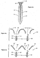
- Figures 3A and 3B schematics for some of the design variations that may be used for film generators 14, 32, 34, 36 are provided.
- film generator 100 uses half pipes 102 which are separated by distance d 1 to form gaps 104.
- the subsequent film support structures 106 are separated by horizontal distance d 2 and are positioned to be aligned with the center of gaps 104.
- film support structures 106 are a vertical distance d 3 below the bottom of film generators 100.
- the alignment of the center of the gaps 104 with the subsequent film support structures 106 ensures that both sides 112, 114 are coated with polymer melt 46.
- film generator 120 includes equal leg angles for the film generator 122 which are separated by distance d 4 to form gaps 124.
- the subsequent film support structures 126 are separated by horizontal distance d 5 and are positioned to align with gaps 124.
- film support structures 126 are a vertical distance d 6 below the bottom of film generators 120. Again, the alignment of gaps 124 and film support structures 126 ensures that both sides 132, 134 are coated with polymer melt 46.
- distances d 1 and d 4 will be from about 0.25 (corresponding to about 6.35 mm) to about 2 inches (corresponding to about 50.8 mm) distances and d 5 will be from about 0.5 (corresponding to about 12.7 mm) to about 10 inches (corresponding to about 254 mm), and distances d 3 and d 6 will be from about 0 to about 2 inches (corresponding to about 50.8 mm).
- distances d 2 and d 5 will be from about 0.75 (corresponding to about 19.05 mm) to about 3 inches (corresponding to about 76.2 mm).
- the film support structure alternatively can pass completely through the gaps 104, 124.
- the configuration of the film generator can be adapted to feed a single stream to both sides of the film support structure, or to feed two separate streams, one flowing to each side of the film support structure.
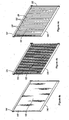
- Figure 4A provides a perspective view of a framed solid flat plate used in one variation for the film support structures 38-44.
- film support structure 140 includes solid plate section 142 and frame sections 144, 146.
- Frame sections 144, 146 assist in the placement of the framed film support structures into a support rack and add mechanical strength to maintain the shape and position of the film support structure.
- Figure 4B provides a perspective view of a foraminous film support structure that comprises a framed mesh that may be used in a variation of film support structures 38-44.
- film support structure 150 includes mesh section 152 and frame sections 154, 156. Any mesh style may be used for mesh section 152 (i.e., wire cloth or fabric, meshed screening, perforated metal or expanded metal sheet). Typically, the openings in the foraminous film support structure will range from 0.25 (corresponding to about 6.35 mm) to 3 inches (corresponding to about 76.2 mm).
- Figure 4C provides a perspective view of a framed set of substantially vertical wires that may be used in another variation of film support structures 38-44.
- film support structure 160 includes wire film support structure section 162 and frame sections 164, 166. Wire film support structure section 162 is formed by a set of substantially coplanar and substantially parallel wires 168.
- Wire diameters typically are from about 0.010 (corresponding to about 0.254 mm) to about 0.125 inches (corresponding to about 3.175 mm) with spacing between the wires from about 0.25 (corresponding to about 6.35 mm) to about 2.0 inches (corresponding to about 50.8 mm).
- wires are referred to, rods or tubes can be used as well, and, a circular cross-section is not a necessity.
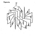
- FIG. 5A provides a perspective view demonstrating the use of planar film support structures 180 arranged about a vertical line using equal angular spacing between adjacent film support structures.
- Figure 5B provides a perspective view of film generator 182 placed over the angularly displaced film support structures of Figure 5A .
- Film generator 182 includes an array of openings 184 positioned to introduce polymer melt onto the surfaces of the planar film support structures.
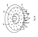
- Figure 6A provides a perspective view demonstrating the use of film support structures in the form of concentric cylinders 190, 192, 194.
- Figure 6B provides a perspective view of film generator 196 placed over the concentric cylinders of Figure 6A .
- Film generator 196 includes an array of openings 198 positioned to introduce polymer melt onto the cylindrical film support structures.
- Figure 6C provides a perspective view of a spiraling film support structure 200
- Figure 6D provides a perspective view of film generator 202 positioned over the spiraling film support structure 200.
- film generator 202 includes an array of openings 204 positioned to introduce polymer melt onto the surface of the spiraling film support structure 200. It should also be appreciated that discontinuities or gaps in the film support structures of Figures 6A-D are also contemplated as being within the scope of the invention.
- FIG. 7A , 7B, and 7C perspective views of a support rack 210 holding some of the various planar film support structures described in the present invention are provided.
- Figure 7A illustrates a support rack 210 holding framed solid flat plate film support structures 140.
- Figure 7B illustrates a support rack 210 holding framed mesh film support structures 150.
- Figure 7C illustrates a support rack 210 holding framed wire film support structures 162.
- the support rack 210 can hold any desired combination of framed solid plate film support structures 140, framed mesh film support structures 150, and framed wire film support structures 162. In the typical application, rack 210 will hold only one type of film support structure.
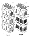
- Figure 8A is a perspective view illustrating a bundle with each support rack holding a row of the same type of film support structures.
- Bundle 212 includes inlet film generator 214.
- Inlet film generator 214 is positioned above rack 210 that holds an array of film support structures 216.
- Rack 210 is positioned above intermediate film generator 218 that includes the film generators set forth above.
- Intermediate film generator 218 is positioned above rack 220 that holds a second array of film support structures 216.
- rack 220 is positioned above intermediate film generator 222 that is in turn positioned above rack 224.
- rack 224 is positioned above rack 224.
- the present example provides a bundle assembly with three racks, it should be appreciated that an arbitrary number of support racks may be utilized.
- this example utilizes a set of film support structures 216 which are all solid plate of the same type, combinations of different types of film support structures (i.e., solid, mesh, or wire) can be used.
- Figure 8B is a perspective view illustrating a bundle with each rack (row) of film support structures utilizing a different type of film support structure.
- the bundle 230 includes inlet film generator 214.
- Inlet film generator 214 is positioned above rack 210 that holds an array of film support structures 232.
- Film support structures 232 are framed solid flat plate film support structures.
- Rack 210 is positioned above intermediate film generator 238 that includes the film generators set forth above.
- Intermediate film generator 238 is positioned above rack 240 which holds a second array of film support structures 242.
- Film support structures 242 are framed mesh film support structures.
- rack 240 is positioned above intermediate film generator 248 that is in turn positioned above rack 244.
- Rack 244 hold a third array of film support structures 246 which are framed wire film support structures.
- the horizontal spacing within a row of film support structures can be adapted to the melt viscosity of the liquid (i.e., polymer melt).
- the viscosity increases from the top to the bottom of the reactor, the minimum horizontal spacing increases between the adjacent film support structures.
- the number of film support structures in a row decreases.
- Intermediate film generators also facilitate changing the orientation of the film support structures, for example, having the film support structures in successive rows rotated 90 degrees about the reactor centerline.
- polymerization reactor 250 includes bundle assembly 10 and vertically disposed containment 252.
- Polymeric melt inlet 254 is attached near the top 256 of vertically disposed containment 252 and polymeric melt outlet 258 is attached near the bottom 260 of outer shell 252.
- polymerization reactor 250 also includes vapor outlet 262 attached to outer shell 252.
- the polymerization reactor 250 includes bundle assembly 10 that receives the polymeric melt from polymeric melt inlet and transfers the polymeric melt to the polymeric melt outlet, as set forth above.
- Polymerization reactor 250 also includes a heater (not shown) for maintaining polymer melt in a fluid state and a vacuum pump (not shown) for reducing the pressure inside the polymerization reactor.
- the vacuum pump will typically act through vapor outlet 262.
- the bundle assembly 10 includes arrays of film support structures 272, 274, 276 and film generators 278, 280 and 282.
- film support structures may be placed side by side in addition to or in place of the stacked arrangement illustrated in Figure 9 for film support structures 272, 274, 276.
- the operation of the bundle assembly is the same as that set forth above.
- the film support structures are mounted in the vessel to provide retention of the polymer melts, thereby increasing liquid residence time within the reactor and its exposure to the reaction conditions.
- the liquid residence time is required to allow sufficient time for the polymerization kinetics to keep up with the enhanced byproduct liberation rates achieved by the increase in the liquid-vapor surface area and the enhancement of its renewal. Not only does this design provide more free surface area for vapor to leave the polymer, but it also provides more parallel flow paths so that the thickness of the films are reduced when compared to the prior art such as roof-and-trough trays.
- a method of increasing the degree of polymerization in a polymeric melt using the bundle assembly set forth above comprises introducing the polymeric melt into a bundle assembly at a sufficient temperature and pressure.
- the details of the bundle assembly are set forth above.
- the method of this embodiment comprises contacting the highest film generator and then the highest positioned row of film support structures with the polymeric melt.
- the optional intermediate film generators and rows of film support structures are contacted with the polymeric melt.
- the lowest positioned row of film support structures is contacted with the polymeric melt. After passing over the lowest positioned row of film support structures, the polymeric melt falls from the bundle assembly.
- the polymeric melt removed from the bundle assembly advantageously has a higher degree of polymerization than when the polymeric melt was introduced into the bundle assembly.
- the reaction temperature is from about 250° C to about 320° C and the reaction pressure is from about 0.2 torr (corresponding to about 26.7 Pa) to about 30 torr (corresponding to about 4 kPa).
Landscapes
- Chemical & Material Sciences (AREA)
- Organic Chemistry (AREA)
- Chemical Kinetics & Catalysis (AREA)
- Thermal Sciences (AREA)
- Physics & Mathematics (AREA)
- Medicinal Chemistry (AREA)
- Polymers & Plastics (AREA)
- Health & Medical Sciences (AREA)
- Polyesters Or Polycarbonates (AREA)
- Polymerisation Methods In General (AREA)
- Separation Using Semi-Permeable Membranes (AREA)
- Other Resins Obtained By Reactions Not Involving Carbon-To-Carbon Unsaturated Bonds (AREA)
- Physical Or Chemical Processes And Apparatus (AREA)
Claims (20)
- Vertikal angeordneter Polymerisationsreaktor (250) zum Polymerisieren einer Polymerschmelze, mit einer Bündelanordnung (10) von Einbauten, wobei die Bündelanordung (10) umfasst:- eine erste stationäre Anordnung (24) einer oder mehrerer Filmtragstrukturen (38; 106; 126; 140, 150, 160; 162; 180; 190, 192, 194; 200; 216; 232; 242; 246; 272, 274, 276), die ausgerichtet sind zur Ausbildung aufeinanderfolgender, horizontal beabstandeter Flächen mit durchgängigem Abstand, wobei jede Filmtragstruktur bezüglich der horizontalen Ebene unter einem Winkel von etwa 60 Grad oder mehr angeordnet ist, und wobei jede Filmtragstruktur eine erste Seite (76) und eine zweite Seite (80) aufweist,- eine oder mehrere zusätzliche stationäre Anordnungen (24) einer oder mehrerer Filmtragstrukturen, wobei die zusätzlichen stationären Anordnungen jeweils in einer oder mehreren zusätzlichen vertikalen Reihen angeordnet sind, wobei jede Reihe horizontal beabstandete, auf gleicher Höhe angeordnete Filmtragstrukturen aufweist, wobei die zusätzlichen Anordnungen eine unterste stationäre Anordnung umfassen, derart, dass die Bündelanordnung ein Fließen der Polymerschmelze von der ersten stationären Anordnung zur untersten stationären Anordnung zu ermöglichen vermag, und- einen oder mehrere stationäre Filmgeber (14, 32, 34, 36; 100; 102; 120; 122; 182; 196; 202; 214, 218, 222, 238, 248; 278, 280, 282), die oberhalb einer zugehörigen, stationären Anordnung der stationären Anordnungen einer oder mehrerer Filmtragstrukturen angeordnet sind,wobei- das Fließen der Polymerschmelze (46) innerhalb des Reaktors (250) gravitationsgetrieben ist,- der eine oder die mehreren Filmgeber vollständig oberhalb der zugehörigen Anordnung der einen oder mehreren Filmtragstrukturen angeordnet sind,- der eine oder die mehreren Filmgeber die Polymerschmelze (46) unterteilen und auf die eine oder die mehreren Filmtragstrukturen richten durch zumindest eine Öffnung (104; 124; 184; 198; 204), die oberhalb und in Ausrichtung mit einer nachfolgenden Filmtragstruktur angeordnet ist, so dass dann, wenn eine Polymerschmelze (46) durch die zumindest eine Öffnung (104; 124; 184; 198; 204) fließt, ein erster Anteil (74) der unterteilten Polymerschmelze zum Fließen über die erste Seite (76) der nachfolgenden Filmtragstruktur geleitet wird und ein zweiter Anteil (78) der unterteilten Polymerschmelze zum Fließen über die zweite Seite (80) der nachfolgenden Filmtragstruktur geleitet wird.
- Reaktor nach Anspruch 1, bei dem die Flächen im Wesentlichen parallel sind.
- Reaktor nach Anspruch 1, bei dem jede Filmtragstruktur bezüglich der horizontalen Ebene unter einem Winkel größer als etwa 80 Grad angeordnet ist, wobei die Anordnung der Filmtragstrukturen zur Ausbildung einer oder mehrerer Reihen angeordnet ist und jede Reihe horizontal beabstandete, auf gleicher Höhe angeordnete Filmtragstrukturen aufweist.
- Reaktor nach Anspruch 1, bei dem jede Filmtragstruktur der Filmtragstrukturenanordnung eine massive Platte aufweist.
- Reaktor nach Anspruch 1, bei dem jede Filmtragstruktur der Filmtragstrukturenanordnung eine Filmtragstruktur mit Durchgangsöffnungen aufweist.
- Reaktor nach Anspruch 5, bei dem jede Filmtragstruktur mit Durchgangsöffnungen der Filmtragstrukturenanordnung ein Drahtgewebe oder eine Drahtstruktur, ein Siebnetz, ein perforiertes Metall oder ein Streckblech umfasst.
- Reaktor nach Anspruch 6, bei dem die Filmtragstruktur mit Durchgangsöffnungen Öffnungen von etwa 0,25 Zoll (entsprechend etwa 6,35 mm) bis etwa 3 Zoll (entsprechend etwa 76,2 mm) aufweist.
- Reaktor nach Anspruch 1, bei dem jede Filmtragstruktur der Filmtragstrukturenanordnung einen Satz von im Wesentlichen vertikalen und im Wesentlichen parallelen Drähten, Stäben oder Röhren umfasst.
- Reaktor nach Anspruch 1, bei dem der horizontale Abstand zwischen benachbarten Filmtragstrukturen der Filmtragstrukturenanordnung so ist, dass wenn die Polymerschmelze in einem stationären Betriebszustand durch die Bündelanordnung fließt, jeder der unterteilten und unabhängigen Polymerschmelzströme eine Dicke von zumindest 10% des Abstands zwischen jeder Filmtragstruktur hat.
- Reaktor nach Anspruch 1, bei dem jede Filmtragstruktur der Filmtragstrukturenanordnung von einer horizontal benachbarten Filmtragstruktur durch einen Abstand von etwa 0,5 Zoll (entsprechend etwa 12,7 mm) bis etwa 10 Zoll (entsprechend etwa 254 mm) getrennt ist.
- Reaktor nach Anspruch 1, bei dem der Filmgeber der Polymerschmelze für jede die Filmtragstrukturenanordnung ausbildende Filmtragstruktur unmittelbar unterhalb des Filmgebers einen oder mehrere Polymerströme erzeugt.
- Reaktor nach Anspruch 1, bei dem die eine oder die mehreren Filmtragstrukturen eine Komponente umfassen, die ausgewählt ist aus der Gruppe bestehend aus zylindrischen Strukturen, spiralförmigen Strukturen oder Strukturen mit im Wesentlichen vertikalen, jedoch nicht parallelen Flächen.
- Verfahren zum Erhöhen eines Polymerisationsgrads in einer Polymerschmelze (46), wobei das Verfahren umfasst:a) Einbringen der Polymerschmelze (46) in die Bündelanordnung (10) des Reaktors (250) nach Anspruch 1 bei einer hinreichenden Temperatur und hinreichendem Druck zur Polymerisation der Polymerschmelze (46);b) Aussetzen der resultierenden freien Oberflächen (74, 78) der Polymerschmelze der Atmosphäre des Reaktors (52); undc) Entnehmen der Polymerschmelze aus der Bündelanordnung (10), wobei die aus der Bündelanordnung (10) entnommene Polymerschmelze einen höheren Polymerisationsgrad aufweist als die Polymerschmelze (46) beim Einbringen in die Bündelanordnung (10).
- Verfahren nach Anspruch 13, bei dem die Temperatur im Bereich von etwa 250 °C bis etwa 320 °C liegt.
- Verfahren nach Anspruch 13, bei dem der Druck im Bereich von etwa 0,2 Torr (entsprechend etwa 26,7 Pa) bis etwa 30 Torr (entsprechend etwa 4 kPa) liegt.
- Verfahren nach Anspruch 13, bei dem jede Filmtragstruktur einer Filmtragstrukturenanordnung eine massive Platte aufweist.
- Verfahren nach Anspruch 13, bei dem jede Filmtragstruktur einer Filmtragstrukturenanordnung eine Filmtragstruktur mit Durchgangsöffnungen umfasst.
- Verfahren nach Anspruch 17, bei dem jede Filmtragstruktur mit Durchgangsöffnungen einer Filmtragstrukturenanordnung ein Drahtgewebe oder eine Drahtstruktur, ein Siebnetz, ein perforiertes Metall oder ein Streckblech umfasst.
- Verfahren nach Anspruch 18, bei dem die Filmtragstruktur mit Durchgangsöffnungen Öffnungen von etwa 0,25 Zoll (entsprechend etwa 6,35 mm) bis etwa 3 Zoll (entsprechend etwa 76,2 mm) aufweist.
- Verfahren nach Anspruch 13, bei dem jede Filmtragstruktur einer Filmtragstrukturenanordnung einen Satz von im Wesentlichen vertikalen und im Wesentlichen parallelen Drähten, Stäben oder Röhren umfasst.
Priority Applications (1)
| Application Number | Priority Date | Filing Date | Title |
|---|---|---|---|
| PL06751467T PL1901840T3 (pl) | 2005-05-05 | 2006-04-25 | Pionowy członowy reaktor polimeryzacyjny |
Applications Claiming Priority (2)
| Application Number | Priority Date | Filing Date | Title |
|---|---|---|---|
| US11/122,965 US20060251547A1 (en) | 2005-05-05 | 2005-05-05 | Family of stationary film generators and film support structures for vertical staged polymerization reactors |
| PCT/US2006/015770 WO2006121615A1 (en) | 2005-05-05 | 2006-04-25 | A family of stationary film generators and film support structures for vertical staged polymerization reactors |
Publications (2)
| Publication Number | Publication Date |
|---|---|
| EP1901840A1 EP1901840A1 (de) | 2008-03-26 |
| EP1901840B1 true EP1901840B1 (de) | 2014-05-14 |
Family
ID=36822308
Family Applications (1)
| Application Number | Title | Priority Date | Filing Date |
|---|---|---|---|
| EP06751467.9A Active EP1901840B1 (de) | 2005-05-05 | 2006-04-25 | Vertikal gestufter polymerisationsreaktor |
Country Status (15)
| Country | Link |
|---|---|
| US (1) | US20060251547A1 (de) |
| EP (1) | EP1901840B1 (de) |
| JP (2) | JP2008540734A (de) |
| KR (1) | KR101354266B1 (de) |
| CN (1) | CN101247887B (de) |
| AR (1) | AR056989A1 (de) |
| BR (1) | BRPI0611132A2 (de) |
| CA (1) | CA2606055A1 (de) |
| ES (1) | ES2469671T3 (de) |
| MX (1) | MX2007013586A (de) |
| MY (1) | MY153271A (de) |
| PL (1) | PL1901840T3 (de) |
| RU (1) | RU2403970C2 (de) |
| TW (1) | TWI415672B (de) |
| WO (1) | WO2006121615A1 (de) |
Families Citing this family (18)
| Publication number | Priority date | Publication date | Assignee | Title |
|---|---|---|---|---|
| US6906164B2 (en) | 2000-12-07 | 2005-06-14 | Eastman Chemical Company | Polyester process using a pipe reactor |
| US7435393B2 (en) * | 2005-05-05 | 2008-10-14 | Eastman Chemical Company | Baffle assembly module for vertical staged polymerization reactors |
| US7649109B2 (en) | 2006-12-07 | 2010-01-19 | Eastman Chemical Company | Polyester production system employing recirculation of hot alcohol to esterification zone |
| US7943094B2 (en) | 2006-12-07 | 2011-05-17 | Grupo Petrotemex, S.A. De C.V. | Polyester production system employing horizontally elongated esterification vessel |
| US7863477B2 (en) | 2007-03-08 | 2011-01-04 | Eastman Chemical Company | Polyester production system employing hot paste to esterification zone |
| US7892498B2 (en) * | 2007-03-08 | 2011-02-22 | Eastman Chemical Company | Polyester production system employing an unagitated esterification reactor |
| US7829653B2 (en) | 2007-07-12 | 2010-11-09 | Eastman Chemical Company | Horizontal trayed reactor |
| US7842777B2 (en) * | 2007-07-12 | 2010-11-30 | Eastman Chemical Company | Sloped tubular reactor with divided flow |
| US7847053B2 (en) | 2007-07-12 | 2010-12-07 | Eastman Chemical Company | Multi-level tubular reactor with oppositely extending segments |
| US7872089B2 (en) | 2007-07-12 | 2011-01-18 | Eastman Chemical Company | Multi-level tubular reactor with internal tray |
| US7858730B2 (en) | 2007-07-12 | 2010-12-28 | Eastman Chemical Company | Multi-level tubular reactor with dual headers |
| US7868130B2 (en) | 2007-07-12 | 2011-01-11 | Eastman Chemical Company | Multi-level tubular reactor with vertically spaced segments |
| US7868129B2 (en) | 2007-07-12 | 2011-01-11 | Eastman Chemical Company | Sloped tubular reactor with spaced sequential trays |
| US7872090B2 (en) | 2007-07-12 | 2011-01-18 | Eastman Chemical Company | Reactor system with optimized heating and phase separation |
| EA024379B1 (ru) * | 2010-10-29 | 2016-09-30 | Асахи Касеи Кемикалз Корпорейшн | Способ получения ароматического поликарбоната реакцией поликонденсации и реактор полимеризации |
| US11286436B2 (en) | 2019-02-04 | 2022-03-29 | Eastman Chemical Company | Feed location for gasification of plastics and solid fossil fuels |
| US11447576B2 (en) | 2019-02-04 | 2022-09-20 | Eastman Chemical Company | Cellulose ester compositions derived from recycled plastic content syngas |
| CN117980444A (zh) | 2021-09-21 | 2024-05-03 | 伊士曼化工公司 | 热解流出物与液化塑料在化学设施中的直接接触 |
Family Cites Families (23)
| Publication number | Priority date | Publication date | Assignee | Title |
|---|---|---|---|---|
| US2645607A (en) * | 1948-10-30 | 1953-07-14 | Us Hoffman Machinery Corp | Vaporizer unit and tray |
| US2753594A (en) * | 1952-05-03 | 1956-07-10 | Inventa Ag | Apparatus for use in the melt-spinning of synthetic polymers |
| BE570443A (de) * | 1957-09-28 | |||
| US3150211A (en) * | 1961-05-09 | 1964-09-22 | British Columbia Res Council | Gas-liquid contacting apparatus |
| US3250747A (en) * | 1961-12-07 | 1966-05-10 | Eastman Kodak Co | Polyesterification in two evacuated zones separated by a liquid seal |
| US3316064A (en) * | 1964-04-30 | 1967-04-25 | Hitachi Ltd | Apparatus for continuous polycondensation reaction |
| DE2041122A1 (de) | 1970-08-19 | 1972-03-02 | Metallgesellschaft Ag | Vorrichtung und Verfahren zur Durchfuehrung organisch-chemischer Reaktionen |
| DD98691A1 (de) | 1971-09-10 | 1973-07-12 | ||
| US3841836A (en) * | 1972-08-10 | 1974-10-15 | Eastman Kodak Co | Apparatus for the production of condensation polymers |
| US4145520A (en) * | 1974-10-09 | 1979-03-20 | Bayer Aktiengesellschaft | Process for the continuous polymerization of lactams with static mixers |
| IT1097584B (it) * | 1977-08-24 | 1985-08-31 | Basf Ag | Processo ed apparecchio per la preparazione di poliesteri macronolecolari linerai |
| US4196168A (en) * | 1978-05-05 | 1980-04-01 | Eastman Kodak Company | Sloped tray arrangement for polymerization reactor |
| JPH0533801U (ja) * | 1991-10-02 | 1993-05-07 | 住友重機械工業株式会社 | プレ−ト式蒸発缶におけるヒ−テイングエレメントへの処理液分散装置 |
| DK0803277T3 (da) * | 1993-01-13 | 2002-06-17 | Kansai Electric Power Co | Apparat til gas-væskekontakt |
| US5464590A (en) * | 1994-05-02 | 1995-11-07 | Yount; Thomas L. | Reactor trays for a vertical staged polycondensation reactor |
| US5466419A (en) * | 1994-05-02 | 1995-11-14 | Yount; Thomas L. | Split flow reactor trays for vertical staged polycondensation reactors |
| JP3569063B2 (ja) * | 1995-03-24 | 2004-09-22 | 旭化成ケミカルズ株式会社 | 芳香族ポリカーボネートの製造法 |
| MY117361A (en) | 1996-03-05 | 2004-06-30 | Asahi Chemical Ind | Polycarbonate having heterounits and method for producing the same |
| AU1890499A (en) * | 1998-01-14 | 1999-08-02 | Asahi Kasei Kogyo Kabushiki Kaisha | Process and polymerizer for producing aromatic polycarbonate |
| JP4739523B2 (ja) | 1998-06-16 | 2011-08-03 | 旭化成ケミカルズ株式会社 | 重縮合ポリマーを製造する方法 |
| US6761797B2 (en) | 2000-12-27 | 2004-07-13 | Bayer Aktiengesellschaft | Apparatus for carrying out mass transfer processes |
| KR100713038B1 (ko) | 2003-10-10 | 2007-05-04 | 아사히 가세이 케미칼즈 가부시키가이샤 | 폴리알킬렌 테레프탈레이트의 제조 방법, 폴리알킬렌테레프탈레이트 성형체의 제조 방법 및 폴리알킬렌테레프탈레이트 성형체 |
| CN1228119C (zh) * | 2003-11-06 | 2005-11-23 | 刘兆彦 | 一种栅缝降膜脱挥塔 |
-
2005
- 2005-05-05 US US11/122,965 patent/US20060251547A1/en not_active Abandoned
-
2006
- 2006-04-10 MY MYPI20061625A patent/MY153271A/en unknown
- 2006-04-25 KR KR1020077025376A patent/KR101354266B1/ko active IP Right Grant
- 2006-04-25 MX MX2007013586A patent/MX2007013586A/es active IP Right Grant
- 2006-04-25 PL PL06751467T patent/PL1901840T3/pl unknown
- 2006-04-25 RU RU2007145056/05A patent/RU2403970C2/ru not_active IP Right Cessation
- 2006-04-25 WO PCT/US2006/015770 patent/WO2006121615A1/en active Application Filing
- 2006-04-25 CN CN2006800153621A patent/CN101247887B/zh not_active Expired - Fee Related
- 2006-04-25 ES ES06751467.9T patent/ES2469671T3/es active Active
- 2006-04-25 EP EP06751467.9A patent/EP1901840B1/de active Active
- 2006-04-25 JP JP2008510048A patent/JP2008540734A/ja not_active Withdrawn
- 2006-04-25 BR BRPI0611132-7A patent/BRPI0611132A2/pt not_active IP Right Cessation
- 2006-04-25 CA CA002606055A patent/CA2606055A1/en not_active Abandoned
- 2006-04-26 AR ARP060101663A patent/AR056989A1/es active IP Right Grant
- 2006-05-04 TW TW095115834A patent/TWI415672B/zh not_active IP Right Cessation
-
2013
- 2013-08-19 JP JP2013169702A patent/JP5798161B2/ja not_active Expired - Fee Related
Also Published As
| Publication number | Publication date |
|---|---|
| MY153271A (en) | 2015-01-29 |
| RU2007145056A (ru) | 2009-06-10 |
| BRPI0611132A2 (pt) | 2010-11-09 |
| MX2007013586A (es) | 2008-01-14 |
| JP5798161B2 (ja) | 2015-10-21 |
| PL1901840T3 (pl) | 2014-09-30 |
| AR056989A1 (es) | 2007-11-07 |
| JP2008540734A (ja) | 2008-11-20 |
| US20060251547A1 (en) | 2006-11-09 |
| WO2006121615A1 (en) | 2006-11-16 |
| CN101247887B (zh) | 2011-11-30 |
| CN101247887A (zh) | 2008-08-20 |
| TW200704433A (en) | 2007-02-01 |
| CA2606055A1 (en) | 2006-11-16 |
| ES2469671T3 (es) | 2014-06-18 |
| JP2013231201A (ja) | 2013-11-14 |
| TWI415672B (zh) | 2013-11-21 |
| KR101354266B1 (ko) | 2014-01-22 |
| EP1901840A1 (de) | 2008-03-26 |
| RU2403970C2 (ru) | 2010-11-20 |
| KR20080009096A (ko) | 2008-01-24 |
Similar Documents
| Publication | Publication Date | Title |
|---|---|---|
| EP1901840B1 (de) | Vertikal gestufter polymerisationsreaktor | |
| EP1879692B1 (de) | Einbautenanordnungsmodul für vertikal gestufte polymerisationsreaktoren | |
| US7959133B2 (en) | Grid falling film devolatilizer | |
| JP2007509751A5 (de) | ||
| KR100962873B1 (ko) | 폴리에스테르의 연속 제조를 위한 방법 및 장치 | |
| CN102451660A (zh) | 一种下流式预聚塔 | |
| CN113717355B (zh) | 一种连续制备聚乙交酯和丙交酯嵌段共聚物的方法和装置 | |
| CN1089270C (zh) | 一种栅板式聚酯缩聚塔 | |
| KR20070012403A (ko) | 폴리에스테르 제조 방법 | |
| CN216172365U (zh) | 一种用于连续合成plga共聚物的系统 | |
| KR101337202B1 (ko) | 다발관 강하막 반응기 및 이를 이용한 젖산 고분자 제조방법 | |
| BRPI0611132B1 (pt) | A polymerizer reacter vertically provided for polymerization of a polymer fused paste, and, a method for increasing the polymerization degree in a polymer fused paste |
Legal Events
| Date | Code | Title | Description |
|---|---|---|---|
| PUAI | Public reference made under article 153(3) epc to a published international application that has entered the european phase |
Free format text: ORIGINAL CODE: 0009012 |
|
| 17P | Request for examination filed |
Effective date: 20071026 |
|
| AK | Designated contracting states |
Kind code of ref document: A1 Designated state(s): AT BE BG CH CY CZ DE DK EE ES FI FR GB GR HU IE IS IT LI LT LU LV MC NL PL PT RO SE SI SK TR |
|
| RIN1 | Information on inventor provided before grant (corrected) |
Inventor name: YOUNT, THOMAS LLOYD Inventor name: SLAUGHTER, CHRISTOPHER SCOTT Inventor name: SCHERRER, PAUL KEITH Inventor name: BONNER, RICHARD GILL Inventor name: WINDES, LARRY CATES Inventor name: MURDOCH, WILLIAM SPEIGHT |
|
| 17Q | First examination report despatched |
Effective date: 20080418 |
|
| DAX | Request for extension of the european patent (deleted) | ||
| GRAJ | Information related to disapproval of communication of intention to grant by the applicant or resumption of examination proceedings by the epo deleted |
Free format text: ORIGINAL CODE: EPIDOSDIGR1 |
|
| GRAP | Despatch of communication of intention to grant a patent |
Free format text: ORIGINAL CODE: EPIDOSNIGR1 |
|
| GRAP | Despatch of communication of intention to grant a patent |
Free format text: ORIGINAL CODE: EPIDOSNIGR1 |
|
| INTG | Intention to grant announced |
Effective date: 20131011 |
|
| RAP1 | Party data changed (applicant data changed or rights of an application transferred) |
Owner name: EASTMAN CHEMICAL COMPANY |
|
| RIN1 | Information on inventor provided before grant (corrected) |
Inventor name: SCHERRER, PAUL KEITH Inventor name: WINDES, LARRY CATES Inventor name: YOUNT, THOMAS LLOYD Inventor name: MURDOCH, WILLIAM SPEIGHT Inventor name: SLAUGHTER, CHRISTOPHER SCOTT Inventor name: BONNER, RICHARD GILL |
|
| GRAS | Grant fee paid |
Free format text: ORIGINAL CODE: EPIDOSNIGR3 |
|
| GRAP | Despatch of communication of intention to grant a patent |
Free format text: ORIGINAL CODE: EPIDOSNIGR1 |
|
| GRAA | (expected) grant |
Free format text: ORIGINAL CODE: 0009210 |
|
| INTG | Intention to grant announced |
Effective date: 20140319 |
|
| AK | Designated contracting states |
Kind code of ref document: B1 Designated state(s): AT BE BG CH CY CZ DE DK EE ES FI FR GB GR HU IE IS IT LI LT LU LV MC NL PL PT RO SE SI SK TR |
|
| REG | Reference to a national code |
Ref country code: GB Ref legal event code: FG4D |
|
| REG | Reference to a national code |
Ref country code: CH Ref legal event code: NV Representative=s name: KIRKER AND CIE S.A., CH |
|
| REG | Reference to a national code |
Ref country code: AT Ref legal event code: REF Ref document number: 667826 Country of ref document: AT Kind code of ref document: T Effective date: 20140615 |
|
| REG | Reference to a national code |
Ref country code: IE Ref legal event code: FG4D Ref country code: ES Ref legal event code: FG2A Ref document number: 2469671 Country of ref document: ES Kind code of ref document: T3 Effective date: 20140618 |
|
| REG | Reference to a national code |
Ref country code: DE Ref legal event code: R096 Ref document number: 602006041582 Country of ref document: DE Effective date: 20140703 |
|
| REG | Reference to a national code |
Ref country code: NL Ref legal event code: T3 |
|
| REG | Reference to a national code |
Ref country code: PL Ref legal event code: T3 |
|
| REG | Reference to a national code |
Ref country code: AT Ref legal event code: MK05 Ref document number: 667826 Country of ref document: AT Kind code of ref document: T Effective date: 20140514 |
|
| PG25 | Lapsed in a contracting state [announced via postgrant information from national office to epo] |
Ref country code: IS Free format text: LAPSE BECAUSE OF FAILURE TO SUBMIT A TRANSLATION OF THE DESCRIPTION OR TO PAY THE FEE WITHIN THE PRESCRIBED TIME-LIMIT Effective date: 20140914 Ref country code: GR Free format text: LAPSE BECAUSE OF FAILURE TO SUBMIT A TRANSLATION OF THE DESCRIPTION OR TO PAY THE FEE WITHIN THE PRESCRIBED TIME-LIMIT Effective date: 20140815 Ref country code: FI Free format text: LAPSE BECAUSE OF FAILURE TO SUBMIT A TRANSLATION OF THE DESCRIPTION OR TO PAY THE FEE WITHIN THE PRESCRIBED TIME-LIMIT Effective date: 20140514 Ref country code: CY Free format text: LAPSE BECAUSE OF FAILURE TO SUBMIT A TRANSLATION OF THE DESCRIPTION OR TO PAY THE FEE WITHIN THE PRESCRIBED TIME-LIMIT Effective date: 20140514 |
|
| PG25 | Lapsed in a contracting state [announced via postgrant information from national office to epo] |
Ref country code: LV Free format text: LAPSE BECAUSE OF FAILURE TO SUBMIT A TRANSLATION OF THE DESCRIPTION OR TO PAY THE FEE WITHIN THE PRESCRIBED TIME-LIMIT Effective date: 20140514 Ref country code: AT Free format text: LAPSE BECAUSE OF FAILURE TO SUBMIT A TRANSLATION OF THE DESCRIPTION OR TO PAY THE FEE WITHIN THE PRESCRIBED TIME-LIMIT Effective date: 20140514 Ref country code: SE Free format text: LAPSE BECAUSE OF FAILURE TO SUBMIT A TRANSLATION OF THE DESCRIPTION OR TO PAY THE FEE WITHIN THE PRESCRIBED TIME-LIMIT Effective date: 20140514 |
|
| PG25 | Lapsed in a contracting state [announced via postgrant information from national office to epo] |
Ref country code: PT Free format text: LAPSE BECAUSE OF FAILURE TO SUBMIT A TRANSLATION OF THE DESCRIPTION OR TO PAY THE FEE WITHIN THE PRESCRIBED TIME-LIMIT Effective date: 20140915 |
|
| PG25 | Lapsed in a contracting state [announced via postgrant information from national office to epo] |
Ref country code: EE Free format text: LAPSE BECAUSE OF FAILURE TO SUBMIT A TRANSLATION OF THE DESCRIPTION OR TO PAY THE FEE WITHIN THE PRESCRIBED TIME-LIMIT Effective date: 20140514 Ref country code: RO Free format text: LAPSE BECAUSE OF FAILURE TO SUBMIT A TRANSLATION OF THE DESCRIPTION OR TO PAY THE FEE WITHIN THE PRESCRIBED TIME-LIMIT Effective date: 20140514 Ref country code: CZ Free format text: LAPSE BECAUSE OF FAILURE TO SUBMIT A TRANSLATION OF THE DESCRIPTION OR TO PAY THE FEE WITHIN THE PRESCRIBED TIME-LIMIT Effective date: 20140514 Ref country code: SK Free format text: LAPSE BECAUSE OF FAILURE TO SUBMIT A TRANSLATION OF THE DESCRIPTION OR TO PAY THE FEE WITHIN THE PRESCRIBED TIME-LIMIT Effective date: 20140514 Ref country code: BE Free format text: LAPSE BECAUSE OF FAILURE TO SUBMIT A TRANSLATION OF THE DESCRIPTION OR TO PAY THE FEE WITHIN THE PRESCRIBED TIME-LIMIT Effective date: 20140514 Ref country code: DK Free format text: LAPSE BECAUSE OF FAILURE TO SUBMIT A TRANSLATION OF THE DESCRIPTION OR TO PAY THE FEE WITHIN THE PRESCRIBED TIME-LIMIT Effective date: 20140514 |
|
| REG | Reference to a national code |
Ref country code: DE Ref legal event code: R097 Ref document number: 602006041582 Country of ref document: DE |
|
| PLBE | No opposition filed within time limit |
Free format text: ORIGINAL CODE: 0009261 |
|
| STAA | Information on the status of an ep patent application or granted ep patent |
Free format text: STATUS: NO OPPOSITION FILED WITHIN TIME LIMIT |
|
| 26N | No opposition filed |
Effective date: 20150217 |
|
| REG | Reference to a national code |
Ref country code: DE Ref legal event code: R097 Ref document number: 602006041582 Country of ref document: DE Effective date: 20150217 |
|
| PG25 | Lapsed in a contracting state [announced via postgrant information from national office to epo] |
Ref country code: SI Free format text: LAPSE BECAUSE OF FAILURE TO SUBMIT A TRANSLATION OF THE DESCRIPTION OR TO PAY THE FEE WITHIN THE PRESCRIBED TIME-LIMIT Effective date: 20140514 |
|
| PG25 | Lapsed in a contracting state [announced via postgrant information from national office to epo] |
Ref country code: LU Free format text: LAPSE BECAUSE OF FAILURE TO SUBMIT A TRANSLATION OF THE DESCRIPTION OR TO PAY THE FEE WITHIN THE PRESCRIBED TIME-LIMIT Effective date: 20150425 Ref country code: MC Free format text: LAPSE BECAUSE OF FAILURE TO SUBMIT A TRANSLATION OF THE DESCRIPTION OR TO PAY THE FEE WITHIN THE PRESCRIBED TIME-LIMIT Effective date: 20140514 |
|
| REG | Reference to a national code |
Ref country code: IE Ref legal event code: MM4A |
|
| REG | Reference to a national code |
Ref country code: FR Ref legal event code: ST Effective date: 20151231 |
|
| PG25 | Lapsed in a contracting state [announced via postgrant information from national office to epo] |
Ref country code: FR Free format text: LAPSE BECAUSE OF NON-PAYMENT OF DUE FEES Effective date: 20150430 |
|
| PG25 | Lapsed in a contracting state [announced via postgrant information from national office to epo] |
Ref country code: IE Free format text: LAPSE BECAUSE OF NON-PAYMENT OF DUE FEES Effective date: 20150425 |
|
| PG25 | Lapsed in a contracting state [announced via postgrant information from national office to epo] |
Ref country code: BG Free format text: LAPSE BECAUSE OF FAILURE TO SUBMIT A TRANSLATION OF THE DESCRIPTION OR TO PAY THE FEE WITHIN THE PRESCRIBED TIME-LIMIT Effective date: 20140514 Ref country code: HU Free format text: LAPSE BECAUSE OF FAILURE TO SUBMIT A TRANSLATION OF THE DESCRIPTION OR TO PAY THE FEE WITHIN THE PRESCRIBED TIME-LIMIT; INVALID AB INITIO Effective date: 20060425 |
|
| PGFP | Annual fee paid to national office [announced via postgrant information from national office to epo] |
Ref country code: GB Payment date: 20190326 Year of fee payment: 14 Ref country code: PL Payment date: 20190327 Year of fee payment: 14 |
|
| PGFP | Annual fee paid to national office [announced via postgrant information from national office to epo] |
Ref country code: NL Payment date: 20190328 Year of fee payment: 14 |
|
| PGFP | Annual fee paid to national office [announced via postgrant information from national office to epo] |
Ref country code: DE Payment date: 20190318 Year of fee payment: 14 Ref country code: IT Payment date: 20190412 Year of fee payment: 14 Ref country code: LT Payment date: 20190409 Year of fee payment: 14 Ref country code: ES Payment date: 20190503 Year of fee payment: 14 |
|
| PGFP | Annual fee paid to national office [announced via postgrant information from national office to epo] |
Ref country code: TR Payment date: 20190410 Year of fee payment: 14 |
|
| PGFP | Annual fee paid to national office [announced via postgrant information from national office to epo] |
Ref country code: CH Payment date: 20190425 Year of fee payment: 14 |
|
| REG | Reference to a national code |
Ref country code: DE Ref legal event code: R119 Ref document number: 602006041582 Country of ref document: DE |
|
| REG | Reference to a national code |
Ref country code: CH Ref legal event code: PL |
|
| REG | Reference to a national code |
Ref country code: NL Ref legal event code: MM Effective date: 20200501 |
|
| REG | Reference to a national code |
Ref country code: LT Ref legal event code: MM4D Effective date: 20200425 |
|
| PG25 | Lapsed in a contracting state [announced via postgrant information from national office to epo] |
Ref country code: DE Free format text: LAPSE BECAUSE OF NON-PAYMENT OF DUE FEES Effective date: 20201103 Ref country code: CH Free format text: LAPSE BECAUSE OF NON-PAYMENT OF DUE FEES Effective date: 20200430 Ref country code: LI Free format text: LAPSE BECAUSE OF NON-PAYMENT OF DUE FEES Effective date: 20200430 Ref country code: LT Free format text: LAPSE BECAUSE OF NON-PAYMENT OF DUE FEES Effective date: 20200425 |
|
| GBPC | Gb: european patent ceased through non-payment of renewal fee |
Effective date: 20200425 |
|
| PG25 | Lapsed in a contracting state [announced via postgrant information from national office to epo] |
Ref country code: NL Free format text: LAPSE BECAUSE OF NON-PAYMENT OF DUE FEES Effective date: 20200501 |
|
| PG25 | Lapsed in a contracting state [announced via postgrant information from national office to epo] |
Ref country code: GB Free format text: LAPSE BECAUSE OF NON-PAYMENT OF DUE FEES Effective date: 20200425 |
|
| REG | Reference to a national code |
Ref country code: ES Ref legal event code: FD2A Effective date: 20210906 |
|
| PG25 | Lapsed in a contracting state [announced via postgrant information from national office to epo] |
Ref country code: IT Free format text: LAPSE BECAUSE OF NON-PAYMENT OF DUE FEES Effective date: 20200425 |
|
| PG25 | Lapsed in a contracting state [announced via postgrant information from national office to epo] |
Ref country code: ES Free format text: LAPSE BECAUSE OF NON-PAYMENT OF DUE FEES Effective date: 20200426 |
|
| PG25 | Lapsed in a contracting state [announced via postgrant information from national office to epo] |
Ref country code: PL Free format text: LAPSE BECAUSE OF NON-PAYMENT OF DUE FEES Effective date: 20200425 |