EP1901126B1 - Optisches Kollektorsystem - Google Patents
Optisches Kollektorsystem Download PDFInfo
- Publication number
- EP1901126B1 EP1901126B1 EP06425634A EP06425634A EP1901126B1 EP 1901126 B1 EP1901126 B1 EP 1901126B1 EP 06425634 A EP06425634 A EP 06425634A EP 06425634 A EP06425634 A EP 06425634A EP 1901126 B1 EP1901126 B1 EP 1901126B1
- Authority
- EP
- European Patent Office
- Prior art keywords
- mirror
- source
- collector
- optical
- focus
- Prior art date
- Legal status (The legal status is an assumption and is not a legal conclusion. Google has not performed a legal analysis and makes no representation as to the accuracy of the status listed.)
- Active
Links
- 230000003287 optical effect Effects 0.000 title claims abstract description 64
- 238000003384 imaging method Methods 0.000 claims abstract description 21
- 230000005855 radiation Effects 0.000 claims abstract description 21
- 238000009304 pastoral farming Methods 0.000 claims abstract description 16
- 238000001900 extreme ultraviolet lithography Methods 0.000 claims abstract description 15
- 238000001816 cooling Methods 0.000 claims description 4
- 230000003628 erosive effect Effects 0.000 claims description 2
- 230000000116 mitigating effect Effects 0.000 claims description 2
- 238000001459 lithography Methods 0.000 abstract description 2
- 238000010586 diagram Methods 0.000 description 7
- 238000002310 reflectometry Methods 0.000 description 6
- 239000011248 coating agent Substances 0.000 description 5
- 238000000576 coating method Methods 0.000 description 5
- 238000009826 distribution Methods 0.000 description 4
- KJTLSVCANCCWHF-UHFFFAOYSA-N Ruthenium Chemical compound [Ru] KJTLSVCANCCWHF-UHFFFAOYSA-N 0.000 description 3
- 238000004519 manufacturing process Methods 0.000 description 3
- 238000000034 method Methods 0.000 description 3
- 229910052707 ruthenium Inorganic materials 0.000 description 3
- 230000001678 irradiating effect Effects 0.000 description 2
- 238000001393 microlithography Methods 0.000 description 2
- 238000007665 sagging Methods 0.000 description 2
- WHXSMMKQMYFTQS-UHFFFAOYSA-N Lithium Chemical compound [Li] WHXSMMKQMYFTQS-UHFFFAOYSA-N 0.000 description 1
- XUIMIQQOPSSXEZ-UHFFFAOYSA-N Silicon Chemical compound [Si] XUIMIQQOPSSXEZ-UHFFFAOYSA-N 0.000 description 1
- ATJFFYVFTNAWJD-UHFFFAOYSA-N Tin Chemical compound [Sn] ATJFFYVFTNAWJD-UHFFFAOYSA-N 0.000 description 1
- PNEYBMLMFCGWSK-UHFFFAOYSA-N aluminium oxide Inorganic materials [O-2].[O-2].[O-2].[Al+3].[Al+3] PNEYBMLMFCGWSK-UHFFFAOYSA-N 0.000 description 1
- 230000005540 biological transmission Effects 0.000 description 1
- 239000000919 ceramic Substances 0.000 description 1
- 230000000052 comparative effect Effects 0.000 description 1
- 238000010276 construction Methods 0.000 description 1
- 230000007547 defect Effects 0.000 description 1
- 230000009977 dual effect Effects 0.000 description 1
- 230000000694 effects Effects 0.000 description 1
- 238000005323 electroforming Methods 0.000 description 1
- 238000005516 engineering process Methods 0.000 description 1
- 238000007519 figuring Methods 0.000 description 1
- 239000005357 flat glass Substances 0.000 description 1
- 230000004907 flux Effects 0.000 description 1
- 239000011521 glass Substances 0.000 description 1
- 239000002241 glass-ceramic Substances 0.000 description 1
- 238000005286 illumination Methods 0.000 description 1
- 238000010884 ion-beam technique Methods 0.000 description 1
- 229910021495 keatite Inorganic materials 0.000 description 1
- 229910052744 lithium Inorganic materials 0.000 description 1
- 239000000463 material Substances 0.000 description 1
- 238000005259 measurement Methods 0.000 description 1
- 230000002040 relaxant effect Effects 0.000 description 1
- 239000004065 semiconductor Substances 0.000 description 1
- 229910052710 silicon Inorganic materials 0.000 description 1
- 239000010703 silicon Substances 0.000 description 1
- 230000003746 surface roughness Effects 0.000 description 1
- 229910052718 tin Inorganic materials 0.000 description 1
- 229910052724 xenon Inorganic materials 0.000 description 1
- FHNFHKCVQCLJFQ-UHFFFAOYSA-N xenon atom Chemical compound [Xe] FHNFHKCVQCLJFQ-UHFFFAOYSA-N 0.000 description 1
Images


Classifications
-
- G—PHYSICS
- G03—PHOTOGRAPHY; CINEMATOGRAPHY; ANALOGOUS TECHNIQUES USING WAVES OTHER THAN OPTICAL WAVES; ELECTROGRAPHY; HOLOGRAPHY
- G03F—PHOTOMECHANICAL PRODUCTION OF TEXTURED OR PATTERNED SURFACES, e.g. FOR PRINTING, FOR PROCESSING OF SEMICONDUCTOR DEVICES; MATERIALS THEREFOR; ORIGINALS THEREFOR; APPARATUS SPECIALLY ADAPTED THEREFOR
- G03F7/00—Photomechanical, e.g. photolithographic, production of textured or patterned surfaces, e.g. printing surfaces; Materials therefor, e.g. comprising photoresists; Apparatus specially adapted therefor
- G03F7/70—Microphotolithographic exposure; Apparatus therefor
- G03F7/70058—Mask illumination systems
- G03F7/7015—Details of optical elements
- G03F7/70175—Lamphouse reflector arrangements or collector mirrors, i.e. collecting light from solid angle upstream of the light source
-
- B—PERFORMING OPERATIONS; TRANSPORTING
- B82—NANOTECHNOLOGY
- B82Y—SPECIFIC USES OR APPLICATIONS OF NANOSTRUCTURES; MEASUREMENT OR ANALYSIS OF NANOSTRUCTURES; MANUFACTURE OR TREATMENT OF NANOSTRUCTURES
- B82Y10/00—Nanotechnology for information processing, storage or transmission, e.g. quantum computing or single electron logic
-
- G—PHYSICS
- G02—OPTICS
- G02B—OPTICAL ELEMENTS, SYSTEMS OR APPARATUS
- G02B19/00—Condensers, e.g. light collectors or similar non-imaging optics
- G02B19/0004—Condensers, e.g. light collectors or similar non-imaging optics characterised by the optical means employed
- G02B19/0019—Condensers, e.g. light collectors or similar non-imaging optics characterised by the optical means employed having reflective surfaces only (e.g. louvre systems, systems with multiple planar reflectors)
-
- G—PHYSICS
- G02—OPTICS
- G02B—OPTICAL ELEMENTS, SYSTEMS OR APPARATUS
- G02B19/00—Condensers, e.g. light collectors or similar non-imaging optics
- G02B19/0033—Condensers, e.g. light collectors or similar non-imaging optics characterised by the use
- G02B19/0047—Condensers, e.g. light collectors or similar non-imaging optics characterised by the use for use with a light source
-
- G—PHYSICS
- G02—OPTICS
- G02B—OPTICAL ELEMENTS, SYSTEMS OR APPARATUS
- G02B19/00—Condensers, e.g. light collectors or similar non-imaging optics
- G02B19/0033—Condensers, e.g. light collectors or similar non-imaging optics characterised by the use
- G02B19/0095—Condensers, e.g. light collectors or similar non-imaging optics characterised by the use for use with ultraviolet radiation
-
- G—PHYSICS
- G03—PHOTOGRAPHY; CINEMATOGRAPHY; ANALOGOUS TECHNIQUES USING WAVES OTHER THAN OPTICAL WAVES; ELECTROGRAPHY; HOLOGRAPHY
- G03F—PHOTOMECHANICAL PRODUCTION OF TEXTURED OR PATTERNED SURFACES, e.g. FOR PRINTING, FOR PROCESSING OF SEMICONDUCTOR DEVICES; MATERIALS THEREFOR; ORIGINALS THEREFOR; APPARATUS SPECIALLY ADAPTED THEREFOR
- G03F7/00—Photomechanical, e.g. photolithographic, production of textured or patterned surfaces, e.g. printing surfaces; Materials therefor, e.g. comprising photoresists; Apparatus specially adapted therefor
- G03F7/70—Microphotolithographic exposure; Apparatus therefor
- G03F7/70058—Mask illumination systems
- G03F7/7015—Details of optical elements
- G03F7/70166—Capillary or channel elements, e.g. nested extreme ultraviolet [EUV] mirrors or shells, optical fibers or light guides
-
- G—PHYSICS
- G21—NUCLEAR PHYSICS; NUCLEAR ENGINEERING
- G21K—TECHNIQUES FOR HANDLING PARTICLES OR IONISING RADIATION NOT OTHERWISE PROVIDED FOR; IRRADIATION DEVICES; GAMMA RAY OR X-RAY MICROSCOPES
- G21K1/00—Arrangements for handling particles or ionising radiation, e.g. focusing or moderating
- G21K1/06—Arrangements for handling particles or ionising radiation, e.g. focusing or moderating using diffraction, refraction or reflection, e.g. monochromators
-
- G—PHYSICS
- G02—OPTICS
- G02B—OPTICAL ELEMENTS, SYSTEMS OR APPARATUS
- G02B5/00—Optical elements other than lenses
- G02B5/08—Mirrors
- G02B5/0891—Ultraviolet [UV] mirrors
-
- G—PHYSICS
- G21—NUCLEAR PHYSICS; NUCLEAR ENGINEERING
- G21K—TECHNIQUES FOR HANDLING PARTICLES OR IONISING RADIATION NOT OTHERWISE PROVIDED FOR; IRRADIATION DEVICES; GAMMA RAY OR X-RAY MICROSCOPES
- G21K2201/00—Arrangements for handling radiation or particles
- G21K2201/06—Arrangements for handling radiation or particles using diffractive, refractive or reflecting elements
- G21K2201/064—Arrangements for handling radiation or particles using diffractive, refractive or reflecting elements having a curved surface
Definitions
- the present invention relates to multi-reflection optical systems, and more particularly to collector optics for lithography and imaging applications, and to their fabrication.
- a well known optical design for X-ray applications is the type I Wolter telescope.
- the optical configuration of type I Wolter telescopes consists of nested double-reflection mirrors operating at grazing incidence.
- the hot plasma in EUV lithography source is generated by an electric discharge (Discharge Produced Plasma or DPP source) or by a laser beam (Laser Produced Plasma or LPP source) on a target consisting of Lithium, Xenon, or Tin, the latter apparently being the most promising.
- the emission from the source is roughly isotropic and, in current DPP sources, is limited by the discharge electrodes to an angle of about 60° or more from the optical axis.
- EUV lithography systems are disclosed, for example, in US2004/0265712A1 , US2005/0016679A1 and US2005/0155624A1 .
- FIG. 1 A simplified block diagram of an EUV lithography system is shown in Fig. 1 (PRIOR ART).
- the ultra-violet source 102 is normally a hot plasma the emission of which is collected by the collector 104 and delivered to an illuminator 106. The latter illuminates a mask or reticle 108 with the pattern to be transferred to the wafer 110. The image of the mask or reticle is projected onto the wafer 110 by the projection optics box 112.
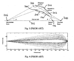
- Each mirror 200 is a thin shell consisting of two sections (surfaces) 202, 204: the first one 202, closer to the source 102 is a hyperboloid whereas the second 204 is an ellipsoid, both with rotational symmetry, with a focus in common.
- the light source 102 is placed in the focus of the hyperboloid different from the common focus.
- the light from the source 102 is collected by the hyperbolic section 202, reflected onto the elliptic section 204 and then concentrated to the focus of the ellipsoid, different from the common focus, and known as intermediate focus (IF) 206.
- IF intermediate focus
- the performance of the collector 102 is mainly characterized by the collection efficiency and the far field intensity distribution.
- the collection efficiency is the ratio between the light intensity at intermediate focus 206 and the power emitted by the source 102 into half a sphere.
- the collection efficiency is related to the geometry of the collector 104, to the reflectivity of each mirror 200, to the spatial and angular distribution of the source 102, to the optical specifications of the illuminator.
- the far field intensity distribution is the 2D spatial distribution of the light intensity beyond the intermediate focus 206 at distances that depends on the illuminator design but that are normally of the same order of magnitude as the distance between the source 102 and intermediate focus 206.
- the collector 104 is normally used in conjunction with a hot plasma source 102.
- the thermal load from UV radiation on the collector 104 is very high and a proper cooling system is required.
- the cooling system is positioned on the back surface of each mirror 200 in the shadow area that is present on the back side of both the elliptical section 204 and the hyperbolic section 202 (see Fig. 2 (PRIOR ART)).
- Fig. 3 in the design of a Wolter I mirror the hyperbolic 202 and the elliptical section 204 has a focus in common (304) that lays on the optical axis 302 (i.e. the line through the source focus 102 and the intermediate focus 206).
- This condition introduces a constraint in the design of the mirror 200, 200' with the consequence that the designer has one degree of freedom (one real parameter, corresponding to the position of the common focus 304 on the optical axis 302) for each mirror.
- the resulting total number of degrees of freedom is further reduced by the system specification for the whole collector 104, by manufacturing requirements, etc. It is then possible that, in order to satisfy all the requirements and boundary conditions, the design of the collector is not fully optimized in terms of optical performance.
- Fig. 4 PRIOR ART
- Table A.1 show the optical layout and prescriptions of a Wolter I collector 104 designed for the following specifications:
- Fig. 4 The design of Fig. 4 (PRIOR ART) collects the light from the source 102 up to an angle of 55.5°.
- the collection efficiency of the collector 104 shown in Fig. 4 (PRIOR ART) calculated for a point source and assuming a Ruthenium coating with theoretical reflectivity is 27.7% with respect to 2 ⁇ sr emission. Where comparative performance data are given herein for collector designs according to the present invention, these are relative to the design of Fig.. 4 .
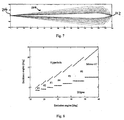
- Fig. 5 shows the grazing incidence angle on both the hyperbolic section 202 and elliptical section 204 as a function of the emission angle for the Wolter I collector 104 of Fig. 4 . It can be noted that the grazing incidence angle on the hyperbolic section 202 is always greater than the grazing incidence angle on the elliptical section 204. The consequence of this difference is a decrease of the efficiency of the collector 104 since the maximum optical transmission is achieved when the two angles are equal.
- the collector includes a first mirror shell for receiving a first ring aperture section of the light and irradiating a first planar ring section of the plane with a first irradiance, and a second mirror shell for receiving a second ring aperture section of the light and irradiating a second planar ring section of the plane with a second irradiance.
- the first and second mirror shells are rotationally symmetrical and concentrically arranged around a common axis of rotation, the first and second ring aperture sections do not overlap with one another, the first planar ring section substantially abuts the second planar ring section, and the first irradiance is approximately equal to the second irradiance. Nested collectors for EUV lithography are discussed.
- the plane is defined by a local coordinate system having a y-direction parallel to a scanning direction and an x-direction perpendicular to the scanning direction.
- the collector includes (a) a first mirror shell, (b) a second mirror shell within the first mirror shell, and (c) a fastening device for fastening the first and second mirror shells.
- the mirror shells are substantially rotational symmetric about a common rotational axis.
- the fastening device has a support spoke that extends in a radial direction of the mirror shells, and the support spoke, when projected into the plane, yields a projection that is non-parallel to the ⁇ -direction. Collectors for EUV microlithography applications are discussed.
- WO2004/095140A2 discloses a system and method for collecting radiation, more specifically dual hemispherical collectors, which may be used in an EUV lithography illumination system.
- the system comprises a first surface shaped to reflect radiation in a first hemisphere of a source to illuminate in a second hemisphere of the source; and a second surface shaped to reflect radiation in the second hemisphere of the source to an output plane.
- Wolter type collectors are shown.
- WO2006/050891A2 discloses a method of making a high-precision optical surface which may be used either as a Wolter-type segment in an X-ray mirror system or in a collector of a EUV lithography system or as a spherical, aspherical, or free form normal or grazing incidence mirror in an EUV lithography system.
- the optical surface is prepared by sagging a thin flat glass sheet onto a masterpiece, in particular a mandrel, made from a temperature-resistant material, such as an alumina based ceramic or a keatite glass ceramic.
- the glass sheet is polished to the desired surface roughness, is positioned to an upper surface of the masterpiece, and is heated to effect sagging onto the upper surface of the masterpiece for generating a shaped body. Thereafter, the shaped body is cooled and removed from the masterpiece, is mounted within a holder, is inspected for deviations from the specification preferably using interferometric measurements, and is corrected for defects, preferably using ion beam figuring.
- the collector includes a plurality of grazing incidence mirror shells, for use with a plasma source in EUV applications.
- the purpose of the collector 104 in EUV sources is to transfer the largest possible amount of in-band power emitted from the plasma to the next optical stage, the illuminator 106, of the lithographic tool 100 (see Fig. 1 ), the collector efficiency being as defined hereinabove. For a given maximum collection angle on the source side, the collector efficiency is mainly determined by collected angle and by the reflectivity of the coating on the optical surface of the mirrors.
- collector efficiency is significantly lower than it might be since the reflectivity of the coating is not exploited in the most efficient way; any improvement in the collector efficiency is highly desirable.
- a further problem is that, with the collector efficiencies available, there is imposed the need to develop extremely powerful sources, and to have high optical quality and stability in the collector.
- a further problem is that the number of degrees of freedom in the design of each mirror is limited.
- a further problem is that the collector lifetime may be relatively short due to exposure to extremely powerful sources.
- the present invention seeks to address the aforementioned and other issues.
- a collector optical system for EUV lithography in which radiation is collected from a radiation source and directed to an image focus, comprising: one or more mirrors, the or each mirror being symmetric about an optical axis extending through the radiation source and the or each mirror having at least first and second reflective surfaces, the first and second reflective surfaces having a common focus, whereby, in use, radiation from the source undergoes successive grazing incidence reflections at said first and second reflective surfaces; and wherein the common focus is transversely offset by a predetermined distance ⁇ r with respect the optical axis.
- the predetermined distance ⁇ r is such that an angle is made between the optical axis and a line through the image focus and the common focus.
- this angle may have any suitable value sufficient to obtain collector efficiency improvedment/optimisation.
- the angle may be in the range from about 0.01 mrad to 1000 mrad.
- the angle lies in the range from about 0.1 mrad to about 100 mrad. More preferably, the angle lies in the range from about 1 mrad to about 100 mrad. More preferably, the angle lies in the range from about 10 mrad to about 45 mrad.
- the or each mirror is formed as an electroformed monolithic component, and wherein the first and second reflective surfaces are each provided on a respective one of two contiguous sections of the mirror.
- the first reflective surface, closest to the source has a hyperbolic shape.
- the second reflective surface, furthest from the source is obtained by rotating an elliptical profile around an axis that is not an axis of symmetry of the ellipse.
- a plurality of mirrors is provided in nested configuration.
- two of more of the mirrors each have a different geometry.
- the mirrors are as specified in Tables B.1 and B.2 set out hereinbelow.
- the mirrors are as specified in Tables C.1 and C.2 set out hereinbelow.
- one or more of the mirrors has mounted thereon, for example on the rear side thereof, one or more devices for the thermal management of the mirror, for example cooling lines, Peltier cells and temperature sensors.
- one or more devices for the thermal management of the mirror for example cooling lines, Peltier cells and temperature sensors.
- one or more of the mirrors has mounted thereon, for example on the rear side thereof, one or more devices for the mitigation of debris from the source, for example erosion detectors, solenoids and RF sources.
- one or more devices for the mitigation of debris from the source for example erosion detectors, solenoids and RF sources.
- collector optical system for EUV lithography comprising the system of any of the preceding claims.
- an EUV lithography system comprising: a radiation source, for example a LPP source, the collector optical system according to the foregoing paragraph; an optical condenser; and a reflective mask.
- an imaging optical system for EUV or X-ray imaging comprising the system of any of claims 1 to 12 of the appended claims.
- an EUV or X-ray imaging system comprising: the imaging optical system according to the foregoing paragraph; and an imaging device, for example a CCD array, disposed at the image focus.
- An advantage of the invention is that the collection efficiency is improved and/or maximised.
- a further advantage of the invention lies in relaxing the effort in developing extremely powerful sources, improving the optical quality and stability of the collector output and increasing the collector lifetime.
- a further advantage of the invention is the to increase the number of degrees of freedom in the design of each mirror in order achieve higher optical performance.
- the design of each two-section mirror according to the present invention has two degrees of freedom instead of one: the position of the projection of the common focus on the optical axis and the offset of the common focus from the optical axis.
- references to an "image focus” are references to an image focus or an intermediate focus.
- collector 104 The design and construction of the collector 104 according to the invention is as set out above in relation to Figs 1 to 5 , except as described hereinafter.
- Figure 6 shows the partial optical layout of a nested collector according to the invention; the concept on which the present invention being outlined therein.
- the common focus 304 (of the hyperbolic 202 and elliptical 204 cross section shown in Fig. 6 ) is offset by a distance ⁇ r with respect to the optical axis 302.
- the full mirror 200, 200' is obtained by rotating the cross section of Fig. 6 through 360°.
- the common focus 304 describes a circle of radius ⁇ r around the optical axis 302.
- the surface of revolution obtained by the rotation of the cross section of Fig. 6 does not consist of a hyperbolic section and an elliptic section, even if this is so for the cross section that was used to start with.
- the or each mirror 200, 200' is manufactured using electroforming techniques, employing a suitably shaped mandrel, as is well known to persons skilled in the art.
- Figure 7 illustrates a ray diagram for a collector 104 according to a first embodiment of the invention.
- a nested collector 104 consists of 7 mirrors.
- the design is based on the same specifications as above.
- the corresponding design prescriptions are given in Table B.1 and Table B.2. Table B.1.
- Embodiment 1 Mirror # Hyperbola Ellipse Mirror radii [mm] Conic Constant Radius of curvature [mm] Conic Constant Radius of curvature [mm] Maximum Ellipse-hyperbola joint Minimum 1 -1.00872112 2.9617 -0.99645803 3.8706 48.5441 45.5219 31.8977 2 -1.01382850 5.1834 -0.99515149 5.4782 59.9054 56.5746 40.9869 3 -1.02086660 8.2484 -0.99291329 8.1715 73.6692 69.6104 50.5030 4 -1.03096769 13.0759 -0.98982510 12.0486 90.3490 85.5125 62.2750 5 -1.04633222 21.0751 -0.98613298 16.9594 110.2979 104.9712 77.6207 6 -1.06768617 32.7047 -0.98040519 24.6998 134.8325 128.5450 94.9206 7
- Embodiment 1 Mirror # Position of common focus w.r.t. intermediate focus Parallel to optical axis [mm] Transversal to optical axis [mm] 1 2181.5 30 2 2254 35.6 3 2297.5 45.4 4 2355.5 58 5 2428 69.2 6 2494.7 87.4 7 2515 111.2
- Fig. 7 collects the light from the source 102 up to an angle of 59.9°.
- the collection efficiency of the collector shown in Fig. 7 calculated for a point source and assuming a Ruthenium coating with theoretical reflectivity is 30.2% with respect to 2 ⁇ sr emission, i.e. 9% higher than the collection efficiency of the reference Wolter I collector of Fig. 4 .
- Figure 8 shows grazing incidence angle on both the hyperbolic and elliptical sections as a function of the emission angle, for the collector of Fig. 7 . It can be noted that the plots corresponding to the grazing incidence angles on the hyperbolic 202 and elliptic 204 section are still far apart from each other. Thus the main contribution to the increase of the collection efficiency with respect to the reference Wolter I design ( Fig. 4 ) is due to the increase of the collected angle from the source 102.
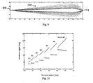
- Figure 9 illustrates a ray diagram for a collector 104 according to a second embodiment of the invention, consisting of 7 mirrors.
- the design is based on the same specifications as above.
- the corresponding design prescriptions are given in Table C.1 and Table C.2.
- the ends of the mirrors on the IF side are not aligned at the same position along the optical axis 302. This adds further degrees of freedom to the design allowing a further improvement of the optical performance.
- Embodiment 2 Mirror # Hyperbola Ellipse Mirror radii [mm] Conic Constant Radius of curvature [mm] Conic Constant Radius of curvature [mm] Maximum Ellipse-hyperbola joint Minimum 1 -1.01184308 3.1987 -0.99602012 4.0735 49.3046 46.1980 33.3707 2 -1.01757370 5.3379 -0.99473215 5.5785 59.8782 56.3148 41.2989 3 -1.02578746 8.2472 -0.99237091 8.2217 72.9209 68.5882 50.3699 4 -1.03814081 12.3532 -0.98860798 12.3675 88.8310 83.3322 60.6473 5 -1.06010381 18.1095 -0.98227521 18.9451 108.7425 101.3410 72.0890 6 -1.09432364 25.9728 -0.97108282 30.4147 134.4297 123.9259 84.4673
- Embodiment 2 Mirror # Position of common focus w.r.t intermediate focus Parallel to optical axis [mm] Transversal to optical axis [mm] 1 2042.85 23.75 2 2112.15 28.35 3 2146.8 36.4 4 2158.35 46.75 5 2117.925 55.95 6 2071.725 70.9 7 2008.2 90.45
- Fig. 9 collects the light from the source 102 up to an angle of 61.8°.
- the collection efficiency of the collector 104 shown in Fig. 9 calculated for a point source and assuming a Ruthenium coating with theoretical reflectivity is 32.2% with respect to 2 ⁇ sr emission, i.e. 16.2% higher than the collection efficiency of the reference Wolter I collector of Fig. 4 and 6 . 6% higher than the collection efficiency of the first embodiment of Figs s 7 and 8.
- Figure 10 shows grazing incidence angle on both the hyperbolic 202 and elliptical 204 sections as a function of the emission angle, for the collector of Fig. 9 . It can be noted that the plots corresponding to the grazing incidence angles on the hyperbolic 202 and elliptic 204 section are now closer than the first embodiment ( Fig. 8 ). Thus the increase of the collection efficiency is due to both the increase of the collected angle from the source 102 and the closer values of the reflection angles on the two surfaces 202, 204.
- collector optics for imaging e.g. EUV or X-ray
- imaging systems incorporating such optics the design of such imaging optics and imaging systems is discussed in, for example, European patent application no. 06425539.1 (publication member EP 1882984 A1 ).
Claims (16)
- Optisches Kollektorsystem (104) für EUV- und Röntgenstrahlenanwendungen, in dem Strahlung von einer Strahlungsquelle (102) gesammelt und auf einen Bildfokus (206) gerichtet wird, das Folgendes umfasst:einen oder mehrere Spiegel (200, 200'), wobei der oder jeder Spiegel um eine optische Achse (302) symmetrisch ist, die durch die Strahlungsquelle (102) verläuft, und wobei der oder jeder Spiegel (200, 200') wenigstens eine erste (202) und zweite (204) reflektierende Fläche aufweist, wobei die erste und zweite reflektierende Fläche einen gemeinsamen Fokus (304) haben, so dass beim Gebrauch Strahlung von der Quelle (104) aufeinander folgende streifende Einfallsreflektionen an der genannten ersten (202) und zweiten (204) reflektierenden Fläche erfährt;dadurch gekennzeichnet, dass der gemeinsame Fokus (304) um eine vorbestimmte Distanz Δr mit Bezug auf die optische Achse (302) transversal versetzt ist.
- System nach Anspruch 1, wobei die genannte vorbestimmte Distanz Δr derart ist, dass der Winkel zwischen der optischen Achse (302) und einer Linie durch den Bildfokus (206) und den gemeinsamen Fokus (304) im Bereich von etwa 1 mrad bis etwa 100 mrad liegt.
- System nach Anspruch 2, wobei der genannte Winkel im Bereich von etwa 10 mrad bis etwa 45 mrad liegt.
- System nach einem der vorherigen Ansprüche, wobei der oder jeder Spiegel (200, 200') als eine elektrogeformte monolithische Komponente ausgebildet ist und wobei die erste (202) und zweite (204) reflektierende Fläche jeweils auf einem von zwei nebeneinander liegenden Abschnitten des Spiegels (200, 200') vorgesehen sind.
- System nach einem der vorherigen Ansprüche, wobei für den oder jeden Spiegel (200, 200'):die erste reflektierende Fläche (202), die der Quelle am nächsten liegt, eine hyperbolische Form hat.
- System nach einem der vorherigen Ansprüche, wobei für den oder jeden Spiegel (200, 200'):die zweite reflektierende Fläche (204), die am weitesten von der Quelle entfernt ist, durch Drehen eines elliptischen Profils um eine Achse erhalten wird, die keine Symmetrieachse der Ellipse ist.
- System nach einem der vorherigen Ansprüche, wobei mehrere Spiegel (200, 200') in einer verschachtelten Konfiguration vorgesehen sind.
- System nach Anspruch 7, wobei zwei oder mehr der Spiegel (200, 200') jeweils eine andere Geometrie haben.
- System nach Anspruch 7 oder 8, wobei die Spiegel (200, 200') wie in den Tabellen B.1 und B.2 unten angegeben sind:
Tabelle B.1 Spiegel Nr. Hyperbel Ellipse Spiegelradien [mm] Konische Konstante Krümmungsradius [mm] Konische Konstante Krümmungs-radius[mm] Maximum Ellipse- Hyperbel-Verbindung Minimum 1 -1,00872112 2,9617 -0,99645803 3,8706 48,5441 45,5219 31,8977 2 -1,01382850 5,1834 -0,99515149 5,4782 59,9054 56,5746 40,9869 3 -1,02086660 8,2484 -0,99291329 8,1715 73,6692 69,6104 50,5030 4 -1,03096769 13,0759 -0,98982510 12,0486 90,3490 85,5125 62,2750 5 -1,04633222 21,0751 -0,98613298 16,9594 110,2979 104,9712 77,6207 6 -1,06768617 32,7047 -0,98040519 24,6998 134,8325 128,5450 94,9206 7 -1,10253986 49,8566 -0,97060467 37,5569 166,4799 158,1349 114,2194 Table B.2 Spiegel Nr. Position von gemeinsamem Fokus in Bez. auf Zwischenfokus Parallel zu optischer Achse [mm] Transversal zu optischer Achse [mm] 1 2181,5 30 2 2254 35,6 3 2297,5 45,4 4 2355,5 58 5 2428 69,2 6 2494,7 87,4 7 2515 111,2 - System nach Anspruch 7 oder 8, wobei die Spiegel (200, 200') wie in den Tabellen C1. und C.2 unten angegeben sind:
Tabelle C. 1 Spiegel Nr. Hyperbel Ellipse Spiegelradien [mm] Konische Konstante Krümmungsradius [mm] Konische Konstante Krümmungsradius [mm] Maximum Ellipse-Hyperbel-Verbindung Minimum 1 -1,01184308 3,1987 -0,99602012 4,0735 49,3046 46,1980 33,3707 2 -1,01757370 5,3379 -0,99473215 5,5785 59,8782 56,3148 41,2989 3 -1,02578746 8,2472 -0,99237091 8,2217 72,9209 68,5882 50,3699 4 -1,03814081 12,3532 -0,98860798 12,3675 88,8310 83,3322 60,6473 5 -1,06010381 18,1095 -0,98227521 18,9451 108,7425 101,3410 72,0890 6 -1,09432364 25,9728 -0,97108282 30,4147 134,4297 123,9259 84,4673 7 -1,15329957 36,8423 -0,95037239 51,1674 169,2152 153,3835 96,9687 Tabelle C.2 Spiegel Nr. Position von gemeinsamem Fokus in Bez. auf Zwischenfokus Parallel zu optischer Achse [mm] Transversal zu optischer Achse [mm] 1 2042,85 23,75 2 2112,15 28,35 3 2146,8 36,4 4 2158,35 46,75 5 2117,925 55,95 6 2071,725 70,9 7 2008,2 90,45 - System nach einem der vorherigen Ansprüche, wobei eine oder mehrere Vorrichtungen für das thermische Management des Spiegels (200, 200'), wie zum Beispiel Kühlleitungen, Peltier-Zellen und Temperatursensoren, an einem oder mehreren der Spiegel (200, 200'), z.B. auf der Rückseite davon, montiert ist/sind.
- System nach einem der vorherigen Ansprüche, wobei eine oder mehrere Vorrichtungen zum Verringern von Schmutz von der Quelle (102), zum Beispiel Erosionsdetektoren, Solenoide und RF-Quellen, in den ein oder mehreren Spiegeln (200, 200'), zum Beispiel auf der Rückseite davon, montiert ist/sind.
- Optisches Kollektorsystem für EUV-Lithografie, das das System (104) nach einem der vorherigen Ansprüche umfasst.
- EUV-Lithografiesystem (100), das Folgendes umfasst:eine Strahlungsquelle (102), zum Beispiel eine LPP-Quelle,das optische Kollektorsystem (104) nach Anspruch 13;einen optischen Kondensor (106); undeine reflektierende Maske (108).
- Optisches Abbildungssystem zur EUV- oder Röntgenstrahlenabbildung, das das System (104) nach einem der Ansprüche 1 bis 12 umfasst.
- EUV- oder Röntgenstrahlenabbildungssystem, das Folgendes umfasst:das optische Abbildungssystem nach Anspruch 15; undein Abbildungsgerät, zum Beispiel einen CCD-Array, das am Bildfokus (206) angeordnet ist.
Priority Applications (5)
| Application Number | Priority Date | Filing Date | Title |
|---|---|---|---|
| EP06425634A EP1901126B1 (de) | 2006-09-15 | 2006-09-15 | Optisches Kollektorsystem |
| AT06425634T ATE528693T1 (de) | 2006-09-15 | 2006-09-15 | Optisches kollektorsystem |
| US12/441,343 US8390785B2 (en) | 2006-09-15 | 2007-09-03 | Collector optical system |
| JP2009527724A JP5410283B2 (ja) | 2006-09-15 | 2007-09-03 | 集光光学系 |
| PCT/EP2007/007674 WO2008031514A2 (en) | 2006-09-15 | 2007-09-03 | A collector optical system |
Applications Claiming Priority (1)
| Application Number | Priority Date | Filing Date | Title |
|---|---|---|---|
| EP06425634A EP1901126B1 (de) | 2006-09-15 | 2006-09-15 | Optisches Kollektorsystem |
Publications (2)
| Publication Number | Publication Date |
|---|---|
| EP1901126A1 EP1901126A1 (de) | 2008-03-19 |
| EP1901126B1 true EP1901126B1 (de) | 2011-10-12 |
Family
ID=37686093
Family Applications (1)
| Application Number | Title | Priority Date | Filing Date |
|---|---|---|---|
| EP06425634A Active EP1901126B1 (de) | 2006-09-15 | 2006-09-15 | Optisches Kollektorsystem |
Country Status (5)
| Country | Link |
|---|---|
| US (1) | US8390785B2 (de) |
| EP (1) | EP1901126B1 (de) |
| JP (1) | JP5410283B2 (de) |
| AT (1) | ATE528693T1 (de) |
| WO (1) | WO2008031514A2 (de) |
Families Citing this family (21)
| Publication number | Priority date | Publication date | Assignee | Title |
|---|---|---|---|---|
| EP2083327B1 (de) * | 2008-01-28 | 2017-11-29 | Media Lario s.r.l. | Optische Systeme mit verbessertem Kollektor mit streifendem Einfall für EUV- und Röntgenstrahlungsanwendungen |
| EP2083328B1 (de) | 2008-01-28 | 2013-06-19 | Media Lario s.r.l. | Kollektor für streifenden Strahlungseinfall geeignet für lasererzeugte Plasmaquellen |
| US8050380B2 (en) * | 2009-05-05 | 2011-11-01 | Media Lario, S.R.L. | Zone-optimized mirrors and optical systems using same |
| RU2404444C1 (ru) * | 2009-12-29 | 2010-11-20 | Общество С Ограниченной Ответственностью "Инсмат Технология" | Способ фокусировки осесимметричного потока излучения, генерируемого источником волновой природы, и оптическая система для его осуществления |
| US8330131B2 (en) | 2010-01-11 | 2012-12-11 | Media Lario, S.R.L. | Source-collector module with GIC mirror and LPP EUV light source |
| JP5093267B2 (ja) * | 2010-03-11 | 2012-12-12 | ウシオ電機株式会社 | 集光鏡アッセンブリおよびこの集光鏡アッセンブリを用いた極端紫外光光源装置 |
| US8587768B2 (en) | 2010-04-05 | 2013-11-19 | Media Lario S.R.L. | EUV collector system with enhanced EUV radiation collection |
| DE102010028655A1 (de) * | 2010-05-06 | 2011-11-10 | Carl Zeiss Smt Gmbh | EUV-Kollektor |
| US8686381B2 (en) | 2010-06-28 | 2014-04-01 | Media Lario S.R.L. | Source-collector module with GIC mirror and tin vapor LPP target system |
| US20120050706A1 (en) | 2010-08-30 | 2012-03-01 | Media Lario S.R.L | Source-collector module with GIC mirror and xenon ice EUV LPP target system |
| US8344339B2 (en) | 2010-08-30 | 2013-01-01 | Media Lario S.R.L. | Source-collector module with GIC mirror and tin rod EUV LPP target system |
| US20120050707A1 (en) | 2010-08-30 | 2012-03-01 | Media Lario S.R.L | Source-collector module with GIC mirror and tin wire EUV LPP target system |
| US8258485B2 (en) | 2010-08-30 | 2012-09-04 | Media Lario Srl | Source-collector module with GIC mirror and xenon liquid EUV LPP target system |
| US8746975B2 (en) | 2011-02-17 | 2014-06-10 | Media Lario S.R.L. | Thermal management systems, assemblies and methods for grazing incidence collectors for EUV lithography |
| US8731139B2 (en) | 2011-05-04 | 2014-05-20 | Media Lario S.R.L. | Evaporative thermal management of grazing incidence collectors for EUV lithography |
| DE102013002064A1 (de) | 2012-02-11 | 2013-08-14 | Media Lario S.R.L. | Quell-kollektor-module für euv-lithographie unter verwendung eines gic-spiegels und einer lpp-quelle |
| DE102013204444A1 (de) * | 2013-03-14 | 2014-09-18 | Carl Zeiss Smt Gmbh | Beleuchtungsoptik für ein Maskeninspektionssystem sowie Maskeninspektionssystem mit einer derartigen Beleuchtungsoptik |
| JP6284073B2 (ja) * | 2013-07-12 | 2018-02-28 | 国立大学法人 東京大学 | 回転体ミラーを用いたx線集光システムの光学設計方法及びx線集光システム |
| JP2016180591A (ja) | 2013-07-24 | 2016-10-13 | 株式会社日立ハイテクノロジーズ | 検査装置 |
| CN104570623A (zh) * | 2015-02-16 | 2015-04-29 | 哈尔滨工业大学 | Xe介质毛细管放电检测用极紫外光源的光学收集系统 |
| WO2021162947A1 (en) * | 2020-02-10 | 2021-08-19 | Sigray, Inc. | X-ray mirror optics with multiple hyperboloidal / hyperbolic surface profiles |
Family Cites Families (8)
| Publication number | Priority date | Publication date | Assignee | Title |
|---|---|---|---|---|
| JPH0810561B2 (ja) * | 1988-11-30 | 1996-01-31 | 市光工業株式会社 | 前照灯の光学系 |
| DE10138313A1 (de) | 2001-01-23 | 2002-07-25 | Zeiss Carl | Kollektor für Beleuchtugnssysteme mit einer Wellenlänge < 193 nm |
| AU2002325359A1 (en) | 2001-08-10 | 2003-02-24 | Carl Zeiss Smt Ag | Collector with fastening devices for fastening mirror shells |
| SG109523A1 (en) * | 2002-08-15 | 2005-03-30 | Asml Netherlands Bv | Lithographic projection apparatus and reflector assembly for use in said apparatus |
| US7034320B2 (en) | 2003-03-20 | 2006-04-25 | Intel Corporation | Dual hemispherical collectors |
| ATE445900T1 (de) * | 2003-08-27 | 2009-10-15 | Zeiss Carl Smt Ag | Schiefspiegliges normal-incidence-kollektorsystem für lichtquellen, insbesondere euv- plasmaentladungsquellen |
| WO2006050891A2 (en) | 2004-11-09 | 2006-05-18 | Carl Zeiss Smt Ag | A high-precision optical surface prepared by sagging from a masterpiece |
| EP1980743B1 (de) * | 2007-04-10 | 2015-09-09 | Nissan Motor Co., Ltd. | Antriebsvorrichtung für eine Kraftstoffpumpe |
-
2006
- 2006-09-15 EP EP06425634A patent/EP1901126B1/de active Active
- 2006-09-15 AT AT06425634T patent/ATE528693T1/de not_active IP Right Cessation
-
2007
- 2007-09-03 WO PCT/EP2007/007674 patent/WO2008031514A2/en active Application Filing
- 2007-09-03 JP JP2009527724A patent/JP5410283B2/ja active Active
- 2007-09-03 US US12/441,343 patent/US8390785B2/en active Active
Also Published As
| Publication number | Publication date |
|---|---|
| EP1901126A1 (de) | 2008-03-19 |
| ATE528693T1 (de) | 2011-10-15 |
| US8390785B2 (en) | 2013-03-05 |
| US20100096557A1 (en) | 2010-04-22 |
| WO2008031514A2 (en) | 2008-03-20 |
| JP5410283B2 (ja) | 2014-02-05 |
| WO2008031514A3 (en) | 2008-05-02 |
| JP2010503882A (ja) | 2010-02-04 |
Similar Documents
| Publication | Publication Date | Title |
|---|---|---|
| EP1901126B1 (de) | Optisches Kollektorsystem | |
| EP2083327B1 (de) | Optische Systeme mit verbessertem Kollektor mit streifendem Einfall für EUV- und Röntgenstrahlungsanwendungen | |
| US7244954B2 (en) | Collector having unused region for illumination systems using a wavelength ≦193 nm | |
| KR101166658B1 (ko) | 입구퓨필의 네거티브 백포커스를 갖는 투사대물렌즈 및 투사노출장치 | |
| US6469827B1 (en) | Diffraction spectral filter for use in extreme-UV lithography condenser | |
| US7321126B2 (en) | Collector with fastening devices for fastening mirror shells | |
| EP1882984B1 (de) | Optische Multireflexionssysteme und ihre Herstellung | |
| US8253925B2 (en) | Catoptric illumination system for microlithography tool | |
| US9817220B2 (en) | Catadioptric projection objective comprising deflection mirrors and projection exposure method | |
| US20120050708A1 (en) | Source-collector module with GIC mirror and tin rod EUV LPP target system | |
| TW201017345A (en) | Collector assembly, radiation source, lithographic apparatus, and device manufacturing method | |
| WO2000048043A1 (en) | Extreme-uv lithography condenser | |
| JP5220136B2 (ja) | 照明光学系、露光装置およびデバイス製造方法 | |
| JP2000162415A (ja) | 反射鏡の製造方法又は反射型照明装置又は半導体露光装置 |
Legal Events
| Date | Code | Title | Description |
|---|---|---|---|
| PUAI | Public reference made under article 153(3) epc to a published international application that has entered the european phase |
Free format text: ORIGINAL CODE: 0009012 |
|
| AK | Designated contracting states |
Kind code of ref document: A1 Designated state(s): AT BE BG CH CY CZ DE DK EE ES FI FR GB GR HU IE IS IT LI LT LU LV MC NL PL PT RO SE SI SK TR |
|
| AX | Request for extension of the european patent |
Extension state: AL BA HR MK YU |
|
| 17P | Request for examination filed |
Effective date: 20080905 |
|
| 17Q | First examination report despatched |
Effective date: 20081015 |
|
| AKX | Designation fees paid |
Designated state(s): AT BE BG CH CY CZ DE DK EE ES FI FR GB GR HU IE IS IT LI LT LU LV MC NL PL PT RO SE SI SK TR |
|
| GRAP | Despatch of communication of intention to grant a patent |
Free format text: ORIGINAL CODE: EPIDOSNIGR1 |
|
| GRAC | Information related to communication of intention to grant a patent modified |
Free format text: ORIGINAL CODE: EPIDOSCIGR1 |
|
| GRAS | Grant fee paid |
Free format text: ORIGINAL CODE: EPIDOSNIGR3 |
|
| GRAA | (expected) grant |
Free format text: ORIGINAL CODE: 0009210 |
|
| AK | Designated contracting states |
Kind code of ref document: B1 Designated state(s): AT BE BG CH CY CZ DE DK EE ES FI FR GB GR HU IE IS IT LI LT LU LV MC NL PL PT RO SE SI SK TR |
|
| REG | Reference to a national code |
Ref country code: GB Ref legal event code: FG4D |
|
| REG | Reference to a national code |
Ref country code: CH Ref legal event code: EP |
|
| REG | Reference to a national code |
Ref country code: IE Ref legal event code: FG4D |
|
| REG | Reference to a national code |
Ref country code: DE Ref legal event code: R096 Ref document number: 602006025033 Country of ref document: DE Effective date: 20111208 |
|
| REG | Reference to a national code |
Ref country code: NL Ref legal event code: T3 |
|
| LTIE | Lt: invalidation of european patent or patent extension |
Effective date: 20111012 |
|
| REG | Reference to a national code |
Ref country code: AT Ref legal event code: MK05 Ref document number: 528693 Country of ref document: AT Kind code of ref document: T Effective date: 20111012 |
|
| PG25 | Lapsed in a contracting state [announced via postgrant information from national office to epo] |
Ref country code: BE Free format text: LAPSE BECAUSE OF FAILURE TO SUBMIT A TRANSLATION OF THE DESCRIPTION OR TO PAY THE FEE WITHIN THE PRESCRIBED TIME-LIMIT Effective date: 20111012 Ref country code: IS Free format text: LAPSE BECAUSE OF FAILURE TO SUBMIT A TRANSLATION OF THE DESCRIPTION OR TO PAY THE FEE WITHIN THE PRESCRIBED TIME-LIMIT Effective date: 20120212 Ref country code: LT Free format text: LAPSE BECAUSE OF FAILURE TO SUBMIT A TRANSLATION OF THE DESCRIPTION OR TO PAY THE FEE WITHIN THE PRESCRIBED TIME-LIMIT Effective date: 20111012 |
|
| PG25 | Lapsed in a contracting state [announced via postgrant information from national office to epo] |
Ref country code: PT Free format text: LAPSE BECAUSE OF FAILURE TO SUBMIT A TRANSLATION OF THE DESCRIPTION OR TO PAY THE FEE WITHIN THE PRESCRIBED TIME-LIMIT Effective date: 20120213 Ref country code: LV Free format text: LAPSE BECAUSE OF FAILURE TO SUBMIT A TRANSLATION OF THE DESCRIPTION OR TO PAY THE FEE WITHIN THE PRESCRIBED TIME-LIMIT Effective date: 20111012 Ref country code: GR Free format text: LAPSE BECAUSE OF FAILURE TO SUBMIT A TRANSLATION OF THE DESCRIPTION OR TO PAY THE FEE WITHIN THE PRESCRIBED TIME-LIMIT Effective date: 20120113 Ref country code: SE Free format text: LAPSE BECAUSE OF FAILURE TO SUBMIT A TRANSLATION OF THE DESCRIPTION OR TO PAY THE FEE WITHIN THE PRESCRIBED TIME-LIMIT Effective date: 20111012 Ref country code: SI Free format text: LAPSE BECAUSE OF FAILURE TO SUBMIT A TRANSLATION OF THE DESCRIPTION OR TO PAY THE FEE WITHIN THE PRESCRIBED TIME-LIMIT Effective date: 20111012 |
|
| PG25 | Lapsed in a contracting state [announced via postgrant information from national office to epo] |
Ref country code: CY Free format text: LAPSE BECAUSE OF FAILURE TO SUBMIT A TRANSLATION OF THE DESCRIPTION OR TO PAY THE FEE WITHIN THE PRESCRIBED TIME-LIMIT Effective date: 20111012 |
|
| PG25 | Lapsed in a contracting state [announced via postgrant information from national office to epo] |
Ref country code: SK Free format text: LAPSE BECAUSE OF FAILURE TO SUBMIT A TRANSLATION OF THE DESCRIPTION OR TO PAY THE FEE WITHIN THE PRESCRIBED TIME-LIMIT Effective date: 20111012 Ref country code: EE Free format text: LAPSE BECAUSE OF FAILURE TO SUBMIT A TRANSLATION OF THE DESCRIPTION OR TO PAY THE FEE WITHIN THE PRESCRIBED TIME-LIMIT Effective date: 20111012 Ref country code: DK Free format text: LAPSE BECAUSE OF FAILURE TO SUBMIT A TRANSLATION OF THE DESCRIPTION OR TO PAY THE FEE WITHIN THE PRESCRIBED TIME-LIMIT Effective date: 20111012 Ref country code: CZ Free format text: LAPSE BECAUSE OF FAILURE TO SUBMIT A TRANSLATION OF THE DESCRIPTION OR TO PAY THE FEE WITHIN THE PRESCRIBED TIME-LIMIT Effective date: 20111012 Ref country code: BG Free format text: LAPSE BECAUSE OF FAILURE TO SUBMIT A TRANSLATION OF THE DESCRIPTION OR TO PAY THE FEE WITHIN THE PRESCRIBED TIME-LIMIT Effective date: 20120112 |
|
| PLBE | No opposition filed within time limit |
Free format text: ORIGINAL CODE: 0009261 |
|
| STAA | Information on the status of an ep patent application or granted ep patent |
Free format text: STATUS: NO OPPOSITION FILED WITHIN TIME LIMIT |
|
| PG25 | Lapsed in a contracting state [announced via postgrant information from national office to epo] |
Ref country code: IT Free format text: LAPSE BECAUSE OF FAILURE TO SUBMIT A TRANSLATION OF THE DESCRIPTION OR TO PAY THE FEE WITHIN THE PRESCRIBED TIME-LIMIT Effective date: 20111012 Ref country code: RO Free format text: LAPSE BECAUSE OF FAILURE TO SUBMIT A TRANSLATION OF THE DESCRIPTION OR TO PAY THE FEE WITHIN THE PRESCRIBED TIME-LIMIT Effective date: 20111012 Ref country code: PL Free format text: LAPSE BECAUSE OF FAILURE TO SUBMIT A TRANSLATION OF THE DESCRIPTION OR TO PAY THE FEE WITHIN THE PRESCRIBED TIME-LIMIT Effective date: 20111012 |
|
| 26N | No opposition filed |
Effective date: 20120713 |
|
| REG | Reference to a national code |
Ref country code: DE Ref legal event code: R097 Ref document number: 602006025033 Country of ref document: DE Effective date: 20120713 |
|
| PG25 | Lapsed in a contracting state [announced via postgrant information from national office to epo] |
Ref country code: AT Free format text: LAPSE BECAUSE OF FAILURE TO SUBMIT A TRANSLATION OF THE DESCRIPTION OR TO PAY THE FEE WITHIN THE PRESCRIBED TIME-LIMIT Effective date: 20111012 |
|
| PG25 | Lapsed in a contracting state [announced via postgrant information from national office to epo] |
Ref country code: MC Free format text: LAPSE BECAUSE OF NON-PAYMENT OF DUE FEES Effective date: 20120930 Ref country code: ES Free format text: LAPSE BECAUSE OF FAILURE TO SUBMIT A TRANSLATION OF THE DESCRIPTION OR TO PAY THE FEE WITHIN THE PRESCRIBED TIME-LIMIT Effective date: 20120123 |
|
| REG | Reference to a national code |
Ref country code: CH Ref legal event code: PL |
|
| GBPC | Gb: european patent ceased through non-payment of renewal fee |
Effective date: 20120915 |
|
| REG | Reference to a national code |
Ref country code: IE Ref legal event code: MM4A |
|
| PG25 | Lapsed in a contracting state [announced via postgrant information from national office to epo] |
Ref country code: FI Free format text: LAPSE BECAUSE OF FAILURE TO SUBMIT A TRANSLATION OF THE DESCRIPTION OR TO PAY THE FEE WITHIN THE PRESCRIBED TIME-LIMIT Effective date: 20111012 |
|
| REG | Reference to a national code |
Ref country code: FR Ref legal event code: ST Effective date: 20130531 |
|
| PG25 | Lapsed in a contracting state [announced via postgrant information from national office to epo] |
Ref country code: IE Free format text: LAPSE BECAUSE OF NON-PAYMENT OF DUE FEES Effective date: 20120915 Ref country code: GB Free format text: LAPSE BECAUSE OF NON-PAYMENT OF DUE FEES Effective date: 20120915 Ref country code: CH Free format text: LAPSE BECAUSE OF NON-PAYMENT OF DUE FEES Effective date: 20120930 Ref country code: LI Free format text: LAPSE BECAUSE OF NON-PAYMENT OF DUE FEES Effective date: 20120930 |
|
| PG25 | Lapsed in a contracting state [announced via postgrant information from national office to epo] |
Ref country code: FR Free format text: LAPSE BECAUSE OF NON-PAYMENT OF DUE FEES Effective date: 20121001 |
|
| PG25 | Lapsed in a contracting state [announced via postgrant information from national office to epo] |
Ref country code: TR Free format text: LAPSE BECAUSE OF FAILURE TO SUBMIT A TRANSLATION OF THE DESCRIPTION OR TO PAY THE FEE WITHIN THE PRESCRIBED TIME-LIMIT Effective date: 20111012 |
|
| PG25 | Lapsed in a contracting state [announced via postgrant information from national office to epo] |
Ref country code: LU Free format text: LAPSE BECAUSE OF NON-PAYMENT OF DUE FEES Effective date: 20120915 |
|
| PG25 | Lapsed in a contracting state [announced via postgrant information from national office to epo] |
Ref country code: HU Free format text: LAPSE BECAUSE OF FAILURE TO SUBMIT A TRANSLATION OF THE DESCRIPTION OR TO PAY THE FEE WITHIN THE PRESCRIBED TIME-LIMIT Effective date: 20060915 |
|
| P01 | Opt-out of the competence of the unified patent court (upc) registered |
Effective date: 20230524 |
|
| PGFP | Annual fee paid to national office [announced via postgrant information from national office to epo] |
Ref country code: NL Payment date: 20231003 Year of fee payment: 18 |
|
| PGFP | Annual fee paid to national office [announced via postgrant information from national office to epo] |
Ref country code: DE Payment date: 20231003 Year of fee payment: 18 |