EP1901044B1 - Kapazitive Sensorenvorrichtung zur Erkennung der Anwesenheit von Fahrzeuginsassen - Google Patents
Kapazitive Sensorenvorrichtung zur Erkennung der Anwesenheit von Fahrzeuginsassen Download PDFInfo
- Publication number
- EP1901044B1 EP1901044B1 EP07075781.0A EP07075781A EP1901044B1 EP 1901044 B1 EP1901044 B1 EP 1901044B1 EP 07075781 A EP07075781 A EP 07075781A EP 1901044 B1 EP1901044 B1 EP 1901044B1
- Authority
- EP
- European Patent Office
- Prior art keywords
- force translation
- control circuit
- plate
- sensor apparatus
- conductor
- Prior art date
- Legal status (The legal status is an assumption and is not a legal conclusion. Google has not performed a legal analysis and makes no representation as to the accuracy of the status listed.)
- Not-in-force
Links
Images




Classifications
-
- G—PHYSICS
- G01—MEASURING; TESTING
- G01G—WEIGHING
- G01G19/00—Weighing apparatus or methods adapted for special purposes not provided for in the preceding groups
- G01G19/40—Weighing apparatus or methods adapted for special purposes not provided for in the preceding groups with provisions for indicating, recording, or computing price or other quantities dependent on the weight
- G01G19/413—Weighing apparatus or methods adapted for special purposes not provided for in the preceding groups with provisions for indicating, recording, or computing price or other quantities dependent on the weight using electromechanical or electronic computing means
- G01G19/414—Weighing apparatus or methods adapted for special purposes not provided for in the preceding groups with provisions for indicating, recording, or computing price or other quantities dependent on the weight using electromechanical or electronic computing means using electronic computing means only
- G01G19/4142—Weighing apparatus or methods adapted for special purposes not provided for in the preceding groups with provisions for indicating, recording, or computing price or other quantities dependent on the weight using electromechanical or electronic computing means using electronic computing means only for controlling activation of safety devices, e.g. airbag systems
-
- B—PERFORMING OPERATIONS; TRANSPORTING
- B60—VEHICLES IN GENERAL
- B60N—SEATS SPECIALLY ADAPTED FOR VEHICLES; VEHICLE PASSENGER ACCOMMODATION NOT OTHERWISE PROVIDED FOR
- B60N2/00—Seats specially adapted for vehicles; Arrangement or mounting of seats in vehicles
- B60N2/002—Seats provided with an occupancy detection means mounted therein or thereon
- B60N2/0021—Seats provided with an occupancy detection means mounted therein or thereon characterised by the type of sensor or measurement
-
- B—PERFORMING OPERATIONS; TRANSPORTING
- B60—VEHICLES IN GENERAL
- B60N—SEATS SPECIALLY ADAPTED FOR VEHICLES; VEHICLE PASSENGER ACCOMMODATION NOT OTHERWISE PROVIDED FOR
- B60N2/00—Seats specially adapted for vehicles; Arrangement or mounting of seats in vehicles
- B60N2/002—Seats provided with an occupancy detection means mounted therein or thereon
- B60N2/0021—Seats provided with an occupancy detection means mounted therein or thereon characterised by the type of sensor or measurement
- B60N2/0024—Seats provided with an occupancy detection means mounted therein or thereon characterised by the type of sensor or measurement for identifying, categorising or investigation of the occupant or object on the seat
-
- B—PERFORMING OPERATIONS; TRANSPORTING
- B60—VEHICLES IN GENERAL
- B60N—SEATS SPECIALLY ADAPTED FOR VEHICLES; VEHICLE PASSENGER ACCOMMODATION NOT OTHERWISE PROVIDED FOR
- B60N2/00—Seats specially adapted for vehicles; Arrangement or mounting of seats in vehicles
- B60N2/002—Seats provided with an occupancy detection means mounted therein or thereon
- B60N2/0021—Seats provided with an occupancy detection means mounted therein or thereon characterised by the type of sensor or measurement
- B60N2/003—Seats provided with an occupancy detection means mounted therein or thereon characterised by the type of sensor or measurement characterised by the sensor mounting location in or on the seat
- B60N2/0031—Seats provided with an occupancy detection means mounted therein or thereon characterised by the type of sensor or measurement characterised by the sensor mounting location in or on the seat mounted on the frame
-
- G—PHYSICS
- G01—MEASURING; TESTING
- G01G—WEIGHING
- G01G7/00—Weighing apparatus wherein the balancing is effected by magnetic, electromagnetic, or electrostatic action, or by means not provided for in the preceding groups
- G01G7/06—Weighing apparatus wherein the balancing is effected by magnetic, electromagnetic, or electrostatic action, or by means not provided for in the preceding groups by electrostatic action
-
- B—PERFORMING OPERATIONS; TRANSPORTING
- B60—VEHICLES IN GENERAL
- B60N—SEATS SPECIALLY ADAPTED FOR VEHICLES; VEHICLE PASSENGER ACCOMMODATION NOT OTHERWISE PROVIDED FOR
- B60N2210/00—Sensor types, e.g. for passenger detection systems or for controlling seats
- B60N2210/10—Field detection presence sensors
- B60N2210/12—Capacitive; Electric field
Definitions
- the present invention is directed to a capacitive sensor disposed in a vehicle seat for detecting the presence of a passenger on the seat.
- Occupant presence detection is frequently used in connection with air bags and other pyrotechnically deployed restraints as a means of determining if the restraints should be deployed in the event of sufficiently severe crash.
- One commonly employed way of detecting occupant presence involves installing a fluid-filled bladder in or under the bottom foam cushion of the vehicle seat and measuring the fluid pressure in the bladder with a pressure sensor. Exemplary systems of this type are disclosed, for example, in the U.S. Patent Nos. 5,987,370 and 6,246,936 to Murphy et al. , and the U.S. Patent Nos. 6,101,436 and 6,490,936 to Fortune et al. , all of which are assigned to Delphi Technologies, Inc..
- the cost of the pressure sensor can be avoided by providing conductor plates on or near the upper and lower surfaces of a fluid-filled bladder, and detecting changes in capacitance between the plates when the thickness of the bladder changes due to the presence of occupant weight. See, for example, the U.S. Patent No. 6,927,678 to Fultz et al. , assigned to Delphi Technologies, Inc.
- the upper and lower plates of a capacitive sensor are separated by a layer of foam or other compressible material instead of a fluid-filled bladder.
- a layer of foam or other compressible material instead of a fluid-filled bladder.
- the present invention is directed to an improved capacitive sensor apparatus disposed between the bottom cushion and frame of a seat.
- the sensor apparatus includes first and second mutually parallel rigid force translation plates biased apart by a set of springs, first and second conductor plates centrally affixed to inboard faces of the first and second force translation plates, and a control circuit responsive to the gap capacitance between the first and second conductor plates.
- the force translation plates are joined in a manner to maintain the conductor plates parallel to each other while permitting movement of either force translation plate relative to the other in a direction perpendicular to the force translation plates.
- the capacitive sensor apparatus of the present invention is disclosed herein in the context of an apparatus for sensing the weight applied to a vehicle seat by a passenger.
- the sensed weight is used for passenger presence detection, and for classifying a detected passenger as a child, an adult, or some other classification.
- a capacitive sensor comprises upper and lower conductor plates 28 and 30 separated by a dielectric substance (primarily air in the illustrated embodiment), and packaged such that weight applied to the seating surface of the seat reduces the separation distance of the conductor plates, thereby increasing the electrical capacitance between the upper and lower plates.
- the capacitive sensor apparatus is preferably disposed between the frame and bottom cushion of the seat as depicted herein, possibly with a felt pad disposed between the sensor apparatus and the seat frame, but it should be understood that the sensor apparatus may be installed in a different location such as in the bottom cushion, in or behind a back cushion, and so on. Also, it should be understood that the disclosed sensor apparatus may be used in other applications, both vehicular and non-vehicular.
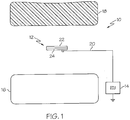
- the reference numeral 10 generally designates a seat bottom and a sensor apparatus according to this invention.
- the sensor apparatus 12 is disposed between the seat frame 16 and a foam seat cushion 18, and is coupled to an electronic control unit (ECU) 14 by an electrical cable 20.
- ECU electronice control unit
- the ECU 14 is an airbag control unit.
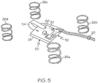
- the sensor apparatus 12 includes first and second rigid force translation plates 22, 24; a set of springs 26a, 26b, 26c, 26d; a first conductor plate 28 affixed to an inboard face of first force translation plate 22; a second conductor plate 30 affixed to an inboard face of second force translation plate 24; and a control circuit 32.
- the force translation plates are formed of molded plastic, and ribs formed on their inboard faces add rigidity to resist bending due to externally applied forces.
- the force translation plates 22 and 24 may be constructed of a non-insulative rigid material such as die-cast metal or stamped sheet metal, provided the conductor plates 28 and 30 are insulated from the respective force translation plates 22 and 24.
- the sensor apparatus 12 is mounted in seat 10 such that the first force translation plate 22 is facing upward (that is, toward the seat cushion 18), and the second force translation plate 24 is facing downward (that is, toward the seat frame 16).
- the conductor plate 28 is regarded as the upper conductor plate
- the conductor plate 30 is regarded as the lower conductor plate.
- the force translation plates 22 and 24 are joined in a manner to maintain the conductor plates 28 and 30 parallel to each other while permitting movement of either force translation plate 22, 24 relative to the other in a direction perpendicular to the force translation plates 22, 24.
- the conductor plates 28 and 30 are similar in size, and are affixed to the force translation plates 22 and 24 such that they substantially overlap each other.
- the conductor plates 28, 30 occupy a small portion of the force translation plates 22, 24; in the illustrated embodiment, the conductor plates 28, 30 have a surface area of approximately 1.69 in 2 , while the force translation plates have a surface area of approximately 16 in 2 .
- the inboard face of force translation plate 24 has a set of four inwardly extending snap posts 34a, 34b, 34c, 34d, and the force translation plate 22 has a set of corresponding openings 36a, 36b, 36c, 36d for receiving the snap posts 34a, 34b, 34c, 34d.
- the snap posts 34a, 34b, 34c, 34d of force translation plate 24 are each surrounded by a circular wall 38a, 38b, 38c, 38d.
- a boss 40a, 40b, 40c, 40d surrounding each opening 36a, 36b, 36c, 36d of force translation plate 22 nests in the space between a respective snap post 34a-34d and circular wall 38a-38d.
- the springs 26a-26d are disposed about the bosses 40a-40d between the force translation plates 22 and 24 to bias the plates 22 and 24 apart in a direction perpendicular to the plates 22, 24. As shown in FIG. 7 , interference between a given snap post 34a and an annular wall 42 of a respective boss 40a defines a maximum separation distance of the force translation plates 22 and 24.
- the parameters of springs 26a-26d are selected to achieve a desired force vs. deflection characteristic by setting both the spring pre-load (i.e., the spring bias force at the maximum separation distance of force translation plates 22 and 24) and the spring rate (i.e., the force vs. deflection relationship for passenger force in excess of the pre-load bias force.
- the conductor plate 28 occupies one face of a single-sided printed circuit board 50 that is affixed to the inboard face of force translation plate 22 by an adhesive, for example.
- the conductor plate 30 occupies one face of a double-sided circuit board 52, and the control circuit 32 is disposed on the opposite face of circuit board 52.
- the force translation plate 24 is provided with a central opening 24a and an inwardly extending shoulder or ledge 24b within the opening 24a.
- the margin of circuit board 52 is supported on the ledge 24b, with the conductor plate 30 facing the conductor plate 28. This leaves the control circuit 32 exposed.
- FIG. 8-9 the force translation plate 24 is provided with a central opening 24a and an inwardly extending shoulder or ledge 24b within the opening 24a.
- the margin of circuit board 52 is supported on the ledge 24b, with the conductor plate 30 facing the conductor plate 28. This leaves the control circuit 32 exposed.
- FIG. 8-9 the force translation plate 24 is provided with a central opening 24a and an inward
- the single-sided printed circuit board 50 is provided with a flexible circuit pig-tail or runner 54 carrying a conductor trace 54a that is electrically tied to the conductor plate 28.
- the flexible runner 54 is disposed in part in a channel 56 formed on the inboard face of plate 22, and extends through a slot aperture 58 formed in the force translation plate 24 adjacent the opening 24a.
- the conductor trace 54a terminates in a solderable tab 60, which is soldered to a terminal of control circuit 32 to electrically couple the conductor plate 28 to the control circuit 32.
- the runner 54 is implemented as a flexible strip circuit in the illustrated embodiment, it should be understood that it could alternately be implemented with a different kind of flexible conductor such as a simple wire or a conductive spring.
- the sensor apparatus 12 is assembled as follows. First, the circuit board 50 is affixed to the inboard face of force translation plate 22, and the flexible runner 54 is threaded through the slot aperture 58 of force translation plate 24. The springs 26a-26d are positioned about the bosses 40a-40d of force translation plate 22, and the force translation plates 22 and 24 are snapped together, with the snap posts 34a-34d of plate 24 passing into the openings 36a-36d of plate 22.
- the circuit board 52 is then placed on (or affixed to) the ledge 24b of force translation plate 24 with the control circuit 32 facing outward, and the tab 60 at the end of flexible runner 54 is soldered to a terminal of control circuit 32. Potting material (not shown) is then dispensed onto the exposed face of control circuit 32 within the sidewalls of opening 24a. When cured, the potting material seals the control circuit 32 and retains the circuit board 52 in place on ledge 24b.
- the cable 20 between ECU 14 and control circuit 32 can be directly connected to control circuit terminals, with the potting material in opening 24a of force translation plate 24 fixing the cable 20 with respect to the control circuit 32.
- the cable 20 will usually have a connector at each end to facilitate installation in a seat 10.
- the sensor apparatus 12 will usually be provided with a connector as well. This may be accomplished most easily by mounting a connector (including electrical terminals supported in a plastic housing) such as designated by the reference numeral 62 in FIGS. 8-9 directly on the exposed face of circuit board 52 such that it is surrounded by the potting material dispensed into opening 24a of force translation plate 24.
- the connector housing will protrude from the potting material so that it is accessible for attachment to the cable connector. If the potting material is sufficiently thick, it will serve when cured to fix the connector with respect to the rest of the sensor apparatus 12, and isolate the circuit board 52 from forces applied to the connector housing.
- Another approach, depicted in FIGS. 8-9 is to integrate the connector 62 into the outboard face of force translation plate 24, and to internally couple the connector terminals 62a to the control circuit 32. Referring to FIG. 9 , this may be achieved with a set of compliant pins 64 and a set of insert molded conductors 66.
- the compliant pins 64 extend out of an extension 68 of ledge 24b such that they pass through plated through-holes formed in the margin of circuit board 52 when circuit board 52 is installed on the ledge 24a.
- the plated through-holes are electrically coupled to control circuit terminals, and the insert-molded conductors 66 electrically tie the compliant pins 64 to the connector terminals 62a.
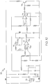
- FIG. 10 is a schematic diagram of the control circuit 32.
- the control circuit 32 is designed to measure the gap capacitance between the conductor plates 28 and 30. This capacitance will vary depending on the separation distance of plates 28 and 30. When the seat 10 is unoccupied, the separation distance is approximately 0.210 inch, and the gap capacitance has a relatively low value such as 5pF. When the seated weight of a passenger is sufficient to fully compress the sensor apparatus 12, the separation distance will be approximately 0.050 inch, and the gap capacitance will have a relatively high value such as 25pF.
- the gap capacitance is represented by the capacitor 70.
- the capacitance of capacitor 70 is evaluated by a constant current source formed by operational amplifier 72, configured as a voltage-to-current converter.
- a high control voltage applied to the non-inverting input 72a of amplifier 72 will exceed the voltage applied to the inverting input 72b of amplifier 72; in this case the output 72c of amplifier 72 is driven to a high state, and a charging current flows through capacitor 70 as indicated by arrow C.
- a low control voltage at the non-inverting input 72a drives the output 72c of amplifier 72 to a low state, and a discharging current flows through capacitor 70 as indicated by arrow D.
- the output 72c of amplifier 72 is applied to the non-inverting input 74a of comparator 74 so that its output 74b transitions from high to low with the charging and discharging of capacitor 70.
- the comparator 74 also has hysteresis to allow output voltage operation of amplifier 72 from 2 to 4 volts.
- the square-wave output voltage of comparator 74 regulates the control voltage applied to the non-inverting input 72a of amplifier 72.
- the output 74b of comparator 74 is also capacitively coupled to the base of transistor 76 to provide a corresponding output at pin 2 of the harness connector 78, which also serves as a power supply for the circuit via zener diode 80. In other words, the transistor 76 modulates the power supply bus at the charge/discharge frequency of capacitor 70.
- the output 72c of amplifier 72 is a triangular waveform due to the charging and discharging of capacitor 70. Since the charge and discharge rates vary with the capacitance of capacitor 70, the frequency of the waveform provides a measure of the capacitance - that is, the gap capacitance between conductor plates 28 and 30.
- the power supply bus is modulated at the same frequency, and ECU 14 determines the frequency by measuring the supply bus modulation over a full cycle. This has the benefit of compensating for slowly changing external static fields since the effect of such a field is balanced out over a full cycle of the triangular waveform.
- the present invention provides a practical and cost-effective sensor apparatus for passenger presence detection. While the apparatus has been described in reference to the illustrated embodiment, it should be understood that various modifications in addition to those mentioned above will occur to persons skilled in the art.
- the conductor plates 28 and 30 may be patterned instead of solid, and so forth.
- the space between conductor plates 28 and 30 can be at least partially filled with a crushable or displaceable medium such as silicone gel in order to minimize changes in the sensor capacitance due to humidity variations in the vicinity of the sensor apparatus 12; alternately, the control circuit 32 could include a humidity sensor in order to electrically compensate for any variability due to humidity.
- capacitance is simply a way of characterizing the change in electric field coupling between the first and second conductor plates 28 and 30, and any technique for measuring the change in such coupling is essentially equivalent for purposes of this invention. Accordingly, it is intended that the invention not be limited to the disclosed embodiment, but that it have the full scope permitted by the language of the following claims.
Landscapes
- Engineering & Computer Science (AREA)
- Physics & Mathematics (AREA)
- Aviation & Aerospace Engineering (AREA)
- Transportation (AREA)
- Mechanical Engineering (AREA)
- Mathematical Physics (AREA)
- Theoretical Computer Science (AREA)
- General Physics & Mathematics (AREA)
- Electromagnetism (AREA)
- Seats For Vehicles (AREA)
- Geophysics And Detection Of Objects (AREA)
Claims (7)
- Sensorvorrichtung (12) zum Erfassen der Anwesenheit eines Insassen auf einem Sitz (10), die aufweist:erste und zweite starre planare Kraftumwandlungsplatten (22, 24), die in dem Sitz (10) angeordnet sind;erste und zweite Leiterplatten (28, 30), die durch eine dielektrische Substanz getrennt sind und zentral an Innenseiten der ersten bzw. zweiten Kraftumwandlungsplatten (22, 24) befestigt sind; undeine Steuerschaltung (32), die auf eine Spaltkapazität zwischen der ersten und der zweiten Leiterplatte (28, 30) anspricht, zum Erfassen der Anwesenheit des Insassen, wenn ein Gewicht des Insassen die Vorspannkraft der Federn (26) übersteigt;dadurch gekennzeichnet, dass sie weiter aufweist:wobeiVerbindungsmittel (34, 40) zum Verbinden der Kraftumwandlungsplatten (22, 24) auf eine Weise, die sie im Wesentlichen parallel zueinander hält, während eine Bewegung einer der Kraftumwandlungsplatten relativ zu den anderen in einer Richtung senkrecht zu den Kraftumwandlungsplatten (22, 24) möglich ist;einen Satz von Federn (26), die zwischen den ersten und zweiten Kraftumwandlungsplatten (22, 24) angeordnet sind, um eine Vorspannkraft auszuüben, die die ersten und zweiten Kraftumwandlungsplatten (22, 24) in der senkrechten Richtung auseinander bringt;die erste Leiterplatte (28) auf einer ersten Schaltungsplatte (50) ausgebildet ist, die an der Innenseite der ersten Kraftumwandlungsplatte (22) befestigt ist; unddie zweite Leiterplatte (30) und die Steuerschaltung (32) an gegenüberliegenden Seiten einer zweiten Schaltungsplatte (52) angebracht sind, die an der Innenseite der zweiten Kraftumwandlungsplatte (24) befestigt ist.
- Die Sensorvorrichtung gemäß Anspruch 1, wobei die Steuerschaltung (32) elektrisch mit der zweiten Leiterplatte (30) durch die zweite Schaltungsplatte (52) gekoppelt ist und die Vorrichtung (12) zusätzlich ein leitendes Element (54) aufweist, das die erste Leiterplatte (28) mit der Steuerschaltung (32) elektrisch koppelt.
- Die Sensorvorrichtung gemäß Anspruch 2, wobei weiter:die Steuerschaltung (32) an einer Außenfläche der zweiten Schaltungsplatte (52) angebracht ist;das leitende Element ein flexibler Leiter (54) ist; undder flexible Leiter (54) durch eine Schlitzöffnung (58) in der zweiten Kraftumwandlungsplatte (24) angrenzend an die zweite Schaltungsplatte (52) verläuft, um die Steuerschaltung (32) zu erreichen.
- Die Sensorvorrichtung gemäß Anspruch 1, wobei:die zweite Kraftumwandlungsplatte (24) eine zentrale Öffnung (24a) mit einem inneren Absatz (24b) hat, der in der Öffnung (24a) versenkt ist; unddie Steuerschaltung (32) an einer Außenfläche einer Schaltungsplatte (52) angebracht ist, die innerhalb der zentralen Öffnung (24a) angeordnet ist und an dem inneren Absatz (24b) gestützt wird.
- Die Sensorvorrichtung gemäß Anspruch 4, wobei:die zweite Kraftumwandlungsplatte (24) eine Schlitzöffnung (58) angrenzend an die zentrale Öffnung (24a) hat; unddie erste Leiterplatte (28) elektrisch mit der Steuerschaltung (32) durch einen flexiblen Leiter (54) gekoppelt ist, der durch die Schlitzöffnung (58) verläuft.
- Die Sensorvorrichtung gemäß Anspruch 4, wobei:die zweite Kraftumwandlungsplatte (24) einen elektrischen Verbinder (62) zum Koppeln der Steuerschaltung (32) mit einem entfernten elektronischen Modul (14) und eingegossene Leiter (62a, 64, 66) umfasst, die zwischen der Steuerschaltung (32) und dem elektrischen Verbinder (62) gekoppelt sind.
- Die Sensorvorrichtung gemäß Anspruch 6, wobei die eingegossenen Leiter einen Satz konformer Stifte (64) umfassen, die von dem inneren Absatz (24b) vorstehen und durch einen Rand der Schaltungsplatte (52) verlaufen.
Applications Claiming Priority (2)
| Application Number | Priority Date | Filing Date | Title |
|---|---|---|---|
| US84462106P | 2006-09-14 | 2006-09-14 | |
| US11/706,016 US7434481B2 (en) | 2006-09-14 | 2007-02-14 | Capacitive sensor apparatus for passenger presence detection |
Publications (3)
| Publication Number | Publication Date |
|---|---|
| EP1901044A2 EP1901044A2 (de) | 2008-03-19 |
| EP1901044A3 EP1901044A3 (de) | 2011-04-20 |
| EP1901044B1 true EP1901044B1 (de) | 2019-01-16 |
Family
ID=38739972
Family Applications (1)
| Application Number | Title | Priority Date | Filing Date |
|---|---|---|---|
| EP07075781.0A Not-in-force EP1901044B1 (de) | 2006-09-14 | 2007-09-10 | Kapazitive Sensorenvorrichtung zur Erkennung der Anwesenheit von Fahrzeuginsassen |
Country Status (2)
| Country | Link |
|---|---|
| US (1) | US7434481B2 (de) |
| EP (1) | EP1901044B1 (de) |
Families Citing this family (8)
| Publication number | Priority date | Publication date | Assignee | Title |
|---|---|---|---|---|
| US7644628B2 (en) * | 2005-12-16 | 2010-01-12 | Loadstar Sensors, Inc. | Resistive force sensing device and method with an advanced communication interface |
| US20110133755A1 (en) | 2009-12-08 | 2011-06-09 | Delphi Technologies, Inc. | System and Method of Occupant Detection with a Resonant Frequency |
| US8178797B2 (en) * | 2009-12-30 | 2012-05-15 | Mettler-Toledo, LLC | Hermetically sealed scale platform |
| US8371877B2 (en) * | 2010-05-05 | 2013-02-12 | Sabritec, Inc. | Electrical connector with printed circuit board subassembly |
| US20130192904A1 (en) * | 2012-01-26 | 2013-08-01 | Delphi Technologies, Inc. | Occupant detection sensor assembly with integrated fasteners |
| DE102013004031A1 (de) * | 2013-03-08 | 2014-09-11 | Würth Elektronik Ics Gmbh & Co. Kg | Sensorvorrichtung und Ablagevorrichtung mit einer Sensorvorrichtung |
| US10017078B2 (en) * | 2013-05-30 | 2018-07-10 | Yefim G Kriger | Relocatable/replaceable pad for accurate vehicle occupant weight measurement |
| US20190100122A1 (en) * | 2017-10-04 | 2019-04-04 | Ford Global Technologies, Llc | Waterproof skinned bench seat |
Family Cites Families (10)
| Publication number | Priority date | Publication date | Assignee | Title |
|---|---|---|---|---|
| US5353641A (en) * | 1992-08-07 | 1994-10-11 | Ford Motor Company | Digital capacitive accelerometer |
| US5641202A (en) * | 1996-01-16 | 1997-06-24 | Lear Seating Corporation | Release latch for utility seat |
| US5900592A (en) * | 1997-08-29 | 1999-05-04 | Lockheed Martin Energy Research Corp. | Load sensing system |
| US5987370A (en) * | 1997-09-03 | 1999-11-16 | Delco Electronics Corp. | Vehicle occupant weight estimation apparatus having fluid-filled seat bladder |
| US5975958A (en) * | 1997-10-14 | 1999-11-02 | The Whitaker Corporation | Capactive coupling adapter for an electrical connector |
| US6246936B1 (en) * | 1999-10-05 | 2001-06-12 | Delphi Technologies, Inc. | Vehicle occupant characterization method based on sensed occupant weight |
| US6927678B2 (en) | 2003-08-18 | 2005-08-09 | Delphi Technologies, Inc. | Fluid filled seat bladder with capacitive sensors for occupant classification and weight estimation |
| US6999301B1 (en) | 2005-02-08 | 2006-02-14 | Delphi Technologies, Inc. | Capacitive load cell apparatus having an annealed synthetic woven spring dielectric |
| US7176390B2 (en) | 2005-03-02 | 2007-02-13 | Delphi Technologies, Inc. | Capacitive load cell with multi-layer dielectric for extended range |
| US7159471B2 (en) * | 2005-03-02 | 2007-01-09 | Delphi Technologies, Inc. | Capacitive load cell apparatus having silicone-impregnated foam dielectric pads |
-
2007
- 2007-02-14 US US11/706,016 patent/US7434481B2/en active Active
- 2007-09-10 EP EP07075781.0A patent/EP1901044B1/de not_active Not-in-force
Non-Patent Citations (1)
| Title |
|---|
| None * |
Also Published As
| Publication number | Publication date |
|---|---|
| US20080066563A1 (en) | 2008-03-20 |
| EP1901044A3 (de) | 2011-04-20 |
| US7434481B2 (en) | 2008-10-14 |
| EP1901044A2 (de) | 2008-03-19 |
Similar Documents
| Publication | Publication Date | Title |
|---|---|---|
| EP1901044A2 (de) | Kapazitive Sensorenvorrichtung zur Erkennung der Anwesenheit von Fahrzeuginsassen | |
| US7679378B2 (en) | Dual function capacitive sensor for seat occupant detection | |
| US6559555B1 (en) | Passenger detection system and detection method | |
| US7159897B2 (en) | Isolated ground for horn mechanism | |
| US7598881B2 (en) | Sensor and circuit configuration for occupant detection | |
| JP5748362B2 (ja) | 乗員検出および分類システム | |
| CN109501708B (zh) | 用于气囊的压力传感装置 | |
| CN100473568C (zh) | 用于安装在机动车辆方向盘中的驾驶员气囊模块的发生器支撑件 | |
| JP3650028B2 (ja) | 特にホーンを鳴らすためのスイッチング素子を有するステアリングホイール | |
| EP1961625A2 (de) | Schalterbasierter Sitzsensor für die Insassenanwesenheitserkennung | |
| CN101970263A (zh) | 安全装置以及用于生产安全装置的方法 | |
| US20110187346A1 (en) | Current detecting device | |
| EP2620317A1 (de) | Insassenerkennungssensoranordnung mit integrierten Befestigungsvorrichtungen | |
| US5684336A (en) | Crash sensor assembly including both an inertia sensor and an accelerometer and method | |
| US20130003272A1 (en) | Touch sensor mechanical interface | |
| WO2017129433A1 (en) | Capacitive occupant classification sensor with load-dependent antenna area | |
| US6481745B2 (en) | Driver Air bag module horn with improved assembly and functionality characteristics | |
| US20090014228A1 (en) | Collision detector | |
| US5679897A (en) | Piezoelectric type acceleration sensor with metallic case and resin package | |
| CN110361034A (zh) | 电容式传感器单元 | |
| CN115871767A (zh) | 方向盘和利用方向盘启动车辆内预设功能的方法 | |
| US7443075B2 (en) | Entrapment detecting system | |
| EP1503194A2 (de) | Kraftwandler | |
| KR100335857B1 (ko) | 승객 검출 시스템 및 검출 방법 | |
| KR102074763B1 (ko) | 차량용 배터리 센서 |
Legal Events
| Date | Code | Title | Description |
|---|---|---|---|
| PUAI | Public reference made under article 153(3) epc to a published international application that has entered the european phase |
Free format text: ORIGINAL CODE: 0009012 |
|
| AK | Designated contracting states |
Kind code of ref document: A2 Designated state(s): AT BE BG CH CY CZ DE DK EE ES FI FR GB GR HU IE IS IT LI LT LU LV MC MT NL PL PT RO SE SI SK TR |
|
| AX | Request for extension of the european patent |
Extension state: AL BA HR MK YU |
|
| PUAL | Search report despatched |
Free format text: ORIGINAL CODE: 0009013 |
|
| AK | Designated contracting states |
Kind code of ref document: A3 Designated state(s): AT BE BG CH CY CZ DE DK EE ES FI FR GB GR HU IE IS IT LI LT LU LV MC MT NL PL PT RO SE SI SK TR |
|
| AX | Request for extension of the european patent |
Extension state: AL BA HR MK RS |
|
| 17P | Request for examination filed |
Effective date: 20111020 |
|
| AKX | Designation fees paid |
Designated state(s): AT BE BG CH CY CZ DE DK EE ES FI FR GB GR HU IE IS IT LI LT LU LV MC MT NL PL PT RO SE SI SK TR |
|
| 17Q | First examination report despatched |
Effective date: 20160909 |
|
| STAA | Information on the status of an ep patent application or granted ep patent |
Free format text: STATUS: EXAMINATION IS IN PROGRESS |
|
| GRAP | Despatch of communication of intention to grant a patent |
Free format text: ORIGINAL CODE: EPIDOSNIGR1 |
|
| STAA | Information on the status of an ep patent application or granted ep patent |
Free format text: STATUS: GRANT OF PATENT IS INTENDED |
|
| INTG | Intention to grant announced |
Effective date: 20180801 |
|
| GRAS | Grant fee paid |
Free format text: ORIGINAL CODE: EPIDOSNIGR3 |
|
| GRAA | (expected) grant |
Free format text: ORIGINAL CODE: 0009210 |
|
| STAA | Information on the status of an ep patent application or granted ep patent |
Free format text: STATUS: THE PATENT HAS BEEN GRANTED |
|
| RAP1 | Party data changed (applicant data changed or rights of an application transferred) |
Owner name: APTIV TECHNOLOGIES LIMITED |
|
| AK | Designated contracting states |
Kind code of ref document: B1 Designated state(s): AT BE BG CH CY CZ DE DK EE ES FI FR GB GR HU IE IS IT LI LT LU LV MC MT NL PL PT RO SE SI SK TR |
|
| REG | Reference to a national code |
Ref country code: GB Ref legal event code: FG4D |
|
| REG | Reference to a national code |
Ref country code: CH Ref legal event code: EP |
|
| REG | Reference to a national code |
Ref country code: IE Ref legal event code: FG4D |
|
| REG | Reference to a national code |
Ref country code: DE Ref legal event code: R096 Ref document number: 602007057424 Country of ref document: DE |
|
| REG | Reference to a national code |
Ref country code: AT Ref legal event code: REF Ref document number: 1090037 Country of ref document: AT Kind code of ref document: T Effective date: 20190215 |
|
| REG | Reference to a national code |
Ref country code: NL Ref legal event code: MP Effective date: 20190116 |
|
| REG | Reference to a national code |
Ref country code: LT Ref legal event code: MG4D |
|
| PG25 | Lapsed in a contracting state [announced via postgrant information from national office to epo] |
Ref country code: NL Free format text: LAPSE BECAUSE OF FAILURE TO SUBMIT A TRANSLATION OF THE DESCRIPTION OR TO PAY THE FEE WITHIN THE PRESCRIBED TIME-LIMIT Effective date: 20190116 |
|
| REG | Reference to a national code |
Ref country code: AT Ref legal event code: MK05 Ref document number: 1090037 Country of ref document: AT Kind code of ref document: T Effective date: 20190116 |
|
| PG25 | Lapsed in a contracting state [announced via postgrant information from national office to epo] |
Ref country code: ES Free format text: LAPSE BECAUSE OF FAILURE TO SUBMIT A TRANSLATION OF THE DESCRIPTION OR TO PAY THE FEE WITHIN THE PRESCRIBED TIME-LIMIT Effective date: 20190116 Ref country code: LT Free format text: LAPSE BECAUSE OF FAILURE TO SUBMIT A TRANSLATION OF THE DESCRIPTION OR TO PAY THE FEE WITHIN THE PRESCRIBED TIME-LIMIT Effective date: 20190116 Ref country code: PL Free format text: LAPSE BECAUSE OF FAILURE TO SUBMIT A TRANSLATION OF THE DESCRIPTION OR TO PAY THE FEE WITHIN THE PRESCRIBED TIME-LIMIT Effective date: 20190116 Ref country code: SE Free format text: LAPSE BECAUSE OF FAILURE TO SUBMIT A TRANSLATION OF THE DESCRIPTION OR TO PAY THE FEE WITHIN THE PRESCRIBED TIME-LIMIT Effective date: 20190116 Ref country code: FI Free format text: LAPSE BECAUSE OF FAILURE TO SUBMIT A TRANSLATION OF THE DESCRIPTION OR TO PAY THE FEE WITHIN THE PRESCRIBED TIME-LIMIT Effective date: 20190116 Ref country code: PT Free format text: LAPSE BECAUSE OF FAILURE TO SUBMIT A TRANSLATION OF THE DESCRIPTION OR TO PAY THE FEE WITHIN THE PRESCRIBED TIME-LIMIT Effective date: 20190516 |
|
| PG25 | Lapsed in a contracting state [announced via postgrant information from national office to epo] |
Ref country code: BG Free format text: LAPSE BECAUSE OF FAILURE TO SUBMIT A TRANSLATION OF THE DESCRIPTION OR TO PAY THE FEE WITHIN THE PRESCRIBED TIME-LIMIT Effective date: 20190416 Ref country code: GR Free format text: LAPSE BECAUSE OF FAILURE TO SUBMIT A TRANSLATION OF THE DESCRIPTION OR TO PAY THE FEE WITHIN THE PRESCRIBED TIME-LIMIT Effective date: 20190417 Ref country code: LV Free format text: LAPSE BECAUSE OF FAILURE TO SUBMIT A TRANSLATION OF THE DESCRIPTION OR TO PAY THE FEE WITHIN THE PRESCRIBED TIME-LIMIT Effective date: 20190116 Ref country code: IS Free format text: LAPSE BECAUSE OF FAILURE TO SUBMIT A TRANSLATION OF THE DESCRIPTION OR TO PAY THE FEE WITHIN THE PRESCRIBED TIME-LIMIT Effective date: 20190516 |
|
| REG | Reference to a national code |
Ref country code: DE Ref legal event code: R097 Ref document number: 602007057424 Country of ref document: DE |
|
| PG25 | Lapsed in a contracting state [announced via postgrant information from national office to epo] |
Ref country code: SK Free format text: LAPSE BECAUSE OF FAILURE TO SUBMIT A TRANSLATION OF THE DESCRIPTION OR TO PAY THE FEE WITHIN THE PRESCRIBED TIME-LIMIT Effective date: 20190116 Ref country code: RO Free format text: LAPSE BECAUSE OF FAILURE TO SUBMIT A TRANSLATION OF THE DESCRIPTION OR TO PAY THE FEE WITHIN THE PRESCRIBED TIME-LIMIT Effective date: 20190116 Ref country code: CZ Free format text: LAPSE BECAUSE OF FAILURE TO SUBMIT A TRANSLATION OF THE DESCRIPTION OR TO PAY THE FEE WITHIN THE PRESCRIBED TIME-LIMIT Effective date: 20190116 Ref country code: DK Free format text: LAPSE BECAUSE OF FAILURE TO SUBMIT A TRANSLATION OF THE DESCRIPTION OR TO PAY THE FEE WITHIN THE PRESCRIBED TIME-LIMIT Effective date: 20190116 Ref country code: IT Free format text: LAPSE BECAUSE OF FAILURE TO SUBMIT A TRANSLATION OF THE DESCRIPTION OR TO PAY THE FEE WITHIN THE PRESCRIBED TIME-LIMIT Effective date: 20190116 Ref country code: AT Free format text: LAPSE BECAUSE OF FAILURE TO SUBMIT A TRANSLATION OF THE DESCRIPTION OR TO PAY THE FEE WITHIN THE PRESCRIBED TIME-LIMIT Effective date: 20190116 Ref country code: EE Free format text: LAPSE BECAUSE OF FAILURE TO SUBMIT A TRANSLATION OF THE DESCRIPTION OR TO PAY THE FEE WITHIN THE PRESCRIBED TIME-LIMIT Effective date: 20190116 |
|
| PLBE | No opposition filed within time limit |
Free format text: ORIGINAL CODE: 0009261 |
|
| STAA | Information on the status of an ep patent application or granted ep patent |
Free format text: STATUS: NO OPPOSITION FILED WITHIN TIME LIMIT |
|
| 26N | No opposition filed |
Effective date: 20191017 |
|
| PG25 | Lapsed in a contracting state [announced via postgrant information from national office to epo] |
Ref country code: SI Free format text: LAPSE BECAUSE OF FAILURE TO SUBMIT A TRANSLATION OF THE DESCRIPTION OR TO PAY THE FEE WITHIN THE PRESCRIBED TIME-LIMIT Effective date: 20190116 |
|
| PG25 | Lapsed in a contracting state [announced via postgrant information from national office to epo] |
Ref country code: TR Free format text: LAPSE BECAUSE OF FAILURE TO SUBMIT A TRANSLATION OF THE DESCRIPTION OR TO PAY THE FEE WITHIN THE PRESCRIBED TIME-LIMIT Effective date: 20190116 |
|
| PG25 | Lapsed in a contracting state [announced via postgrant information from national office to epo] |
Ref country code: MC Free format text: LAPSE BECAUSE OF FAILURE TO SUBMIT A TRANSLATION OF THE DESCRIPTION OR TO PAY THE FEE WITHIN THE PRESCRIBED TIME-LIMIT Effective date: 20190116 |
|
| REG | Reference to a national code |
Ref country code: CH Ref legal event code: PL |
|
| PG25 | Lapsed in a contracting state [announced via postgrant information from national office to epo] |
Ref country code: LU Free format text: LAPSE BECAUSE OF NON-PAYMENT OF DUE FEES Effective date: 20190910 Ref country code: IE Free format text: LAPSE BECAUSE OF NON-PAYMENT OF DUE FEES Effective date: 20190910 Ref country code: LI Free format text: LAPSE BECAUSE OF NON-PAYMENT OF DUE FEES Effective date: 20190930 Ref country code: CH Free format text: LAPSE BECAUSE OF NON-PAYMENT OF DUE FEES Effective date: 20190930 |
|
| REG | Reference to a national code |
Ref country code: BE Ref legal event code: MM Effective date: 20190930 |
|
| PG25 | Lapsed in a contracting state [announced via postgrant information from national office to epo] |
Ref country code: BE Free format text: LAPSE BECAUSE OF NON-PAYMENT OF DUE FEES Effective date: 20190930 |
|
| PG25 | Lapsed in a contracting state [announced via postgrant information from national office to epo] |
Ref country code: CY Free format text: LAPSE BECAUSE OF FAILURE TO SUBMIT A TRANSLATION OF THE DESCRIPTION OR TO PAY THE FEE WITHIN THE PRESCRIBED TIME-LIMIT Effective date: 20190116 |
|
| PG25 | Lapsed in a contracting state [announced via postgrant information from national office to epo] |
Ref country code: HU Free format text: LAPSE BECAUSE OF FAILURE TO SUBMIT A TRANSLATION OF THE DESCRIPTION OR TO PAY THE FEE WITHIN THE PRESCRIBED TIME-LIMIT; INVALID AB INITIO Effective date: 20070910 Ref country code: MT Free format text: LAPSE BECAUSE OF FAILURE TO SUBMIT A TRANSLATION OF THE DESCRIPTION OR TO PAY THE FEE WITHIN THE PRESCRIBED TIME-LIMIT Effective date: 20190116 |
|
| P01 | Opt-out of the competence of the unified patent court (upc) registered |
Effective date: 20230424 |
|
| PGFP | Annual fee paid to national office [announced via postgrant information from national office to epo] |
Ref country code: DE Payment date: 20240827 Year of fee payment: 18 |
|
| PGFP | Annual fee paid to national office [announced via postgrant information from national office to epo] |
Ref country code: GB Payment date: 20240821 Year of fee payment: 18 |
|
| PGFP | Annual fee paid to national office [announced via postgrant information from national office to epo] |
Ref country code: FR Payment date: 20240828 Year of fee payment: 18 |
|
| REG | Reference to a national code |
Ref country code: DE Ref legal event code: R081 Ref document number: 602007057424 Country of ref document: DE Owner name: APTIV TECHNOLOGIES AG, CH Free format text: FORMER OWNER: APTIV TECHNOLOGIES LIMITED, ST. MICHAEL, BB |
|
| REG | Reference to a national code |
Ref country code: DE Ref legal event code: R119 Ref document number: 602007057424 Country of ref document: DE |
|
| GBPC | Gb: european patent ceased through non-payment of renewal fee |
Effective date: 20250910 |
|
| REG | Reference to a national code |
Ref country code: GB Ref legal event code: 732E Free format text: REGISTERED BETWEEN 20260507 AND 20260513 |
|
| REG | Reference to a national code |
Ref country code: GB Ref legal event code: 732E Free format text: REGISTERED BETWEEN 20260514 AND 20260520 |
|
| PG25 | Lapsed in a contracting state [announced via postgrant information from national office to epo] |
Ref country code: GB Free format text: LAPSE BECAUSE OF NON-PAYMENT OF DUE FEES Effective date: 20250910 |
|
| PG25 | Lapsed in a contracting state [announced via postgrant information from national office to epo] |
Ref country code: DE Free format text: LAPSE BECAUSE OF NON-PAYMENT OF DUE FEES Effective date: 20260401 |
|
| PG25 | Lapsed in a contracting state [announced via postgrant information from national office to epo] |
Ref country code: FR Free format text: LAPSE BECAUSE OF NON-PAYMENT OF DUE FEES Effective date: 20250930 |