EP1901034B1 - Vorrichtung zur Neigung der optischen Achse eines optischen Lasersystems - Google Patents
Vorrichtung zur Neigung der optischen Achse eines optischen Lasersystems Download PDFInfo
- Publication number
- EP1901034B1 EP1901034B1 EP07017850A EP07017850A EP1901034B1 EP 1901034 B1 EP1901034 B1 EP 1901034B1 EP 07017850 A EP07017850 A EP 07017850A EP 07017850 A EP07017850 A EP 07017850A EP 1901034 B1 EP1901034 B1 EP 1901034B1
- Authority
- EP
- European Patent Office
- Prior art keywords
- axis
- frame
- tilting
- tilt
- feed
- Prior art date
- Legal status (The legal status is an assumption and is not a legal conclusion. Google has not performed a legal analysis and makes no representation as to the accuracy of the status listed.)
- Active
Links
Images

Classifications
-
- G—PHYSICS
- G01—MEASURING; TESTING
- G01C—MEASURING DISTANCES, LEVELS OR BEARINGS; SURVEYING; NAVIGATION; GYROSCOPIC INSTRUMENTS; PHOTOGRAMMETRY OR VIDEOGRAMMETRY
- G01C15/00—Surveying instruments or accessories not provided for in groups G01C1/00 - G01C13/00
- G01C15/002—Active optical surveying means
-
- G—PHYSICS
- G01—MEASURING; TESTING
- G01C—MEASURING DISTANCES, LEVELS OR BEARINGS; SURVEYING; NAVIGATION; GYROSCOPIC INSTRUMENTS; PHOTOGRAMMETRY OR VIDEOGRAMMETRY
- G01C1/00—Measuring angles
- G01C1/02—Theodolites
Definitions
- the present invention relates to an optical axis tilting device of a laser optical system.
- an optical axis tilting device of a laser optical system has been used as a tilt gradient setting device in, for example, a rotary laser survey equipment. It is known that, as a control means configured to control a setting amount of a tilting angle relative to horizontal or vertical of an optical axis of the laser optical system, the conventional optical axis tilting device of the laser optical system employs an encoder in its feed screw mechanism to detect a rotation speed of the feed screw mechanism, or an encoder in its driving motor which rotatably drives the feed screw.
- JP H6-26861A discloses an optical axis tilting device of such a technique, which tilts the laser optical system from a horizontal position or a vertical position by driving the feed screw mechanism.
- an optical axis tilting device in which a tilt gradient of an optical axis of a laser optical system is set by tilting the laser optical system relative to a tilt sensor and leveling the whole optical axis tilting device.
- the angle setting accuracy of the rotary laser survey equipment mainly depends on the accuracy of the feed screw mechanism, as a result of an accumulated error due to repetitive drives of a feed screw part of the feed screw mechanism, or a wear due to repetitive drives of the feed screw part, or a distortion of the feed screw part due to aged deterioration, etc., feed error occurs and causes deviation in angle setting, and thus a problem arises in that it is difficult to ensure tilting accuracy of the optical axis of the laser optical system.
- An object of the invention is to provide an optical axis tilting device of a laser optical system, which is capable of ensuring a setting accuracy of a tilting angle relative to a horizontal or a vertical of an optical axis of the laser optical system, even when a feed error occurs, which results from the accumulated error due to repetitive drives of a feed screw part, or a wear due to repetitive drives of the feed screw part, or distortions of the feed screw part due to aged deterioration, etc.
- an optical axis tilting device of a laser optical system includes: a lens barrel; a tilt frame supported at the lens barrel which is tiltably in at least one of an XZ plane which contains an X-axis and a Z-axis, and a YZ plane which contains a Y-axis and the Z-axis, an optical axis of the laser optical system being the Z-axis, one of axes perpendicular to each other in a plane which is perpendicular to the Z-axis being the X-axis and another being the Y-axis; a tilt sensor which is provided at the tilt frame and is configured to detect a preset reference position of the tilt frame; a fixed frame fixed to the lens barrel and provided with a tilting mechanism which tilts the tilt frame relative to a horizontal plane; a leveling mechanism which supports the lens barrel tiltably, and tilts the lens barrel so as to detect the reference position by the tilt sensor and then levels the tilt frame ;
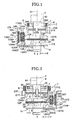
- an optical axis tilting device of a laser optical system includes a gimbal mechanism 1 (leveling mechanism) and a lens barrel 2.
- a laser light source section 3 is provided at a lower portion of the lens barrel 2, and a rotating cylinder section 4, for example, is provided at an upper portion of the lens barrel 2.
- An objective lens 5 is disposed between the laser light source section 3 and the rotating cylinder section 4 inside the lens barrel 2.
- a pentaprism (not illustrated) is disposed inside the rotating cylinder section 4.
- the laser optical system substantially includes the laser light source section 3 and the objective lens 5.
- a symbol O1 denotes an optical axis of the laser optical system. It is supposed that the direction of this optical axis O1 is Z-axis.
- the objective lens 5 is used to transform light beams emitted from the laser light source section 3 into parallel light beams, or focus the light beams to a limited distance.
- the rotating cylinder section 4 is driven by a rotary drive mechanism (not illustrated) to rotate relative to the lens barrel 2.
- the light beams emitted from the laser light source section 3 are deflected by the pentaprism, and are emitted outwards from a window (not illustrated) of the rotating cylinder section 4 while being rotated.
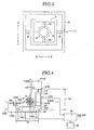
- the gimbal mechanism 1 supports the lens barrel 2 tiltably and levels a tilt frame 12 to be described in the below, and as illustrated in FIG. 2 , the gimbal mechanism 1 has a rectangular gimbal frame 7 and a rectangular gimbal frame 8.
- the gimbal frame 8 is fixed at a case (not illustrated).
- the gimbal frame 8 has a pair of turning shafts 9, 9 extending along an X-axis which is perpendicular to the Z-axis, a direction perpendicular to the X-axis and the Z-axis being Y-axis.
- the gimbal frame 7 is supported by the pair of turning shafts 9, 9, and is rotated in a YZ plane.
- the gimbal frame 7 has a pair of turning shafts 10, 10 extending along the Y-axis.
- the lens barrel 2 is supported by the pair of turning shafts 10, 10, and is rotated in an XZ plane.
- a transport mechanism frame (fixed frame) 11 is fixed to the lens barrel 2 at its lower portion. As illustrated in FIG. 4 , this transport mechanism frame 11 has an X-axis arm section 11X extending along the X-axis, and a Y-axis arm section 11Y extending along the Y-axis.
- An XZ tilting mechanism 13XZ is disposed at the X-axis arm section 11X, which relatively tilts the tilt frame 12 relative to the lens barrel 2 in the XZ plane.
- a YZ tilting device 13YZ is disposed at the Y-axis arm section 11Y, which relatively tilts the tilt frame 12 relative to the lens barrel 2 in the YZ plane.
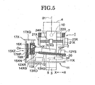
- the XZ tilting mechanism 13XZ includes a feed motor 13X, a feed screw 14X, a feed piece member (feed piece) 15X, a CCD16X as a position detection element, and a supporting frame 17X.
- the supporting frame 17X has a longitudinal wall section 17XP extending in a vertical direction, and a transversal wall section 17XQ extending in a transversal direction from the longitudinal wall section 17XP.
- the feed screw 14X is pivotally supported to be capable of rotating by the longitudinal wall section 17XQ and the X-axis arm section 11X.
- the CCD 16X is fixed to the longitudinal wall section 17XP.
- the feed piece member 15X is screwed to the feed screw 14X.
- the CCD 16X faces the feed piece member 15X.
- the X-axis feed motor 13X is fixed to the X-axis arm section 11X, and an output gear 13XG is disposed at an output shaft 13XO of the X-axis feed motor 13X.
- a rotating transmission gear 14XG is disposed at a lower portion of the feed screw 14X and is engaged with the output gear 13XG.
- the feed screw 14X is rotatably driven by the X-axis feed motor 13X, and the feed piece member 15X is driven in the vertical direction (Z-axis direction) by the rotation of the feed screw 14X.
- a LED 18X and an absolute pattern plate 19X, which are used as an absolute pattern, are disposed at the feed piece member 15X.
- the LED 18X illuminates the absolute pattern plate 19X, and by the illuminating light an absolute pattern image is projected on an imaged reception surface of the CCD16X.
- a vertical position of the feed piece member 15X depends on the absolute pattern image projected on the imaged reception surface of the CCD16X.
- a YZ tilting mechanism 13YZ has a feed motor 13Y, a feed screw 14Y, a feed piece member 15Y, a CCD 16Y as a position detection element, and a supporting frame 17Y.
- the supporting frame 17Y has a longitudinal wall section 17YP extending in the vertical direction, and a transversal wall section 17YQ extending in the transversal direction from the longitudinal wall section 17YP.
- the feed screw 14Y is pivotally supported to be capable of rotating by the transversal wall section 17YQ and Y-axis arm section 11Y.
- the CCD 16Y is fixed to the longitudinal wall section 17YP.
- the feed piece member 15Y is screwed to the feed screw 14Y.
- the CCD16Y faces the feed piece member 15Y.
- the feed motor 13Y is fixed to the Y-axis arm section 11Y, and an output gear 13YG is disposed at an output shaft 13YO of the feed motor 13Y.
- a rotating transmission gear 14YG is disposed at a lower portion of the feed screw 14Y and is engaged with the output gear 13YG.
- the feed screw 14Y is rotatably driven by the Y-axis feed motor 13Y, and the feed piece member 15Y is driven in the vertical direction by the rotation of the feed screw 14Y.
- An LED 18Y and an absolute pattern plate 19Y which are used as an absolute pattern, are disposed at the feed piece member 15Y.
- the LED18Y illuminates the absolute pattern plate 19Y, and by the illuminating light an absolute pattern image is projected on an imaged reception surface of the CCD16Y.
- a vertical position of the piece member 15Y depends on the absolute pattern image projected on the imaged reception surface of the CCD16Y.
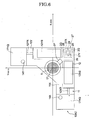
- the tilt frame 12 has an X-axis arm section 12X and a Y-axis arm section 12Y which are perpendicular to each other.
- An X-axis tilt sensor 12XS is disposed at the X-axis arm section 12X
- a Y-axis tilt sensor 12YS is disposed at the Y-axis arm section 12Y.
- An engagement rod 12XR extending along the X-axis is disposed at the X-axis arm section 12X
- an engagement rod 12YR extending along the Y-axis is disposed at the Y-axis arm section 12Y.
- a pair of engagement claws 15XN, 15XN are disposed at the feed piece member 15X, at interval in the vertical direction (refer to FIG. 1 ).
- a pair of engagement claws 15YN, 15YN are disposed at the feed piece member 15Y, at intervals in the vertical direction (as seen in FIG. 2 ).
- the pair of engagement claws 15XN, 15XN engage with the engagement rod 12XR (refer to FIG. 1 ) and the pair of engagement claws 15YN, 15YN engage with the engagement rod 12YR (refer to FIG. 2 ).
- the lens barrel 2 is provided with an arm section 2P extending towards an intersection section 12P of the X-axis arm section 12X and the Y-axis arm section 12Y, and a pivot shaft 20 extending in the vertical direction is formed at this arm section 2P.
- a conic taper concave part 12P' is formed at the intersection part 12P of the tilt frame 12.
- the pivot shaft 20 is engaged with the taper concave part 12P' (refer to FIG. 1 and FIG. 2 ).
- the tilt frame 12 is supported by the pivot shaft 20 and the pairs of engagement claws 15XN, 15XN, 15YN, 15YN, and is tilted relative to the lens barrel 2 with the pivot shaft 20 being a supporting point, in the XZ plane and the YZ plane.
- the X-axis tilt sensor 12XS and the Y-axis tilt sensor 12YS are able to detect a horizontal reference position (reference position) in which an absolute horizontal reference has been input.
- a detection output of any one of the sensors is input into a computing section (computing device) 25 illustrated in FIG. 4 .
- a pair of bearing members 21X, 21X are disposed at the gimbal frame 7, at intervals in the direction of X-axis.
- An X-axis leveling screw member 22X extending along the X-axis is rotatably supported at the pair of bearing members 21X, 21X.
- An X-axis leveling motor 23X is fixed to one of the pair of bearing members 21X, 21X.
- the X-axis leveling screw member 22X is driven to rotate by the X-axis leveling motor 23X.
- An X-axis piece member 24X is screwed to the X-axis leveling screw member 22X. This X-axis piece member 24X is fixed to the periphery of the lens barrel 2.
- a pair of bearing members 21Y, 21Y are disposed at the gimbal frame 8, at intervals in the direction of Y-axis.
- a Y-axis leveling screw member 22Y extending along the Y-axis is rotatably supported at the pair of bearing members 21Y, 21Y.
- a Y-axis leveling motor 23Y is fixed at one of the pair of bearing members 21Y, 21Y.
- the Y-axis leveling screw member 22Y is driven to rotate by the Y-axis leveling motor 23Y.
- a Y-axis piece member 24Y is screwed to the Y-axis leveling screw member 22Y. This Y-axis piece member 24Y is fixed to the gimbal frame 7.
- the X-axis leveling motor 23X When the X-axis leveling motor 23X is driven to rotate, the X-axis leveling screw member 22X is driven to rotate, whereby the X-axis piece member 24X is transferred in the direction of the X-axis, and the lens barrel 2 is tilted with the turning shafts 10, 10 being supporting points, in the XZ plane.
- the Y-axis leveling motor 23Y when the Y-axis leveling motor 23Y is driven to rotate, the Y-axis leveling screw member 22Y is driven to rotate, whereby the Y-axis piece member 24Y is transferred in the direction of the Y-axis, and the lens barrel 2 is tilted with the turning shafts 9, 9 being supporting points , in the YZ plane.
- the lens barrel 2 is set such that the optical axis O1 faces the vertical direction by a device not illustrated in the drawings.
- the tilt frame 12 is set horizontally by each of the tilting mechanisms 13XZ, 13YZ during the manufacturing process by driving the feed piece members 15X, 15Y.
- a detection position of the absolute pattern image corresponding to a horizontal position during the manufacturing process is regarded as original point positions Ox, Oy.
- An original point signal corresponding to the original point positions Ox, Oy is stored in a memory unit 26 via the computing section 25. Therefore, a vertical relationship between the optical axis O1 and the tilt frame 12 is set during the manufacturing process.
- the lens barrel 2 is set to the case through the gimbal mechanism 1.
- the optical axis O1 of the laser optical system is set at a desired angle with respect to the horizontal plane, for example, the following setting operations are performed.
- the tilt frame 12 is set to the desired angle by operating a tilting angle setting button (not illustrated), driving the feed motors 13X, 13Y, and moving the feed piece members 15X, 15Y.
- the computing section 25 detects offsets ⁇ x , ⁇ y of the feed piece members 15X,15Y deviating from the original point positions Ox, Oy, based on the position of the absolute pattern image and the original point position stored in the memory unit 26.
- the tilting angle setting button is operated until the tilting angles ⁇ x, ⁇ y of the tilt frame 12 reach the desired degrees, and at the time that the desired degrees are reached, the movement of the feed piece members 15X, 15Y are stopped.
- the tilt frame 12 as illustrated in FIG. 5 , is set to tilting angles corresponding to the tilting angles ⁇ x, ⁇ y with respect to the horizontal plane.
- the X-axis tilt sensor 12XS and the Y-axis tilt sensor 12YS output tilt signals which are proportional to the tilting angle of the tilt frame 12 with respect to the horizontal plane, to the computing section 25.
- the computing section 25 drives the X-axis leveling motor 23X and the Y-axis leveling motor 23Y so that the outputs of the X-axis tilt sensor 12XS and the Y-axis tilt sensor 12YS become "0".
- the lens barrel 2 is tilted in the XZ plane with the turning shafts 10, 10 being supporting points and tilted in the YZ plane with the turning shafts 9, 9 being supporting points, to make the tilt frame 12 to be horizontal.
- the optical axis O1 of the laser optical system is tilted ⁇ x degrees in the XZ plane and ⁇ y degrees in the YZ plane.
- the gimbal mechanism 1 functions as a leveling mechanism which levels the tilt frame 12 (i.e. adjusts the tilt frame 12 to a horizontal position).
- the tilt frame 12 is tiltable in an XZ plane which contains an X-axis and a Z-axis, and in a YZ plane which contains a Y-axis and a Z-axis, assuming that one of axes perpendicular to each other in a plane which is perpendicular to the Z-axis (optical axis O1) being the X-axis and another axis being the Y-axis.
- the actual positions of the feed piece members 15X, 15Y which tilt the tilt frame 12 are detected, therefore the tilting angle setting accuracy relative to the horizontal and the vertical of the optical axis of the laser optical system can be ensured, even the accumulated error due to the repetitive drives of the feed screws 14X, 14Y, the wear due to the repetitive drives of the feed screws 14X, 14Y, the loosening of the feed screws 14X, 14Y due to their distortion resulting from aged deterioration.
- the CCD 16X, 16Y are used to detect the position of the absolute pattern image.
- a Position Sensitive Detector PSD
- PSD Position Sensitive Detector
- a resistance element such as a slide volume as a position detection element, to detect the positions of the feed piece members 15X, 15Y.
- the absolute pattern plates 19X, 19Y are provided at the feed piece members 15X, 15Y, and the position detection elements (CCD16X, 16Y) are provided at the longitudinal wall sections 17XP, 17YP.
- the position detection elements (CCD16X, 16Y) are provided at the feed piece members 15X, 15Y, and provide the absolute patterns (LED 18X, 18Y and the absolute pattern plates 19X, 19Y) at the longitudinal wall sections 17XP, 17YP.
- the tilt frame 12 is supported by the pivot shaft 20 and is tiltable in the XZ plane with the pivot shaft 20 being the supporting point, and is tiltable in the YZ plane with the pivot shaft 20 being the supporting point.
- the tilt frame 12 is tiltable in any one of the XZ plane and the YZ plane.
- the tilt frame 12 is tilted with the pivot shaft 20 being the supporting point.
- the tilt frame 12 is supported by a gimbal mechanism 27.
- the gimbal mechanism 27 includes a gimbal frame 27X and a gimbal frame 27Y.
- the gimbal frame 27X is supported rotatably at the lens barrel 2 through a pair of turning shafts 28, 28 disposed at a pair of supporting walls 2Q, 2Q which are vertically disposed at the arm section 2P.
- the gimbal frame 27Y is supported rotatably at the lens barrel 2 through a pair of turning shafts 29, 29, and is fixed to the intersection part 12P of the tilt frame 12.
- the tilting action of the gimbal mechanism 27 is substantively same as that of the gimbal mechanism 1, and thus the detailed explanation of it is omitted.
Landscapes
- Physics & Mathematics (AREA)
- Engineering & Computer Science (AREA)
- General Physics & Mathematics (AREA)
- Radar, Positioning & Navigation (AREA)
- Remote Sensing (AREA)
- Mounting And Adjusting Of Optical Elements (AREA)
- Laser Beam Processing (AREA)
- Studio Devices (AREA)
Claims (4)
- Kippvorrichtung für eine optische Achse für ein optisches Lasersystem, die Folgendes umfasst:einen kardanischen Mechanismus (1), der einen fest angebrachten kardanischen Rahmen (8) und einen weiteren kardanischen Rahmen (7), der an dem fest angebrachten kardanischen Rahmen (8), der an einem Gehäuse fest angebracht ist, befestigt ist, um sich um eine Achse (9) drehbar zu sein, enthält;einen Objektivtubus (2), der um eine weitere Achse (10), die senkrecht zur Achse (9) ist, drehbar angeordnet ist und von dem weiteren kardanischen Rahmen (7) gestützt wird, um in zwei zueinander senkrechten Ebenen, die von den zwei zueinander senkrechten Achsen der Achse (9) und der weiteren Achse (10) gebildet werden, kippen zu können, und der einen Laserlichtquellenabschnitt (3) in einem unteren Abschnitt des Objektivtubus (2), wobei der Laserlichtquellenabschnitt (3) konfiguriert ist, um einen Laserlichtstrahl auszusenden, einen rotierenden Zylinderabschnitt (4), der konfiguriert ist, um den Laserlichtstrahl auf ein zu beleuchtendes Objekt abzulenken, und eine Objektivlinse (5), die zwischen dem Laserlichtquellenabschnitt (3) und dem rotierenden Zylinderabschnitt (4) in dem Objektivtubus (2) angeordnet ist, enthält, wobei die Objektivlinse (5) konfiguriert ist, um den Laserlichtstrahl von dem Laserlichtquellenabschnitt (3) zu dem rotierenden Zylinderabschnitt (4) zu lenken;einen fest angebrachten Rahmen (11), der im unteren Abschnitt des Obj ektivtubus (2) angebracht ist;einen Kipprahmen (12), der kippbar auf dem Objektivtubus (2) gestützt ist;einen Kippmechanismus (13XZ, 13YZ), der auf dem fest angebrachten Rahmen (11) angeordnet ist und konfiguriert ist, um den Kipprahmen (12) zu kippen;einen Kippsensor (12XS, 12YS), der an dem Kipprahmen (12) angeordnet ist und konfiguriert ist, um eine vorgegebene Referenzposition des Kipprahmens (12) zu detektieren;gekennzeichnet durch:eine Vorschubschnecke (14X, 14Y), die in dem Kippmechanismus enthalten ist und durch einen Vorschubmotor (13X, 13Y) drehbar angetrieben wird;ein Vorschubteil (15X, 15Y), das in dem Kippmechanismus enthalten ist und das durch die Vorschubschnecke hin und her bewegt wird und das mit dem Kipprahmen in Eingriff ist und den Kipprahmen in Bezug auf die Referenzposition kippt;eine Teilpositionsdetektionsvorrichtung, die in dem Kippmechanismus enthalten ist und die konfiguriert ist, um eine Position des Vorschubteils (15X, 15Y) zu ermitteln; undeinen Rechenabschnitt (25), der konfiguriert ist, um einen Kippwinkel gemäß der Position des Vorschubteils, die von der Teilpositionsdetektionsvorrichtung detektiert wurde, zu berechnen.
- Kippvorrichtung für eine optische Achse eines optischen Lasersystems nach Anspruch 1, dadurch gekennzeichnet, dass der Kipprahmen (12) durch einen Stützpunkt einer Schwenkwelle auf dem Objektivtubus (20) kippbar gestützt wird.
- Kippvorrichtung für eine optische Achse eines optischen Lasersystems nach Anspruch 1, dadurch gekennzeichnet, dass die Positionsdetektionsvorrichtung (15X, 15Y, 16X, 16Y, 18X, 18Y) ein absolutes Muster, das mit Beleuchtungslicht beleuchtet wird, und ein Positionsdetektionselement (16X, 16Y), das konfiguriert ist, um ein projiziertes Bild des absoluten Musters, das mit Beleuchtungslicht beleuchtet wird, zu empfangen, umfasst, wobei entweder das absolute Muster, oder das Positionsdetektionselement auf dem Vorschubteil (15X, 15Y) angeordnet ist und das jeweils andere auf dem fest angebrachten Rahmen (11) angeordnet ist.
- Kippvorrichtung für eine optische Achse eines optischen Lasersystems nach Anspruch 1, dadurch gekennzeichnet, dass die Teilpositionsdetektionsvorrichtung einen linearen Sensor enthält.
Applications Claiming Priority (1)
| Application Number | Priority Date | Filing Date | Title |
|---|---|---|---|
| JP2006248131A JP5054346B2 (ja) | 2006-09-13 | 2006-09-13 | 回転レーザ測量機 |
Publications (3)
| Publication Number | Publication Date |
|---|---|
| EP1901034A2 EP1901034A2 (de) | 2008-03-19 |
| EP1901034A3 EP1901034A3 (de) | 2008-06-04 |
| EP1901034B1 true EP1901034B1 (de) | 2012-05-16 |
Family
ID=38814432
Family Applications (1)
| Application Number | Title | Priority Date | Filing Date |
|---|---|---|---|
| EP07017850A Active EP1901034B1 (de) | 2006-09-13 | 2007-09-12 | Vorrichtung zur Neigung der optischen Achse eines optischen Lasersystems |
Country Status (4)
| Country | Link |
|---|---|
| US (1) | US7719778B2 (de) |
| EP (1) | EP1901034B1 (de) |
| JP (1) | JP5054346B2 (de) |
| CN (1) | CN101144717B (de) |
Families Citing this family (17)
| Publication number | Priority date | Publication date | Assignee | Title |
|---|---|---|---|---|
| KR20080063099A (ko) * | 2006-12-29 | 2008-07-03 | 파워옵틱스 주식회사 | 줌렌즈 배럴 어셈블리 |
| JP5134920B2 (ja) | 2007-11-16 | 2013-01-30 | 株式会社トプコン | 回転レーザ測量機 |
| EP2327958A1 (de) | 2009-11-26 | 2011-06-01 | Leica Geosystems AG | Rotierender Konstruktionslaser mit einem Doppelnivelliermechanismus |
| EP2522954A1 (de) * | 2011-05-11 | 2012-11-14 | Leica Geosystems AG | Neigbarer Drehkonstruktionslaser mit Gradmechanismus und Verfahren zur Bestimmung einer Position eines Gradarms des Gradmechanismus |
| JP6055179B2 (ja) * | 2011-12-19 | 2016-12-27 | 株式会社トプコン | 回転角検出装置及び測量装置 |
| TWI457541B (zh) | 2012-12-24 | 2014-10-21 | Ind Tech Res Inst | 物件表面之傾斜角的偵測方法、補償方法及其系統 |
| EP2781880B1 (de) | 2013-03-19 | 2019-01-16 | Leica Geosystems AG | Konstruktionslasersystem mit zumindest teilweise automatisch ablaufender Rekalibrierungsfunktionalität für eine Strahlhorizontierfunktionalität |
| EP2781879B1 (de) | 2013-03-19 | 2015-09-30 | Leica Geosystems AG | Konstruktionslasersystem aus Rotationslaser und Laserreceiver, mit Funktionalität zur automatischen Bestimmung der Laserreceiver-Richtung |
| JP6266937B2 (ja) | 2013-09-30 | 2018-01-24 | 株式会社トプコン | 回転レーザ出射装置およびレーザ測量システム |
| JP6144184B2 (ja) * | 2013-11-28 | 2017-06-07 | Hoya株式会社 | 屈曲撮像装置 |
| JP6831792B2 (ja) * | 2015-11-16 | 2021-02-17 | ソニーセミコンダクタソリューションズ株式会社 | 撮像装置、および、撮像システム |
| CN105466394A (zh) * | 2016-01-05 | 2016-04-06 | 上海筑邦测控科技有限公司 | 一种基于吊锤位置视频识别技术的倾角传感器 |
| JP6670355B2 (ja) * | 2018-09-26 | 2020-03-18 | 株式会社トプコン | 傾斜検出装置及び回転レーザ装置 |
| CN212135039U (zh) * | 2020-11-11 | 2020-12-11 | 常州市瑞泰光电有限公司 | 镜头驱动装置 |
| CN115072423B (zh) * | 2022-06-27 | 2025-02-14 | 无锡快仓智能科技有限公司 | 一种对接设备及对接方法 |
| CN115793180B (zh) * | 2023-01-31 | 2023-04-21 | 四川明日宇航工业有限责任公司 | 一种光传导箱及其装配工艺 |
| CN120255108A (zh) * | 2025-05-30 | 2025-07-04 | 深圳新桥自动化设备有限公司 | 多轴光学校准装置及其方法 |
Family Cites Families (7)
| Publication number | Priority date | Publication date | Assignee | Title |
|---|---|---|---|---|
| CH672839A5 (de) * | 1987-01-19 | 1989-12-29 | Ammann Lasertechnik | |
| JP3226970B2 (ja) | 1992-07-09 | 2001-11-12 | 株式会社トプコン | レーザ測量機 |
| JP3531014B2 (ja) | 1994-06-22 | 2004-05-24 | 株式会社トプコン | レーザ照準装置 |
| CH691931A5 (de) * | 1995-12-21 | 2001-11-30 | Ammann Holding Ag | Laserstrahl-Nivelliergerät sowie Verfahren zum Betrieb eines Laserstrahl-Nivelliergerätes und dazugehöriges Hilfsmittel. |
| JP4317639B2 (ja) * | 2000-03-29 | 2009-08-19 | 株式会社トプコン | レーザ測量機 |
| US6691420B2 (en) | 2002-06-03 | 2004-02-17 | Kabushiki Kaisha Audio-Technica | Laser line beam emitting apparatus having a mechanism for automatic location of a tilted laser unit holder to a desired position |
| JP4379876B2 (ja) * | 2004-09-16 | 2009-12-09 | 株式会社 ソキア・トプコン | 傾斜機能付き測量機 |
-
2006
- 2006-09-13 JP JP2006248131A patent/JP5054346B2/ja not_active Expired - Fee Related
-
2007
- 2007-09-11 US US11/900,266 patent/US7719778B2/en active Active
- 2007-09-12 EP EP07017850A patent/EP1901034B1/de active Active
- 2007-09-12 CN CN2007101544366A patent/CN101144717B/zh not_active Expired - Fee Related
Also Published As
| Publication number | Publication date |
|---|---|
| JP2008070196A (ja) | 2008-03-27 |
| US7719778B2 (en) | 2010-05-18 |
| EP1901034A2 (de) | 2008-03-19 |
| CN101144717A (zh) | 2008-03-19 |
| JP5054346B2 (ja) | 2012-10-24 |
| EP1901034A3 (de) | 2008-06-04 |
| US20080297921A1 (en) | 2008-12-04 |
| CN101144717B (zh) | 2010-06-16 |
Similar Documents
| Publication | Publication Date | Title |
|---|---|---|
| EP1901034B1 (de) | Vorrichtung zur Neigung der optischen Achse eines optischen Lasersystems | |
| EP2060870B1 (de) | Optische Achsen-Kippvorrichtung für ein Laser-optisches System | |
| EP2056066B1 (de) | Vermessungsinstrument | |
| JP6560596B2 (ja) | 測量装置 | |
| EP2564156B1 (de) | Profilmesser | |
| JP4824384B2 (ja) | レーザ測量機 | |
| CN103547886B (zh) | 用于可倾斜激光光学系统的等级机构 | |
| US8174682B2 (en) | Shape measuring instrument with light source control | |
| JP4913388B2 (ja) | レーザ測量装置 | |
| JPH1038571A (ja) | 回転レーザ装置 | |
| JP2017044550A (ja) | 測定装置 | |
| JP2017044549A (ja) | 測定装置 | |
| JP4317639B2 (ja) | レーザ測量機 | |
| JP4620428B2 (ja) | 眼科装置 | |
| JP2021063761A (ja) | 傾斜検出装置及び測量装置 | |
| JPH11230748A (ja) | 回転レーザ装置 | |
| JP4328653B2 (ja) | レーザ測定システム | |
| JP4824212B2 (ja) | レーザ照射装置 | |
| JP4267971B2 (ja) | レーザ光線照準装置及び光軸補償方法 | |
| JP4035800B2 (ja) | レーザー装置 | |
| JP2023014603A (ja) | 光電式煙感知器 | |
| JP3709245B2 (ja) | 基準平面設定装置 | |
| JPH08136257A (ja) | レーザ測量装置 |
Legal Events
| Date | Code | Title | Description |
|---|---|---|---|
| PUAI | Public reference made under article 153(3) epc to a published international application that has entered the european phase |
Free format text: ORIGINAL CODE: 0009012 |
|
| 17P | Request for examination filed |
Effective date: 20070912 |
|
| AK | Designated contracting states |
Kind code of ref document: A2 Designated state(s): AT BE BG CH CY CZ DE DK EE ES FI FR GB GR HU IE IS IT LI LT LU LV MC MT NL PL PT RO SE SI SK TR |
|
| AX | Request for extension of the european patent |
Extension state: AL BA HR MK YU |
|
| PUAL | Search report despatched |
Free format text: ORIGINAL CODE: 0009013 |
|
| AK | Designated contracting states |
Kind code of ref document: A3 Designated state(s): AT BE BG CH CY CZ DE DK EE ES FI FR GB GR HU IE IS IT LI LT LU LV MC MT NL PL PT RO SE SI SK TR |
|
| AX | Request for extension of the european patent |
Extension state: AL BA HR MK RS |
|
| 17Q | First examination report despatched |
Effective date: 20081127 |
|
| AKX | Designation fees paid |
Designated state(s): CH DE LI |
|
| GRAP | Despatch of communication of intention to grant a patent |
Free format text: ORIGINAL CODE: EPIDOSNIGR1 |
|
| GRAS | Grant fee paid |
Free format text: ORIGINAL CODE: EPIDOSNIGR3 |
|
| GRAA | (expected) grant |
Free format text: ORIGINAL CODE: 0009210 |
|
| AK | Designated contracting states |
Kind code of ref document: B1 Designated state(s): CH DE LI |
|
| REG | Reference to a national code |
Ref country code: CH Ref legal event code: EP |
|
| REG | Reference to a national code |
Ref country code: CH Ref legal event code: NV Representative=s name: BRAUNPAT BRAUN EDER AG |
|
| REG | Reference to a national code |
Ref country code: DE Ref legal event code: R096 Ref document number: 602007022572 Country of ref document: DE Effective date: 20120719 |
|
| PLBE | No opposition filed within time limit |
Free format text: ORIGINAL CODE: 0009261 |
|
| STAA | Information on the status of an ep patent application or granted ep patent |
Free format text: STATUS: NO OPPOSITION FILED WITHIN TIME LIMIT |
|
| 26N | No opposition filed |
Effective date: 20130219 |
|
| REG | Reference to a national code |
Ref country code: DE Ref legal event code: R097 Ref document number: 602007022572 Country of ref document: DE Effective date: 20130219 |
|
| REG | Reference to a national code |
Ref country code: CH Ref legal event code: PCAR Free format text: NEW ADDRESS: HOLEESTRASSE 87, 4054 BASEL (CH) |
|
| PGFP | Annual fee paid to national office [announced via postgrant information from national office to epo] |
Ref country code: DE Payment date: 20230802 Year of fee payment: 17 |
|
| PGFP | Annual fee paid to national office [announced via postgrant information from national office to epo] |
Ref country code: CH Payment date: 20231001 Year of fee payment: 17 |
|
| REG | Reference to a national code |
Ref country code: DE Ref legal event code: R119 Ref document number: 602007022572 Country of ref document: DE |
|
| REG | Reference to a national code |
Ref country code: CH Ref legal event code: PL |
|
| PG25 | Lapsed in a contracting state [announced via postgrant information from national office to epo] |
Ref country code: DE Free format text: LAPSE BECAUSE OF NON-PAYMENT OF DUE FEES Effective date: 20250401 |
|
| PG25 | Lapsed in a contracting state [announced via postgrant information from national office to epo] |
Ref country code: CH Free format text: LAPSE BECAUSE OF NON-PAYMENT OF DUE FEES Effective date: 20240930 |