EP1900932A2 - Injektor zum Einspritzen von Kraftstoff - Google Patents
Injektor zum Einspritzen von Kraftstoff Download PDFInfo
- Publication number
- EP1900932A2 EP1900932A2 EP07112398A EP07112398A EP1900932A2 EP 1900932 A2 EP1900932 A2 EP 1900932A2 EP 07112398 A EP07112398 A EP 07112398A EP 07112398 A EP07112398 A EP 07112398A EP 1900932 A2 EP1900932 A2 EP 1900932A2
- Authority
- EP
- European Patent Office
- Prior art keywords
- extension
- actuator
- shim
- actuator head
- coupler piston
- Prior art date
- Legal status (The legal status is an assumption and is not a legal conclusion. Google has not performed a legal analysis and makes no representation as to the accuracy of the status listed.)
- Granted
Links
Images


Classifications
-
- F—MECHANICAL ENGINEERING; LIGHTING; HEATING; WEAPONS; BLASTING
- F02—COMBUSTION ENGINES; HOT-GAS OR COMBUSTION-PRODUCT ENGINE PLANTS
- F02M—SUPPLYING COMBUSTION ENGINES IN GENERAL WITH COMBUSTIBLE MIXTURES OR CONSTITUENTS THEREOF
- F02M47/00—Fuel-injection apparatus operated cyclically with fuel-injection valves actuated by fluid pressure
- F02M47/02—Fuel-injection apparatus operated cyclically with fuel-injection valves actuated by fluid pressure of accumulator-injector type, i.e. having fuel pressure of accumulator tending to open, and fuel pressure in other chamber tending to close, injection valves and having means for periodically releasing that closing pressure
- F02M47/027—Electrically actuated valves draining the chamber to release the closing pressure
-
- F—MECHANICAL ENGINEERING; LIGHTING; HEATING; WEAPONS; BLASTING
- F02—COMBUSTION ENGINES; HOT-GAS OR COMBUSTION-PRODUCT ENGINE PLANTS
- F02M—SUPPLYING COMBUSTION ENGINES IN GENERAL WITH COMBUSTIBLE MIXTURES OR CONSTITUENTS THEREOF
- F02M61/00—Fuel-injectors not provided for in groups F02M39/00 - F02M57/00 or F02M67/00
- F02M61/16—Details not provided for in, or of interest apart from, the apparatus of groups F02M61/02 - F02M61/14
- F02M61/168—Assembling; Disassembling; Manufacturing; Adjusting
-
- F—MECHANICAL ENGINEERING; LIGHTING; HEATING; WEAPONS; BLASTING
- F02—COMBUSTION ENGINES; HOT-GAS OR COMBUSTION-PRODUCT ENGINE PLANTS
- F02M—SUPPLYING COMBUSTION ENGINES IN GENERAL WITH COMBUSTIBLE MIXTURES OR CONSTITUENTS THEREOF
- F02M63/00—Other fuel-injection apparatus having pertinent characteristics not provided for in groups F02M39/00 - F02M57/00 or F02M67/00; Details, component parts, or accessories of fuel-injection apparatus, not provided for in, or of interest apart from, the apparatus of groups F02M39/00 - F02M61/00 or F02M67/00; Combination of fuel pump with other devices, e.g. lubricating oil pump
- F02M63/0012—Valves
- F02M63/0014—Valves characterised by the valve actuating means
- F02M63/0015—Valves characterised by the valve actuating means electrical, e.g. using solenoid
- F02M63/0026—Valves characterised by the valve actuating means electrical, e.g. using solenoid using piezoelectric or magnetostrictive actuators
-
- F—MECHANICAL ENGINEERING; LIGHTING; HEATING; WEAPONS; BLASTING
- F02—COMBUSTION ENGINES; HOT-GAS OR COMBUSTION-PRODUCT ENGINE PLANTS
- F02M—SUPPLYING COMBUSTION ENGINES IN GENERAL WITH COMBUSTIBLE MIXTURES OR CONSTITUENTS THEREOF
- F02M2200/00—Details of fuel-injection apparatus, not otherwise provided for
- F02M2200/70—Linkage between actuator and actuated element, e.g. between piezoelectric actuator and needle valve or pump plunger
- F02M2200/703—Linkage between actuator and actuated element, e.g. between piezoelectric actuator and needle valve or pump plunger hydraulic
-
- F—MECHANICAL ENGINEERING; LIGHTING; HEATING; WEAPONS; BLASTING
- F02—COMBUSTION ENGINES; HOT-GAS OR COMBUSTION-PRODUCT ENGINE PLANTS
- F02M—SUPPLYING COMBUSTION ENGINES IN GENERAL WITH COMBUSTIBLE MIXTURES OR CONSTITUENTS THEREOF
- F02M2200/00—Details of fuel-injection apparatus, not otherwise provided for
- F02M2200/80—Fuel injection apparatus manufacture, repair or assembly
- F02M2200/8015—Provisions for assembly of fuel injection apparatus in a certain orientation, e.g. markings, notches or specially shaped sleeves other than a clip
Definitions
- the invention relates to an injector for injecting fuel into a combustion chamber of an internal combustion engine according to the preamble of claim 1.
- fuel injectors are used. These generally include an actuator operated control valve. Magnetic actuators or piezoactuators are usually used as actuators. Due to the very small strokes, even slight deviations in the dimensions of the individual components of the injector lead to malfunction.
- a coupler piston between the piezoelectric actuator and the control valve is connected.
- the coupler piston translates the stroke of the actuator.
- a shim is added between the piezoelectric actuator and the coupler piston. The thickness of the shim is chosen so that the length tolerances are compensated.
- a bore in two different diameters is performed in the shim. On the side with a smaller diameter, the bore is followed by a dome-shaped enlargement. With correct installation of the dial, an extension on the actuator head of the piezoelectric actuator is located on the dome-shaped extension.
- An extension formed on the coupler piston is received in the larger diameter bore.
- the shim is located on an extension on the coupler piston. However, if the shim is inserted the wrong way round, the extension on the coupler piston abuts the dome-shaped enlargement since it can not be received by the smaller diameter bore. At the same time, the extension is also located on the actuator head of the piezoelectric actuator on the dial. The shim is thus not on the coupler piston and the distance between the coupler piston and actuator head is larger than a given dimension. This indicates that the dial has been installed the wrong way round.
- the shim is punched out first, sanded smooth in a next step by vibratory grinding, in the ground disc, the bore and the dome-shaped depression are lowered, which forms a Crugewulst on one side of the disc. Subsequently, the shim is hardened and abraded the Crugewulst. The classification of the shim is done by finish grinding and subsequent finishing grinding for smoothing. Finally, the shim is tested and classified. Since the dome-shaped recess can be damaged during slide grinding, a visual inspection of each individual dial is required.
- an injection valve member for releasing or closing at least one injection port is actuated by an actuator-operated control valve.
- the actuator comprises an actuator head which acts on a coupler piston.
- a shim is arranged between the actuator head and the coupler piston, wherein an extension is formed on the actuator head, which is received in a recess of the shim.
- a bead is formed such that the distance between the actuator head and the coupler piston deviates from a predetermined extent in an incorrect positioning of the shim.
- the shim used according to the invention can be produced with less complexity than the shim according to the prior art.
- the required bead arises when lowering the recess. Unlike the shims known from the prior art, it is not necessary to grind the bead formed when the recess is lowered. Another advantage is that a visual inspection is no longer necessary, since damage in the region of the depression can no longer occur.
- the punching of the dial can be done with a solid stamp.
- the bead is preferably formed so that it encloses the recess in the shim. If the shim is correctly mounted, then the bead surrounds the extension on the actuator head. Incorrect installation of the shim causes the bead to rest on the coupler piston. This results in that the distance between the coupler piston and the extension on the actuator is greater than a predetermined amount. From this it can be seen that a wrong assembly has taken place.
- the shim is preferably penetrated by a bore, wherein an extension of the coupler piston is received in the bore.
- the actuator and the coupler piston are preferably aligned axially aligned with each other. Therefore, the bore preferably opens into the recess on the dial, in which the extension is received on the actuator head.
- the diameter of the extension on the coupler piston is preferably smaller than that Diameter of the extension on the actuator head.
- the diameter of the bore can be made smaller than the diameter of the extension on the actuator head.
- a plate-shaped extension is generally formed, on which the shim rests. If the shim is correctly mounted, the shim with its flat face is located on the extension on the coupler piston. If the shim is mounted incorrectly, the bead rests on the plate-shaped enlargement and causes the actual dimension of the distance between the actuator head and the coupler piston to deviate from a predetermined setpoint. This can be the wrong installation of the dial recognize.
- the recess in the shim, in which the extension is received on the actuator head is preferably formed dome-shaped.
- the extension on the actuator head preferably ends with a spherical layer, so that the spherical layer rests flush in the dome-shaped depression. Through the dome-shaped depression a gimbal suspension of the actuator head in the dial is possible.
- the bead is made by embossing the recess in the dial.
- embossing of the depression and the consequent emergence of the bead it is also possible to produce the depression, for example, by a machining process.
- the bead can be produced, for example, by a cutting process on the end face of the shim. It is also possible to produce the bead by material application, for example by welding.
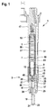
- FIG. 1 shows a fuel injector with a dial.
- An injector 1 comprises a control valve 3, which is confirmed via an actuator 5.
- the actuator 5 is a piezoelectric actuator.
- the actuator 5 is connected to an actuator head 7, which acts on a coupler piston 9.
- a booster piston 15 defines the booster chamber 13 the translator piston 15, the stroke of the actuator 5 is hydraulically translated.
- the translation of the stroke is dependent on the diameter of the coupler piston 9 and the diameter of the booster piston 15.
- a piezoelectric actuator as the actuator 5 so a smaller piezoelectric actuator can be used.
- an injection valve member 19 is driven.
- the injection valve member 19 is at least an injection port 21 free or closes this.
- the injection valve member 19 in a seat 23 in a lower housing part 25 can be adjusted.
- the injection valve member 19 opens with an end face 27 in a control chamber 29.
- the control chamber 29 is further limited by a ring member 31 and an intermediate disc 33.
- a biting edge 35 is formed, which is placed against the washer 33.
- the required force is applied by a spring element 37 which acts on the ring element 31.
- the spring element 37 acts on a shoulder 39 on the injection valve member 19.
- the required spring force is adjusted by an adjustment ring 41.
- the spring force of the spring element 37 is dependent on the height of the adjusting ring 41.
- the spring element 37 is e.g. a trained as a spiral spring compression spring.
- a valve disc 43 connects.
- a valve seat 45 of the control valve 3 is formed.
- an upper housing part 47 connects.
- the our housing part 25, the intermediate disc 33, the valve disc 43 and the upper housing part 47 are connected by a nozzle lock nut 49 with each other.
- the actuator space 51 is e.g. designed as a blind hole in the upper housing 47.
- the actuator 5 is received in the actuator chamber 51 between an actuator base 53 and the actuator head 7.
- the actuator 5 is enclosed by a sleeve 55.
- a stable attachment of the actuator 5 in the sleeve 55 is achieved in that the actuator is cast using potting compound 57 in the sleeve. So that no fuel can penetrate into the sleeve 55, the sleeve in the region of the actuator head 7 is closed by a diaphragm 59.
- the actuator base 53, the actuator 5 and the actuator head 7 comprising, shown, is between the actuator head 7 and the coupler piston 9, a shim 61 added.
- Figure 2 shows an enlarged view of the actuator head, coupler piston and shim with proper mounting of the shim.
- an extension 71 is formed, which is placed in a recess 73 in the dial 61.
- the recess 73 is formed dome-shaped.
- the extension 71 runs in the form of a spherical layer 75, so that the extension 71 rests flush on the dome-shaped recess 73.
- an extension 77 is formed, which is received in a bore 79 which is formed in the dial 61.
- the diameter of the bore 79 is preferably selected so that the dial 61 can be set without play on the extension 7 on the coupler piston 9.
- the dial 61 When properly mounted, the dial 61 rests with a flat ground end face 81 on an extension 83 on the coupler piston 9.
- a bead 85 is formed on the adjusting disk 61.
- the bead 85 encloses the recess 73 in the dial 61 and thus, when properly mounted, also the projection 71 on the actuator head 7.
- the bead 85 is formed e.g. by lowering the recess 73 in the dial 61st
- a predetermined desired distance s between an upper end face 87 of the extension 83 on the coupler piston 9, on which the shim 61 rests, and a shoulder 89 on the actuator head 7 is set.
- the setting of the nominal distance s takes place via the height h of the adjusting disk 61.
- the bead 85 formed on the adjusting disk 61 rests on the upper end face 87 of the extension 83 on the coupler piston 9.
- the extension 77 on the coupler piston 9 protrudes through the recess 73 into the bore 79, which is formed in the dial 61.
- the diameter of the extension 77 on the coupler piston is smaller than the diameter of the extension 71 on the actuator head 7 and the diameter of the Borhung 79 is therefore smaller than the diameter of the extension 71 on the actuator head 7, the extension 71 is not inserted into the bore 79 become. In case of incorrect installation of the dial 61 of the extension 71 is thus on the dial 61.
- a chamfer 91 is formed on the bore 79 in the dial 61 on the side opposite the recess 73.
- extension 71 Depending on the diameter of the extension 71, it is possible for the extension 71 to rest on the actuator head 7 with the ball layer 75 on the chamfer 91 if it is mounted incorrectly.
- the bead 85 rests on the extension 83 on the coupler piston 9 and the extension 71 on the actuator head 7 can not be inserted into the bore 79, the distance between the upper end surface 87 on the extension 83 of the coupler piston 9 and the shoulder 89 on the actuator head 7 is greater than the desired distance s.
- the distance between the shoulder 89 on the actuator head 7 and the upper end face 87 of the extension 83 on the coupler piston 9 reaches a value of s + x.
- x means the difference between the actual distance between the shoulder 89 and the upper end face 87 and the desired distance s.
Abstract
Description
- Die Erfindung geht aus von einem Injektor zum Einspritzen von Kraftstoff in einen Brennraum einer Verbrennungskraftmaschine gemäß dem Oberbegriff des Anspruchs 1.
- Zum Einspritzen von Kraftstoff in direkt einspritzende Verbrennungskraftmaschinen werden Kraftstoffinjektoren eingesetzt. Diese umfassen im allgemeinen ein aktorbetätigtes Steuerventil. Als Aktoren werden üblicherweise Magnetaktoren oder Piezoaktoren eingesetzt. Aufgrund der sehr kleinen Hübe führen bereits geringe Abweichungen in den Abmaßen der einzelnen Bauteile des Injektors zu Fehlfunktionen.
- Bei Kraftstoffinjektoren, die mit einem Piezoaktor betätigt werden, ist üblicherweise ein Kopplerkolben zwischen den Piezoaktor und das Steuerventil geschaltet. Durch den Kopplerkolben wird der Hub des Aktors übersetzt. Um Längentoleranzen zwischen dem Piezoaktor und dem Kopplerkolben auszugleichen, ist zwischen dem Piezoaktor und dem Kopplerkolben eine Einstellscheibe aufgenommen. Die Dicke der Einstellscheibe wird dabei so gewählt, dass die Längentoleranzen ausgeglichen werden. Bei den Einstellscheiben, wie sie nach dem Stand der Technik eingesetzt werden, ist in der Einstellscheibe eine Bohrung in zwei verschiedenen Durchmessern ausgeführt. Auf der Seite mit kleinerem Durchmesser schließt sich an die Bohrung eine kalottenförmige Erweiterung an. Bei korrekter Montage der Einstellscheibe liegt ein Fortsatz am Aktorkopf des Piezoaktors an der kalottenförmigen Erweiterung an. Ein am Kopplerkolben ausgebildeter Fortsatz ist in der Bohrung mit dem größeren Durchmesser aufgenommen. Die Einstellscheibe liegt auf einer Erweiterung am Kopplerkolben auf. Wenn die Einstellscheibe jedoch falsch herum eingesetzt wird, liegt der Fortsatz am Kopplerkolben an der kalottenförmigen Erweiterung an, da dieser nicht von der Bohrung mit dem geringeren Durchmesser aufgenommen werden kann. Gleichzeitig liegt auch der Fortsatz am Aktorkopf des Piezoaktors auf der Einstellscheibe auf. Die Einstellscheibe liegt somit nicht auf dem Kopplerkolben auf und der Abstand zwischen Kopplerkolben und Aktorkopf ist größer als ein vorgegebenes Maß. Daran lässt sich erkennen, dass die Einstellscheibe falsch herum eingebaut worden ist.
- Nachteil der Einstellscheibe mit einer Bohrung in zwei verschiedenen Durchmessern und der kalottenförmigen Erweiterung ist jedoch, dass diese durch ein aufwendiges Herstellverfahren hergestellt werden muss. Hierbei wird die Einstellscheibe zunächst ausgestanzt, in einem nächsten Schritt durch Gleitschleifen glatt geschliffen, in die geschliffene Scheibe werden die Bohrung und die kalottenförmige Vertiefung gesenkt, wodurch sich auf einer Seite der Scheibe eine Prägewulst ausbildet. Daran anschließend wird die Einstellscheibe gehärtet und der Prägewulst abgeschliffen. Die Klassierung der Einstellscheibe erfolgt durch Fertigschleifen und anschließendes Gleitschleifen zum Glätten. Abschließend wird die Einstellscheibe geprüft und klassifiziert. Da die kalottenförmige Vertiefung beim Gleitschleifung beschädigt werden kann, ist eine Sichtprüfung jeder einzelnen Einstellscheibe erforderlich.
- Bei einem erfindungsgemäß ausgebildeten Injektor zum Einspitzen von Kraftstoff in einen Brennraum einer Verbrennungskraftmaschine wird ein Einspritzventilglied zum Freigeben oder Verschließen mindestens einer Einspritzöffnung durch ein aktorbetätigtes Steuerventil angesteuert. Der Aktor umfasst einen Aktorkopf, der auf einen Kopplerkolben wirkt. Zum Ausgleich von Längentoleranzen ist zwischen dem Aktorkopf und dem Kopplerkolben eine Einstellscheibe angeordnet, wobei am Aktorkopf ein Fortsatz ausgebildet ist, der in einer Vertiefung der Einstellscheibe aufgenommen ist. An der Einstellscheibe ist eine Wulst derart ausgebildet, dass bei einer falschen Positionierung der Einstellscheibe das Abstandsmaß zwischen Aktorkopf und Kopplerkolben von einem vorgegebenen Maß abweicht.
- Die erfindungsgemäß eingesetzte Einstellscheibe, zum Ausgleich von Längentoleranzen, lässt sich aufwendig weniger herstellen als die Einstellscheibe gemäß dem Stand der Technik. Die erforderliche Wulst entsteht beim Senken der Vertiefung. Anders als bei den aus dem Stand der Technik bekannten Einstellscheiben ist es nicht notwendig, die Wulst, die beim Senken der Vertiefung entstanden ist, abzuschleifen. Ein weiterer Vorteil ist auch, dass eine Sichtprüfung nicht mehr erforderlich ist, da eine Beschädigung im Bereich der Vertiefung nicht mehr auftreten kann. Zudem kann das Stanzen der Einstellscheibe mit einem massiveren Stempel erfolgen.
Die Wulst ist vorzugsweise so ausgebildet, dass diese die Vertiefung in der Einstellscheibe umschließt. Bei richtiger Montage der Einstellscheibe umschließt dann die Wulst den Fortsatz am Aktorkopf. Bei falscher Montage der Einstellscheibe führt dies dazu, dass die Wulst auf dem Kopplerkolben aufliegt. Dies führt dazu, dass der Abstand zwischen dem Kopplerkolben und dem Fortsatz am Aktor größer ist als ein vorgegebenes Maß. Hieran lässt sich erkennen, dass eine falsche Montage erfolgt ist. - Um zu vermeiden, dass bei der Montage die Einstellscheibe auf dem Kopplerkolben verrutschen kann, ist die Einstellscheibe vorzugsweise von einer Bohrung durchsetzt, wobei in der Bohrung ein Fortsatz des Kopplerkolbens aufgenommen ist.
- Damit die Einstellscheibe beim Betrieb des Injektors nicht verkanten kann, sind der Aktor und der Kopplerkolben vorzugsweise axial fluchtend zueinander ausgerichtet. Die Bohrung mündet daher vorzugsweise in der Vertiefung an der Einstellscheibe, in der der Fortsatz am Aktorkopf aufgenommen ist.
- Damit bei einer falschen Montage der Einstellscheibe der Fortsatz am Aktorkopf nicht in die Bohrung in der Einstellscheibe eingeführt werden kann, um hierdurch eine deutliche Abweichung des Ist-Maßes vom vorgegebenen Soll-Maß zu erreichen, ist der Durchmesser des Fortsatzes am Kopplerkolben vorzugsweise kleiner als der Durchmesser des Fortsatzes am Aktorkopf. Hierdurch lässt sich auch der Durchmesser der Bohrung kleiner fertigen als der Durchmesser des Fortsatzes am Aktorkopf.
- Am Kopplerkolben ist im allgemeinen eine tellerförmige Erweiterung ausgebildet, auf der die Einstellscheibe aufliegt. Bei richtiger Montage der Einstellscheibe liegt die Einstellscheibe mit ihrer flachen Stirnseite auf der Erweiterung am Kopplerkolben auf. Bei falscher Montage der Einstellscheibe liegt die Wulst auf der tellerförmigen Erweiterung auf und führt dazu, dass das Ist-Maß des Abstandes von Aktorkopf und Kopplerkolben von einem vorgegebenen Soll-Maß abweicht. Hieran lässt sich die falsche Montage der Einstellscheibe erkennen.
- Die Vertiefung in der Einstellscheibe, in der der Fortsatz am Aktorkopf aufgenommen ist, ist vorzugsweise kalottenförmig ausgebildet. Der Fortsatz am Aktorkopf schließt vorzugsweise mit einer Kugelschicht ab, so dass die Kugelschicht bündig in der kalottenförmigen Vertiefung anliegt. Durch die kalottenförmige Vertiefung ist eine kardanische Aufhängung des Aktorkopfes in der Einstellscheibe möglich.
- Im allgemeinen wird die Wulst durch Prägen der Vertiefung in der Einstellscheibe hergestellt. Neben dem Prägen der Vertiefung und der daraus folgenden Entstehung der Wulst ist es jedoch auch möglich, die Vertiefung z.B. durch ein spanendes Verfahren herzustellen. In diesem Fall lässt sich die Wulst z.B. auch durch ein spanabhebendes Verfahren an der Stirnfläche der Einstellscheibe herstellen. Auch ist es möglich, die Wulst durch Materialauftrag z.B. durch Schweißen herzustellen.
- Ausführungsbeispiele der Erfindung sind in den Zeichnungen dargestellt und in der nachfolgenden Beschreibung näher erläutert.
-
- Figur 1
- einen Kraftstoffinjektor mit Einstellscheibe,
- Figur 2
- eine vergrößerte Darstellung von Aktorkopf, Kopplerkolben und Einstellscheibe mit korrekter Montage der Einstellscheibe,
- Figur 3
- eine vergrößerte Darstellung von Aktorkopf, Kopplerkolben und Einstellscheibe mit falscher Montage der Einstellscheibe.
- In Figur 1 ist ein Kraftstoffinjektor mit einer Einstellscheibe dargestellt.
- Ein Injektor 1 umfasst ein Steuerventil 3, welches über einen Aktor 5 bestätigt wird. Bei dem in Figur 1 dargestellten Kraftstoffinjektor ist der Aktor 5 ein Piezoaktor. Der Aktor 5 ist mit einem Aktorkopf 7 verbunden, der auf einen Kopplerkolben 9 wirkt. Mit seiner dem Aktorkopf 7 abgewandten Stirnfläche 11 mündet der Kopplerkolben 9 in einen Übersetzerraum 13. An der dem Kopplerkolben 9 gegenüber liegenden Seite begrenzt ein Übersetzerkolben 15 den Übersetzerraum 13. Der Übersetzerkolben 15 wirkt auf ein Ventilglied 17 des Steuerventils 3. Durch den Kopplerkolben 9 und den Übersetzerkolben 15 wird der Hub des Aktors 5 hydraulisch übersetzt. Die Übersetzung des Hubes ist dabei abhängig vom Durchmesser des Kopplerkolbens 9 und dem Durchmesser des Übersetzerkolbens 15. Bei einem kleineren Durchmesser des Übersetzerkolbens 15 ist der Hub, den dieser zurücklegt, größer als der Hub des Kopplerkolbens 9. Hierdurch ist ein kleinerer Hub des Aktors 5 erforderlich. Bei Verwendung eines Piezoaktors als Aktor 5 kann so ein kleinerer Piezoaktor eingesetzt werden. Es ist weniger Bauraum für den Injektor 1 erforderlich. Über das Steuerventil 3 wird ein Einspritzventilglied 19 angesteuert. Das Einspritzventilglied 19 gibt mindestens eine Einspritzöffnung 21 frei oder verschließt diese. Hierzu ist das Einspritzventilglied 19 in einen Sitz 23 in einem unteren Gehäuseteil 25 stellbar.
- Das Einspritzventilglied 19 mündet mit einer Stirnfläche 27 in einen Steuerraum 29. Der Steuerraum 29 wird weiterhin von einem Ringelement 31 und einer Zwischenscheibe 33 begrenzt. Am Ringelement 31 ist eine Beißkante 35 ausgebildet, die gegen die Zwischenscheibe 33 gestellt ist. Hierdurch wird eine flüssigkeitsdichte Verbindung von Ringelement 31 und Zwischenscheibe 33 erzielt. Die erforderliche Kraft wird durch ein Federelement 37, das auf das Ringelement 31 wirkt, aufgebracht. Mit der anderen Seite wirkt das Federelement 37 auf eine Schulter 39 am Einspritzventilglied 19. Die erforderliche Federkraft wird durch einen Einstellring 41 eingestellt. Die Federkraft des Federelementes 37 ist dabei abhängig von der Höhe des Einstellringes 41. Das Federelement 37 ist z.B. eine als Spiralfeder ausgebildete Druckfeder.
- An die Zwischenscheibe 33 schließt sich eine Ventilscheibe 43 an. In der Ventilscheibe 43 ist ein Ventilsitz 45 des Steuerventils 3 ausgebildet. An die Ventilscheibe 43 schließt sich ein oberes Gehäuseteil 47 an. Das unsere Gehäuseteil 25, die Zwischenscheibe 33, die Ventilscheibe 43 und das obere Gehäuseteil 47 sind durch eine Düsenspannmutter 49 miteinander verbunden.
- Der Aktor 5, in der hier dargestellten Ausführungsform ein Piezoaktor, ist in einem Aktorraum 51 aufgenommen. Der Aktorraum 51 ist z.B. als Sacklochbohrung im oberen Gehäuseteil 47 ausgeführt. Der Aktor 5 ist im Aktorraum 51 zwischen einem Aktorfuß 53 und dem Aktorkopf 7 aufgenommen. Um den Aktor 5 gegen Kraftstoff abzudichten, ist der Aktor 5 von einer Hülse 55 umschlossen. Eine stabile Befestigung des Aktors 5 in der Hülse 55 wird dadurch erreicht, dass der Aktor mithilfe von Vergussmasse 57 in die Hülse eingegossen ist. Damit kein Kraftstoff in die Hülse 55 eindringen kann, ist die Hülse im Bereich des Aktorkopfes 7 durch eine Membran 59 verschlossen.
- Zum Ausgleich von Längentoleranzen, die sich z.B. bei der Bohrung des Aktorraumes 51 und durch das Aktormodul, den Aktorfuß 53, den Aktor 5 und den Aktorkopf 7 umfassend, ergeben, ist zwischen dem Aktorkopf 7 und dem Kopplerkolben 9 eine Einstellscheibe 61 aufgenommen.
- Figur 2 zeigt eine vergrößerte Darstellung von Aktorkopf, Kopplerkolben und Einstellscheibe bei richtiger Montage der Einstellscheibe.
Am Aktorkopf 7 ist ein Fortsatz 71 ausgebildet, der in eine Vertiefung 73 in der Einstellscheibe 61 gestellt ist. Die Vertiefung 73 ist kalottenförmig ausgebildet. Der Fortsatz 71 läuft in Form einer Kugelschicht 75 aus, so dass der Fortsatz 71 bündig an der kalottenförmigen Vertiefung 73 anliegt. - Am Kopplerkolben 9 ist ein Fortsatz 77 ausgebildet, der in einer Bohrung 79, die in der Einstellscheibe 61 ausgebildet ist, aufgenommen ist. Der Durchmesser der Bohrung 79 wird vorzugsweise so gewählt, dass die Einstellscheibe 61 spielfrei über den Fortsatz 7 am Kopplerkolben 9 gesetzt werden kann.
- Bei richtiger Montage liegt die Einstellscheibe 61 mit einer plangeschliffenen Stirnfläche 81 auf einer Erweiterung 83 am Kopplerkolben 9 auf.
- Erfindungsgemäß ist an der Einstellscheibe 61 eine Wulst 85 ausgebildet. Die Wulst 85 umschließt die Vertiefung 73 in der Einstellscheibe 61 und somit bei richtiger Montage auch den Fortsatz 71 am Aktorkopf 7. Die Wulst 85 entsteht dabei z.B. durch Senken der Vertiefung 73 in die Einstellscheibe 61.
- Durch die Einstellscheibe 61 wird ein vorgegebener Soll-Abstand s zwischen einer oberen Stirnfläche 87 der Erweiterung 83 am Kopplerkolben 9, auf der die Einstellscheibe 61 aufliegt, und einer Schulter 89 am Aktorkopf 7 eingestellt. Die Einstellung des Soll-Abstandes s erfolgt dabei über die Höhe h der Einstellscheibe 61.
- In Figur 3 ist ein Aktorkopf, ein Kopplerkolben und eine Einstellscheibe dargestellt bei falscher Montage der Einstellscheibe.
- Bei falscher Montage der Einstellscheibe 61 liegt die an der Einstellscheibe 61 ausgebildete Wulst 85 auf der oberen Stirnfläche 87 der Erweiterung 83 am Kopplerkolben 9 auf. Der Fortsatz 77 am Kopplerkolben 9 ragt durch die Vertiefung 73 in die Bohrung 79, die in der Einstellscheibe 61 ausgebildet ist.
- Da erfindungsgemäß der Durchmesser des Fortsatzes 77 am Kopplerkolben kleiner ist als der Durchmesser des Fortsatzes 71 am Aktorkopf 7 und auch der Durchmesser der Borhung 79 demzufolge kleiner ist als der Durchmesser des Fortsatzes 71 am Aktorkopf 7, kann der Fortsatz 71 nicht in die Bohrung 79 eingeführt werden. Bei falscher Montage der Einstellscheibe 61 liegt der Fortsatz 71 somit auf der Einstellscheibe 61 auf.
- In der in Figur 2 und 3 dargestellten Ausführungsform ist an der Bohrung 79 in der Einstellscheibe 61 an der der Vertiefung 73 gegenüber liegenden Seite eine Fase 91 ausgebildet.
- Abhängig vom Durchmesser des Fortsatzes 71 ist es möglich, dass der Fortsatz 71 am Aktorkopf 7 mit der Kugelschicht 75 bei falscher Montage an der Fase 91 anliegt.
- Da bei falscher Montage der Einstellscheibe 61 die Wulst 85 auf der Erweiterung 83 am Kopplerkolben 9 aufliegt und der Fortsatz 71 am Aktorkopf 7 nicht in die Bohrung 79 eingeführt werden kann, ist der Abstand zwischen der oberen Stirnfläche 87 an der Erweiterung 83 des Kopplerkolbens 9 und der Schulter 89 am Aktorkopf 7 größer als der Soll-Abstand s. Der Abstand zwischen der Schulter 89 am Aktorkopf 7 und der oberen Stirnfläche 87 der Erweiterung 83 am Kopplerkolben 9 erreicht einen Wert von s+x. Dabei bedeutet x die Differenz zwischen dem tatsächlichen Abstand zwischen der Schulter 89 und der oberen Stirnfläche 87 und dem Soll-Abstand s. Bei falscher Montage nimmt der Abstand zwischen der Schulter 89 am Aktorkopf 7 und der oberen Stirnfläche 87 der Erweiterung 83 am Kopplerkolben 9 den Wert s+x ein. An diesem zu großen Wert lässt sich die falsche Montage der Einstellscheibe 61. erkennen.
Claims (9)
- Injektor zum Einspritzen von Kraftstoff in einen Brennraum einer Verbrennungskraftmaschine, bei dem ein Einspritzventilglied (19) zum Freigeben oder Verschließen mindestens einer Einspritzöffnung (21) durch ein aktorbetätigtes Steuerventil (3) angesteuert wird, wobei der Aktor (5) einen Aktorkopf (7) umfasst, der auf einen Kopplerkolben (9) wirkt, und zum Ausgleich von Längentoleranzen eine Einstellscheibe (61) zwischen dem Aktorkopf (7) und dem Kopplerkolben (9) angeordnet ist, wobei am Aktorkopf (7) ein Fortsatz (71) ausgebildet ist, der in einer Vertiefung (73) in der Einstellscheibe (61) aufgenommen ist, dadurch gekennzeichnet, dass an der Einstellscheibe (61) eine Wulst (85) derart ausgebildet ist, dass bei einer falschen Positionierung der Einstellscheibe (61) das Abstandsmaß zwischen Aktorkopf (7) und Kopplerkolben (9) von einem vorgegebenen Maß abweicht.
- Injektor nach Anspruch 1, dadurch gekennzeichnet, dass die Wulst (85) die Vertiefung (73) in der Einstellscheibe (61) umschließt.
- Injektor nach Anspruch 1 oder 2, dadurch gekennzeichnet, dass bei richtiger Montage der Einstellscheibe (61) zwischen Aktorkopf (7) und Kopplerkolben (9) die Wulst (85) den Fortsatz (71) am Aktorkopf (7) umschließt.
- Injektor nach einem der Ansprüche 1 bis 3, dadurch gekennzeichnet, dass die Einstellscheibe (61) von einer Bohrung (79) durchsetzt ist, wobei in der Bohrung (79) ein Fortsatz (77) des Kopplerkolbens (9) aufgenommen ist.
- Injektor nach Anspruch 4, dadurch gekennzeichnet, dass die Bohrung (79) in der Vertiefung (73) in der Einstellscheibe (61) mündet, in der der Fortsatz (71) am Aktorkopf (7) aufgenommen ist.
- Injektor nach Anspruch 4 oder 5, dadurch gekennzeichnet, dass der Durchmesser des Fortsatzes (77) am Kopplerkolben (9) kleiner ist als der Durchmesser des Fortsatzes (71) am Aktorkopf (7).
- Injektor nach einem der Ansprüche 1 bis 6, dadurch gekennzeichnet, dass am Kopplerkolben (9) eine tellerförmige Erweiterung (83) ausgebildet ist, auf der die Einstellscheibe (61) aufliegt.
- Injektor nach einem der Ansprüche 1 bis 7, dadurch gekennzeichnet, dass die Vertiefung (73) in der Einstellscheibe (61), in der der Fortsatz (71) am Aktorkopf (7) aufgenommen ist, kalottenförmig ausgebildet ist und der Fortsatz (71) am Aktorkopf (7) mit einer Kugelschicht (75) abschließt, wobei die Kugelschicht (75) bündig an der kalottenförmigen Vertiefung (73) anliegt.
- Injektor nach einem der Ansprüche 1 bis 8, dadurch gekennzeichnet, dass die Wulst (85) durch Prägen der Vertiefung (73) in der Einstellscheibe (61) hergestellt wird.
Applications Claiming Priority (1)
| Application Number | Priority Date | Filing Date | Title |
|---|---|---|---|
| DE102006042601A DE102006042601A1 (de) | 2006-09-11 | 2006-09-11 | Injektor zum Einspritzen von Kraftstoff |
Publications (3)
| Publication Number | Publication Date |
|---|---|
| EP1900932A2 true EP1900932A2 (de) | 2008-03-19 |
| EP1900932A3 EP1900932A3 (de) | 2009-11-18 |
| EP1900932B1 EP1900932B1 (de) | 2011-03-30 |
Family
ID=38740193
Family Applications (1)
| Application Number | Title | Priority Date | Filing Date |
|---|---|---|---|
| EP07112398A Not-in-force EP1900932B1 (de) | 2006-09-11 | 2007-07-13 | Injektor zum Einspritzen von Kraftstoff |
Country Status (3)
| Country | Link |
|---|---|
| EP (1) | EP1900932B1 (de) |
| AT (1) | ATE503924T1 (de) |
| DE (2) | DE102006042601A1 (de) |
Cited By (1)
| Publication number | Priority date | Publication date | Assignee | Title |
|---|---|---|---|---|
| EP2226490A1 (de) * | 2009-03-04 | 2010-09-08 | Robert Bosch GmbH | Kraftstoffinjektor |
Families Citing this family (1)
| Publication number | Priority date | Publication date | Assignee | Title |
|---|---|---|---|---|
| DE102009000875A1 (de) | 2009-02-16 | 2010-08-19 | Robert Bosch Gmbh | Kraftstoffinjektor |
Citations (2)
| Publication number | Priority date | Publication date | Assignee | Title |
|---|---|---|---|---|
| WO2004027252A1 (de) | 2002-09-12 | 2004-04-01 | Volkswagen Mechatronic Gmbh & Co. Kg | Pumpe-düse-einheit und verfahren zur einstellung der härte von anlagebereichen eines steuerventils |
| EP1865189A2 (de) | 2006-06-07 | 2007-12-12 | Robert Bosch Gmbh | Kraftstoffinjektor mit einem niederdruckseitig angeordneten Piezosteller |
Family Cites Families (3)
| Publication number | Priority date | Publication date | Assignee | Title |
|---|---|---|---|---|
| US5779149A (en) * | 1996-07-02 | 1998-07-14 | Siemens Automotive Corporation | Piezoelectric controlled common rail injector with hydraulic amplification of piezoelectric stroke |
| DE102005028135A1 (de) * | 2005-06-17 | 2006-12-28 | Robert Bosch Gmbh | Brennstoffeinspritzventil |
| DE102006031567A1 (de) * | 2006-07-07 | 2008-01-10 | Siemens Ag | Einspritzsystem und Verfahren zum Herstellen eines Einspritzsystems |
-
2006
- 2006-09-11 DE DE102006042601A patent/DE102006042601A1/de not_active Withdrawn
-
2007
- 2007-07-13 DE DE502007006826T patent/DE502007006826D1/de active Active
- 2007-07-13 AT AT07112398T patent/ATE503924T1/de active
- 2007-07-13 EP EP07112398A patent/EP1900932B1/de not_active Not-in-force
Patent Citations (2)
| Publication number | Priority date | Publication date | Assignee | Title |
|---|---|---|---|---|
| WO2004027252A1 (de) | 2002-09-12 | 2004-04-01 | Volkswagen Mechatronic Gmbh & Co. Kg | Pumpe-düse-einheit und verfahren zur einstellung der härte von anlagebereichen eines steuerventils |
| EP1865189A2 (de) | 2006-06-07 | 2007-12-12 | Robert Bosch Gmbh | Kraftstoffinjektor mit einem niederdruckseitig angeordneten Piezosteller |
Cited By (1)
| Publication number | Priority date | Publication date | Assignee | Title |
|---|---|---|---|---|
| EP2226490A1 (de) * | 2009-03-04 | 2010-09-08 | Robert Bosch GmbH | Kraftstoffinjektor |
Also Published As
| Publication number | Publication date |
|---|---|
| ATE503924T1 (de) | 2011-04-15 |
| DE102006042601A1 (de) | 2008-03-27 |
| DE502007006826D1 (de) | 2011-05-12 |
| EP1900932B1 (de) | 2011-03-30 |
| EP1900932A3 (de) | 2009-11-18 |
Similar Documents
| Publication | Publication Date | Title |
|---|---|---|
| EP1477666B1 (de) | Förderpumpe, inbesondere Hochdruck-Kraftstoffpumpe für eine Brennkraftmaschine | |
| DE102006021736A1 (de) | Kraftstoffinjektor mit druckausgeglichenem Steuerventil | |
| WO2000068563A2 (de) | Verfahren zum positionieren des stellantriebs in einem kraftstoffinjektor und vorrichtung zur durchführung des verfahrens | |
| WO2004040119A1 (de) | Einspritzventil | |
| EP2294309B1 (de) | Kraftstoff-injektor | |
| WO2007073968A1 (de) | Kraftstoffinjektor für eine brennkraftmaschine, sowie verfahren zum herstellen eines steuerventils für einen kraftstoffinjektor | |
| EP1900932B1 (de) | Injektor zum Einspritzen von Kraftstoff | |
| DE102007027486A1 (de) | Zentrierhilfe für Schaltventile | |
| EP3111079B1 (de) | Kraftstoffinjektor | |
| WO2008083882A1 (de) | Injektor zum einspritzen von kraftstoff | |
| EP2478208B1 (de) | Injektor | |
| EP1961953A1 (de) | Mehrwegeventil | |
| EP3365551B1 (de) | Elektromagnetisch betätigbares einlassventil und hochdruckpumpe mit einlassventil | |
| WO2006108742A1 (de) | Vormontierte ankergruppe für common rail injektor | |
| EP1530680A1 (de) | Verfahren zum herstellen eines moduls mit einem beweglichen einsatz für ein einspritzvertil und einspritzventil | |
| WO2018028865A1 (de) | Elektromagnetisch betätigbares saugventil und kraftstoff-hochdruckpumpe | |
| WO2017097498A1 (de) | Elektromagnetisch betätigbares einlassventil und hochdruckpumpe mit einlassventil | |
| DE102008005535A1 (de) | Kraftstoffinjektor | |
| EP2726731B1 (de) | Kraftstoffinjektor | |
| DE102006049533A1 (de) | Steuerventil für einen Injektor und Injektor | |
| WO2008049675A1 (de) | Injektor mit axial-druckausgeglichenem steuerventil | |
| WO2016188577A1 (de) | Common-rail-injektor | |
| DE102018204492A1 (de) | Kraftstoffinjektor | |
| DE102017200546A1 (de) | Schaltventil für einen Kraftstoffinjektor sowie Kraftstoffinjektor | |
| DE102009000198A1 (de) | Hydraulikmodul für einen Kraftstoffinjektor |
Legal Events
| Date | Code | Title | Description |
|---|---|---|---|
| PUAI | Public reference made under article 153(3) epc to a published international application that has entered the european phase |
Free format text: ORIGINAL CODE: 0009012 |
|
| AK | Designated contracting states |
Kind code of ref document: A2 Designated state(s): AT BE BG CH CY CZ DE DK EE ES FI FR GB GR HU IE IS IT LI LT LU LV MC MT NL PL PT RO SE SI SK TR |
|
| AX | Request for extension of the european patent |
Extension state: AL BA HR MK YU |
|
| PUAL | Search report despatched |
Free format text: ORIGINAL CODE: 0009013 |
|
| AK | Designated contracting states |
Kind code of ref document: A3 Designated state(s): AT BE BG CH CY CZ DE DK EE ES FI FR GB GR HU IE IS IT LI LT LU LV MC MT NL PL PT RO SE SI SK TR |
|
| AX | Request for extension of the european patent |
Extension state: AL BA HR MK RS |
|
| 17P | Request for examination filed |
Effective date: 20100518 |
|
| AKX | Designation fees paid |
Designated state(s): AT BE BG CH CY CZ DE DK EE ES FI FR GB GR HU IE IS IT LI LT LU LV MC MT NL PL PT RO SE SI SK TR |
|
| 17Q | First examination report despatched |
Effective date: 20100702 |
|
| GRAP | Despatch of communication of intention to grant a patent |
Free format text: ORIGINAL CODE: EPIDOSNIGR1 |
|
| RIC1 | Information provided on ipc code assigned before grant |
Ipc: F02M 47/02 20060101ALI20101112BHEP Ipc: F02M 51/06 20060101AFI20101112BHEP Ipc: F02M 61/16 20060101ALI20101112BHEP Ipc: F02M 63/00 20060101ALI20101112BHEP |
|
| GRAS | Grant fee paid |
Free format text: ORIGINAL CODE: EPIDOSNIGR3 |
|
| GRAA | (expected) grant |
Free format text: ORIGINAL CODE: 0009210 |
|
| AK | Designated contracting states |
Kind code of ref document: B1 Designated state(s): AT BE BG CH CY CZ DE DK EE ES FI FR GB GR HU IE IS IT LI LT LU LV MC MT NL PL PT RO SE SI SK TR |
|
| REG | Reference to a national code |
Ref country code: GB Ref legal event code: FG4D Free format text: NOT ENGLISH |
|
| REG | Reference to a national code |
Ref country code: CH Ref legal event code: EP |
|
| REG | Reference to a national code |
Ref country code: IE Ref legal event code: FG4D |
|
| REF | Corresponds to: |
Ref document number: 502007006826 Country of ref document: DE Date of ref document: 20110512 Kind code of ref document: P |
|
| REG | Reference to a national code |
Ref country code: DE Ref legal event code: R096 Ref document number: 502007006826 Country of ref document: DE Effective date: 20110512 |
|
| REG | Reference to a national code |
Ref country code: NL Ref legal event code: VDEP Effective date: 20110330 |
|
| PG25 | Lapsed in a contracting state [announced via postgrant information from national office to epo] |
Ref country code: GR Free format text: LAPSE BECAUSE OF FAILURE TO SUBMIT A TRANSLATION OF THE DESCRIPTION OR TO PAY THE FEE WITHIN THE PRESCRIBED TIME-LIMIT Effective date: 20110701 Ref country code: LV Free format text: LAPSE BECAUSE OF FAILURE TO SUBMIT A TRANSLATION OF THE DESCRIPTION OR TO PAY THE FEE WITHIN THE PRESCRIBED TIME-LIMIT Effective date: 20110330 Ref country code: LT Free format text: LAPSE BECAUSE OF FAILURE TO SUBMIT A TRANSLATION OF THE DESCRIPTION OR TO PAY THE FEE WITHIN THE PRESCRIBED TIME-LIMIT Effective date: 20110330 Ref country code: SE Free format text: LAPSE BECAUSE OF FAILURE TO SUBMIT A TRANSLATION OF THE DESCRIPTION OR TO PAY THE FEE WITHIN THE PRESCRIBED TIME-LIMIT Effective date: 20110330 |
|
| LTIE | Lt: invalidation of european patent or patent extension |
Effective date: 20110330 |
|
| PG25 | Lapsed in a contracting state [announced via postgrant information from national office to epo] |
Ref country code: SI Free format text: LAPSE BECAUSE OF FAILURE TO SUBMIT A TRANSLATION OF THE DESCRIPTION OR TO PAY THE FEE WITHIN THE PRESCRIBED TIME-LIMIT Effective date: 20110330 Ref country code: CY Free format text: LAPSE BECAUSE OF FAILURE TO SUBMIT A TRANSLATION OF THE DESCRIPTION OR TO PAY THE FEE WITHIN THE PRESCRIBED TIME-LIMIT Effective date: 20110330 Ref country code: FI Free format text: LAPSE BECAUSE OF FAILURE TO SUBMIT A TRANSLATION OF THE DESCRIPTION OR TO PAY THE FEE WITHIN THE PRESCRIBED TIME-LIMIT Effective date: 20110330 |
|
| REG | Reference to a national code |
Ref country code: IE Ref legal event code: FD4D |
|
| PG25 | Lapsed in a contracting state [announced via postgrant information from national office to epo] |
Ref country code: EE Free format text: LAPSE BECAUSE OF FAILURE TO SUBMIT A TRANSLATION OF THE DESCRIPTION OR TO PAY THE FEE WITHIN THE PRESCRIBED TIME-LIMIT Effective date: 20110330 Ref country code: PT Free format text: LAPSE BECAUSE OF FAILURE TO SUBMIT A TRANSLATION OF THE DESCRIPTION OR TO PAY THE FEE WITHIN THE PRESCRIBED TIME-LIMIT Effective date: 20110801 |
|
| PG25 | Lapsed in a contracting state [announced via postgrant information from national office to epo] |
Ref country code: RO Free format text: LAPSE BECAUSE OF FAILURE TO SUBMIT A TRANSLATION OF THE DESCRIPTION OR TO PAY THE FEE WITHIN THE PRESCRIBED TIME-LIMIT Effective date: 20110330 Ref country code: IS Free format text: LAPSE BECAUSE OF FAILURE TO SUBMIT A TRANSLATION OF THE DESCRIPTION OR TO PAY THE FEE WITHIN THE PRESCRIBED TIME-LIMIT Effective date: 20110730 Ref country code: ES Free format text: LAPSE BECAUSE OF FAILURE TO SUBMIT A TRANSLATION OF THE DESCRIPTION OR TO PAY THE FEE WITHIN THE PRESCRIBED TIME-LIMIT Effective date: 20110711 Ref country code: CZ Free format text: LAPSE BECAUSE OF FAILURE TO SUBMIT A TRANSLATION OF THE DESCRIPTION OR TO PAY THE FEE WITHIN THE PRESCRIBED TIME-LIMIT Effective date: 20110330 Ref country code: SK Free format text: LAPSE BECAUSE OF FAILURE TO SUBMIT A TRANSLATION OF THE DESCRIPTION OR TO PAY THE FEE WITHIN THE PRESCRIBED TIME-LIMIT Effective date: 20110330 |
|
| PG25 | Lapsed in a contracting state [announced via postgrant information from national office to epo] |
Ref country code: MT Free format text: LAPSE BECAUSE OF FAILURE TO SUBMIT A TRANSLATION OF THE DESCRIPTION OR TO PAY THE FEE WITHIN THE PRESCRIBED TIME-LIMIT Effective date: 20110330 Ref country code: NL Free format text: LAPSE BECAUSE OF FAILURE TO SUBMIT A TRANSLATION OF THE DESCRIPTION OR TO PAY THE FEE WITHIN THE PRESCRIBED TIME-LIMIT Effective date: 20110330 |
|
| BERE | Be: lapsed |
Owner name: ROBERT BOSCH G.M.B.H. Effective date: 20110731 |
|
| PG25 | Lapsed in a contracting state [announced via postgrant information from national office to epo] |
Ref country code: IE Free format text: LAPSE BECAUSE OF FAILURE TO SUBMIT A TRANSLATION OF THE DESCRIPTION OR TO PAY THE FEE WITHIN THE PRESCRIBED TIME-LIMIT Effective date: 20110330 |
|
| PLBE | No opposition filed within time limit |
Free format text: ORIGINAL CODE: 0009261 |
|
| STAA | Information on the status of an ep patent application or granted ep patent |
Free format text: STATUS: NO OPPOSITION FILED WITHIN TIME LIMIT |
|
| PG25 | Lapsed in a contracting state [announced via postgrant information from national office to epo] |
Ref country code: MC Free format text: LAPSE BECAUSE OF NON-PAYMENT OF DUE FEES Effective date: 20110731 Ref country code: DK Free format text: LAPSE BECAUSE OF FAILURE TO SUBMIT A TRANSLATION OF THE DESCRIPTION OR TO PAY THE FEE WITHIN THE PRESCRIBED TIME-LIMIT Effective date: 20110330 Ref country code: PL Free format text: LAPSE BECAUSE OF FAILURE TO SUBMIT A TRANSLATION OF THE DESCRIPTION OR TO PAY THE FEE WITHIN THE PRESCRIBED TIME-LIMIT Effective date: 20110330 |
|
| REG | Reference to a national code |
Ref country code: CH Ref legal event code: PL |
|
| 26N | No opposition filed |
Effective date: 20120102 |
|
| REG | Reference to a national code |
Ref country code: DE Ref legal event code: R097 Ref document number: 502007006826 Country of ref document: DE Effective date: 20120102 |
|
| PG25 | Lapsed in a contracting state [announced via postgrant information from national office to epo] |
Ref country code: CH Free format text: LAPSE BECAUSE OF NON-PAYMENT OF DUE FEES Effective date: 20110731 Ref country code: LI Free format text: LAPSE BECAUSE OF NON-PAYMENT OF DUE FEES Effective date: 20110731 Ref country code: BE Free format text: LAPSE BECAUSE OF NON-PAYMENT OF DUE FEES Effective date: 20110731 |
|
| PG25 | Lapsed in a contracting state [announced via postgrant information from national office to epo] |
Ref country code: LU Free format text: LAPSE BECAUSE OF NON-PAYMENT OF DUE FEES Effective date: 20110713 |
|
| PG25 | Lapsed in a contracting state [announced via postgrant information from national office to epo] |
Ref country code: BG Free format text: LAPSE BECAUSE OF FAILURE TO SUBMIT A TRANSLATION OF THE DESCRIPTION OR TO PAY THE FEE WITHIN THE PRESCRIBED TIME-LIMIT Effective date: 20110630 |
|
| REG | Reference to a national code |
Ref country code: AT Ref legal event code: MM01 Ref document number: 503924 Country of ref document: AT Kind code of ref document: T Effective date: 20120731 |
|
| PG25 | Lapsed in a contracting state [announced via postgrant information from national office to epo] |
Ref country code: TR Free format text: LAPSE BECAUSE OF FAILURE TO SUBMIT A TRANSLATION OF THE DESCRIPTION OR TO PAY THE FEE WITHIN THE PRESCRIBED TIME-LIMIT Effective date: 20110330 |
|
| PG25 | Lapsed in a contracting state [announced via postgrant information from national office to epo] |
Ref country code: AT Free format text: LAPSE BECAUSE OF NON-PAYMENT OF DUE FEES Effective date: 20120731 Ref country code: HU Free format text: LAPSE BECAUSE OF FAILURE TO SUBMIT A TRANSLATION OF THE DESCRIPTION OR TO PAY THE FEE WITHIN THE PRESCRIBED TIME-LIMIT Effective date: 20110330 |
|
| REG | Reference to a national code |
Ref country code: FR Ref legal event code: PLFP Year of fee payment: 10 |
|
| REG | Reference to a national code |
Ref country code: FR Ref legal event code: PLFP Year of fee payment: 11 |
|
| REG | Reference to a national code |
Ref country code: FR Ref legal event code: PLFP Year of fee payment: 12 |
|
| PGFP | Annual fee paid to national office [announced via postgrant information from national office to epo] |
Ref country code: IT Payment date: 20190723 Year of fee payment: 13 Ref country code: FR Payment date: 20190724 Year of fee payment: 13 Ref country code: DE Payment date: 20190924 Year of fee payment: 13 |
|
| PGFP | Annual fee paid to national office [announced via postgrant information from national office to epo] |
Ref country code: GB Payment date: 20190725 Year of fee payment: 13 |
|
| REG | Reference to a national code |
Ref country code: DE Ref legal event code: R119 Ref document number: 502007006826 Country of ref document: DE |
|
| GBPC | Gb: european patent ceased through non-payment of renewal fee |
Effective date: 20200713 |
|
| PG25 | Lapsed in a contracting state [announced via postgrant information from national office to epo] |
Ref country code: GB Free format text: LAPSE BECAUSE OF NON-PAYMENT OF DUE FEES Effective date: 20200713 Ref country code: FR Free format text: LAPSE BECAUSE OF NON-PAYMENT OF DUE FEES Effective date: 20200731 |
|
| PG25 | Lapsed in a contracting state [announced via postgrant information from national office to epo] |
Ref country code: DE Free format text: LAPSE BECAUSE OF NON-PAYMENT OF DUE FEES Effective date: 20210202 |
|
| PG25 | Lapsed in a contracting state [announced via postgrant information from national office to epo] |
Ref country code: IT Free format text: LAPSE BECAUSE OF NON-PAYMENT OF DUE FEES Effective date: 20200713 |