EP1900552B1 - Anneau de remorquage pour une barre à rotule - Google Patents
Anneau de remorquage pour une barre à rotule Download PDFInfo
- Publication number
- EP1900552B1 EP1900552B1 EP07023820A EP07023820A EP1900552B1 EP 1900552 B1 EP1900552 B1 EP 1900552B1 EP 07023820 A EP07023820 A EP 07023820A EP 07023820 A EP07023820 A EP 07023820A EP 1900552 B1 EP1900552 B1 EP 1900552B1
- Authority
- EP
- European Patent Office
- Prior art keywords
- drawbar eye
- hitch
- drawbar
- recess
- eye
- Prior art date
- Legal status (The legal status is an assumption and is not a legal conclusion. Google has not performed a legal analysis and makes no representation as to the accuracy of the status listed.)
- Expired - Lifetime
Links
Images


Classifications
-
- B—PERFORMING OPERATIONS; TRANSPORTING
- B60—VEHICLES IN GENERAL
- B60D—VEHICLE CONNECTIONS
- B60D1/00—Traction couplings; Hitches; Draw-gear; Towing devices
- B60D1/24—Traction couplings; Hitches; Draw-gear; Towing devices characterised by arrangements for particular functions
- B60D1/30—Traction couplings; Hitches; Draw-gear; Towing devices characterised by arrangements for particular functions for sway control ; Sway alarm means
-
- B—PERFORMING OPERATIONS; TRANSPORTING
- B60—VEHICLES IN GENERAL
- B60D—VEHICLE CONNECTIONS
- B60D1/00—Traction couplings; Hitches; Draw-gear; Towing devices
- B60D1/01—Traction couplings or hitches characterised by their type
- B60D1/06—Ball-and-socket hitches
-
- B—PERFORMING OPERATIONS; TRANSPORTING
- B60—VEHICLES IN GENERAL
- B60D—VEHICLE CONNECTIONS
- B60D1/00—Traction couplings; Hitches; Draw-gear; Towing devices
- B60D1/01—Traction couplings or hitches characterised by their type
- B60D1/06—Ball-and-socket hitches
- B60D1/065—Ball-and-socket hitches characterised by the hitch mechanism
-
- B—PERFORMING OPERATIONS; TRANSPORTING
- B60—VEHICLES IN GENERAL
- B60D—VEHICLE CONNECTIONS
- B60D1/00—Traction couplings; Hitches; Draw-gear; Towing devices
- B60D1/58—Auxiliary devices
- B60D1/586—Lubrication means
Definitions
- the invention relates to a drawbar eye for a coupling ball having forced steering, with a drawbar shank and a ball-inner surface, wherein the ball-inner surface has a recess.
- Forced steering systems are used in addition to a trailer hitch, whereby the construction volume is increased in any case compared to a trailer hitch without forced steering.
- the disadvantage here is that often the pivotability of a trailer is reduced compared to a towing vehicle by the increased construction volume, whereby the safety of the team is reduced.
- the object of the invention is to develop a drawbar of the above type, in which the known disadvantages are avoided and can be ensured with a small volume of forced steering, which is simple in construction, high reliability and safety of the trailer coupling allows and withstands high loads.
- this is achieved in that a substantially pin-shaped actuating element, which has an engagement area corresponding to the ball inner surface, can be brought into the recess and that the longitudinal axis of the actuating element outside the plane of symmetry formed by the longitudinal axis of the Glasösenschaftes and the center of the spherical inner surface lies.
- a positive connection between the actuating element and the coupling ball can be achieved by the actuating element has an engagement area corresponding to the ball inner surface.
- the longitudinal axis of the actuating element with the plane of symmetry forms an angle of at least 10 °, preferably of at least 45 °, in particular of substantially 90 °.
- the recess is arranged outside the extension of the Wernerschaftes to the middle of the ball inner surface, whereby a particularly high load capacity of the towing eye in the longitudinal direction of the drawbar shank can be achieved at a predetermined cross-section.
- the entire distinguishable from the recess ball inner surface is formed as a bearing surface.
- the invention further relates to a coupling device with an above-mentioned drawbar eye.
- the towing eye cooperates with a forced steering module, that the forced steering module od a fastener for releasable attachment to a base plate.
- a forced steering module od a fastener for releasable attachment to a base plate.
- a trailer hitch and designed as a coupling ball guide member for connection to the drawbar that the connecting element at least one Side member includes that a support member is provided for receiving the guide member and that means for securing the support member are provided in at least two distinguishable positions with the side member.
- the position at which the additional articulation point is to be provided is determined by the structure of the trailer. Since it is often intended to be able to couple a plurality of trailers with a trailer coupling, a plurality of positions is to be provided, at which an additional point of articulation can be provided.
- a disadvantage is that due to the large number of possibilities and the structural conditions for each trailer a special device for providing the pivot point is built, which optionally additionally a fastening device must be provided on the trailer hitch.
- Another disadvantage is that the forced steering often the Pivoting the trailer relative to the towing vehicle is significantly impaired, whereby the safety of the trailer is reduced.
- the attachment of the support element is provided in at least three distinguishable positions with the side member.
- a pivot point in the prescribed area can be provided for most common trailers.
- the guide element is in a first position in a first direction, in a second position in a second, opposite to the first direction and in a third position to the first position by a predetermined Angle is arranged twisted. With these positions, a pivot point can be provided in the prescribed range for most common trailers.
- the angle in the range of about 10 ° to about 30 °, in particular in the range of about 15 ° to about 25 °.
- the carrier element can also be the carrier element by turning from the first position to the second position be brought.
- the same support element can be used for all positions, whereby the number of parts required can be kept very low.
- the carrier element has through holes and can be connected to the side element by means of fastening means received by the through holes, in particular screws.
- fastening means received by the through holes, in particular screws.
- the side element has a plurality of threaded bores for connection to the carrier element in the distinguishable positions. Due to the large number of threaded holes, a large number of possible positions can be easily achieved. Furthermore, if necessary, further positions can easily be provided by adding further threaded bores.
- the connecting element comprises a fastening device, wherein the fastening device is symmetrical with respect to a rotation of the connecting element by substantially 180 °, wherein the side member can be brought in rotation on an opposite side of the trailer hitch.
- an articulation point can optionally be provided with the forced steering module according to the invention, optionally on both sides of the trailer coupling.
- the guide element is designed as a coupling ball.
- the coupling ball With the coupling ball, the game in the transmission of the movement can be kept low on the trailer, whereby a particularly good steering effect can be achieved.
- the guide element has at least one lubricating device, in particular a lubricating bore.
- a lubricating device By the lubricating device, a long service life of the forced steering module according to the invention can be achieved.
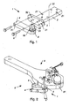
- FIG. 1 an exploded view of an embodiment of a positive steering module 1 according to the invention for trailer hitches 9 with a connecting element 2 and a guide member 5 is shown, wherein the connecting element 2 comprises a side member 3, a support member 4 is provided for receiving the guide member 5 and means for securing 31 of the support member 4 in at least two distinguishable positions are provided with the side member 3.
- the connecting element 2 comprises a side member 3
- a support member 4 is provided for receiving the guide member 5 and means for securing 31 of the support member 4 in at least two distinguishable positions are provided with the side member 3.
- the connecting element 2 is od for releasable attachment to a base plate 91.
- the trailer hitch 9 is provided.
- the connecting element 2 preferably - in the operating position of the trailer hitch 9 below the base plate 91 od.
- a simple releasable attachment can be achieved by means of screws.
- the guide rod a drawbar eye 7 according to the Fig. 7 to 24 include.
- At least a part of the wheels of the trailer can be adjusted depending on the pivoting angle of the trailer relative to a towing vehicle, whereby the driving behavior of the team can be improved in curves.
- the carrier element 4 is connectable to the side element 3 in a plurality of distinguishable positions, wherein at least two, preferably at least three distinguishable positions are provided.
- Fig. 1 is a first position
- Fig. 3 a second position
- Fig. 2 a drille position of the support element 4 is shown.
- the guide element 5 in the first position in a first direction
- the second position in a second direction, wherein the second direction is opposite to the first direction, and is rotated in the third position to the first position by a predetermined angle ⁇ arranged.
- angle ⁇ in the range of about 10 ° to about 30 °, in particular in the range of about 15 ° to 25 °.
- the pivotability of the trailer relative to the towing vehicle should be restricted as little as possible by the positive steering according to the invention.
- This can be achieved by arranging the forced steering module 1 and / or the guide linkage of the trailer connected to the forced steering module 1 outside the plane of the trailer coupling 9 and the trailer linkage connected therewith. This can be achieved in particular by the arrangement of the guide element 5 in the second or the third position.
- the number of required components can be kept particularly low if the support member 4 can be moved by turning from the first position to the second position and is connectable in both positions with the side member 3.
- the carrier element 4 has through-holes 41 and can be connected to the side element 3 by means of fastening means 6 received by the through-holes 41.
- the fastening means 6 may be in particular screws.
- the fastening means 6 are easily accessible, allowing a rapid movement of the support element 4 from one position to another position.
- connection with the carrier element 4 in distinguishable positions can be achieved by providing a plurality of threaded holes 32 in the side member 3.
- the guide element 5 can not be brought into the predetermined position for the articulation point, 3 further possible positions can be provided by attaching further threaded holes 32 in the side member 3, which can also be easily attached by an end user.
- the number of deployable articulation points can be further increased if the connecting element 2 comprises a fastening device 21, wherein the fastening device 21 is symmetrical with respect to a rotation of the connecting element 2 by substantially 180 °, wherein the side member 3 in rotation on an opposite side of the trailer hitch 9 is brought.
- the connecting element 2 about the axis 22 in Fig. 1 turned.
- the fastening device 21 is used for releasable attachment to the trailer hitch 9, the attachment - seen in the operating position of the trailer hitch 9 - can be done from below, whereby the function of the trailer hitch 9 is not affected. In a coupling device 8 can be ensured that the fastening means 6 and the fastening device 21 is particularly easy to access.
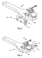
- Fig. 6 a further embodiment of the forced steering module 1 according to the invention is shown, in which two oppositely arranged side elements 3 are provided. With this embodiment, two articulation points can be provided simultaneously.
- the side member 3 may be detachably or permanently connected to the connecting element 2.
- An insoluble connection which in particular can be welded, appears particularly favorable.
- the outer surface of the side member 3 is not required for connection to the connecting element 2, whereby the number and arrangement of the threaded bores 32 on the side member 3 is not affected by the connection of the side member 3 with the connecting element 2.
- Fig. 1 to 6 shown articulation points can be provided with only three different components, each having a simple structure. As a result, manufacturing and storage costs can be kept low.
- the guide member 5 is formed as a coupling ball 51, then a forced steering can be achieved with only a small clearance, whereby the reliability and safety of the forced steering is increased.
- the guide element 5 may also be designed as hooks, bolts or the like.
- a particularly long service life of the guide element 5 can be achieved if the guide element 5 has at least one lubricating device 52, in particular a lubricating bore 53.
- the guide linkage of the trailer comprises a drawbar eye 7.
- a hold-down device can be fastened on the carrier element 4.
- the required height can be kept particularly low when a drawbar eye 7 according to the Fig. 7 to 24 is used.
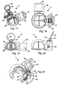
- the drawbar eye 7 has a ball inner surface 71, wherein the ball inner surface 71 has a recess 72 and an actuating element 73 can be brought into the recess 72. By the actuating element 73, a secure hold of the drawbar eye 7 can be ensured on the trained as a coupling ball 51 guide member 5. It can be exploited in particular that usually only small support loads are to be transmitted in a forced steering.
- the drawbar eye 7 has a drawbar shank 78.
- the drawbar eye 78 may be connected to a steering linkage of a trailer.
- the towing eye as in the FIGS. 12 to 24 is shown, has a substantially pin-shaped actuating member 73 which has a ball inner surface 71 corresponding engagement portion 74 into which recesses 72 can be brought and wherein the longitudinal axis of the actuating element 73 outside of the longitudinal axis of the Glasösenschaftes 78 and the center of the ball Inner surface 71 formed symmetry plane is located.
- the plane of symmetry forms - in the position of use of the drawbar eye 7 - usually a vertical plane, which in addition to the center of the ball inner surface 71 and the vertex of the ball inner surface 71 includes.
- the plane of symmetry is also a plane of symmetry of an ideal drawbar eye 7 without actuating element 73.
- the plane of symmetry can also be uniquely determined in one embodiment of a drawbar eye 7 be, in which the center of the ball inner surface 71 coincides with the longitudinal axis of the drawbar shank 78.
- the longitudinal axis of the actuating element 73 with the plane of symmetry forms an angle of at least 10 °, preferably of at least 45 °, in particular of substantially 90 °. It has been shown that an increased load capacity of the drawbar shank 78 can be achieved even at an angle of 10 °. At 90 °, a particularly good decoupling is given. At 45 °, in comparison to 90 °, a more compact design of the drawbar eye 7 is obtained.
- the actuating element 73 may be arranged on both sides of the plane of symmetry. In other embodiments, two actuators 73 may be provided, whereby an increased support load can be absorbed by the towing eye 7. The actuator 73 may be performed in an integrally formed on the towing eye 7 extension 79.
- the recess 72 is arranged outside the extension of the drawbar shank 78 to the center of the ball inner surface 71. As a result of this design, an influence on the voltage curve in the drawbar shaft 78 by the actuating element 73 is largely avoided.
- the recess 72 may be substantially wedge-shaped. Furthermore, the actuating element 73 may have an engagement region 74 corresponding to the ball inner surface 71. Furthermore, it appears advantageous if the entire ball inner surface 71, which is distinguishable from the recess 72, is designed as a bearing surface.
- the bearing surface provided by the ball inner surface 71 can be essentially hemispherical in this case.
- the engagement region 74 of the actuating element 73 is also engaged with the coupling ball 51 in the coupled state and forms a further bearing surface. Due to the design according to the ball inner surface 71, this additional support surface can be chosen to be particularly large, whereby the voltages occurring can be kept low.
- the ball inner surface 71 may have lubricating grooves 84, whereby a good lubrication and a safe sliding of the drawbar eye 7 on the coupling ball 51 can be ensured.
- the actuating element 73 can be brought out of engagement with the guide element 5.
- a tension element in particular a ring 81, a chain or the like, can be connected to the actuating element 73 by means of a transverse bore 75.
- a secure hold of the actuating element 73 in the coupled position can be achieved by the provision of an elastic element 83, in particular a spring or the like, whereby the elastic element 83 can be arranged in a storage space 76, for example.
- the ring 81 can be snapped onto a nose of the extension 79. This is in the embodiments according to the Fig. 12 to 16 and 22 to 24 the case.
- the actuating element 73 may also be secured by means of a pin 82 which is laterally insertable and fixable.
- the drawbar eye 7 has a receptacle 77 for the guide pole length.
- a particularly simple embodiment of the drawbar eye 7 can be achieved with a substantially cylindrical actuating element 73.
- a guide spring By forming a guide spring can be formed in a simple manner, a rotation of the actuating element 73. In other embodiments, an anti-rotation can be achieved for example by the choice of an elliptical and / or prismatic cross-section.
- the required construction volume for the forced steering can be kept particularly low.
Landscapes
- Engineering & Computer Science (AREA)
- Transportation (AREA)
- Mechanical Engineering (AREA)
- Steering-Linkage Mechanisms And Four-Wheel Steering (AREA)
- Pivots And Pivotal Connections (AREA)
- Air Bags (AREA)
- Orthopedics, Nursing, And Contraception (AREA)
- Quick-Acting Or Multi-Walled Pipe Joints (AREA)
- Medical Preparation Storing Or Oral Administration Devices (AREA)
- Power Steering Mechanism (AREA)
- Arrangement And Driving Of Transmission Devices (AREA)
- Prostheses (AREA)
Claims (10)
- Anneau de traction (7) pour une direction forcée comportant une boule d'attelage (51), avec un corps d'anneau de traction (78) et une surface intérieure sphérique (71), laquelle surface intérieure sphérique (71) présente un creux (72), caractérisé en ce qu'un élément d'actionnement (73) sensiblement en forme de goupille, qui présente une zone de prise (74) correspondant à la surface intérieure sphérique (71), peut être introduit dans le creux (72) et en ce que l'axe longitudinal de l'élément d'actionnement (73) se trouve en dehors du plan de symétrie formé par l'axe longitudinal du corps d'anneau de traction (78) et le centre de la surface intérieure sphérique (71).
- Anneau de traction (7) selon la revendication 1, caractérisé en ce que l'axe longitudinal de l'élément d'actionnement (73) forme avec le plan de symétrie un angle d'au moins 10°, de préférence d'au moins 45°, en particulier sensiblement de 90°.
- Anneau de traction (7) selon la revendication 1 ou 2, caractérisé en ce que le creux (72) est disposé en dehors du prolongement du corps d'anneau de traction (78) jusqu'au milieu de la surface intérieure sphérique (71).
- Anneau de traction (7) selon l'une des revendications 1 à 3, caractérisé en ce que l'ensemble de la surface intérieure sphérique (71) distincte du creux (72) est conformé comme une surface d'appui.
- Dispositif d'attelage (8) avec un anneau de traction (7) selon l'une des revendications 1 à 4.
- Dispositif d'attelage selon la revendication 5, caractérisé en ce que l'anneau de traction (7) coopère avec un module de direction forcée (1), en ce que le module de direction forcée (1) possède un élément de liaison (2) pour la fixation amovible à une plaque de base (91) ou à un attelage de remorque (9) et un élément de guidage (5) conformé comme une boule d'attelage (51) pour la liaison avec l'anneau de traction (7), en ce que l'élément de liaison (2) comprend au moins un élément latéral (3), en ce qu'il est prévu un élément de support (4) pour recevoir l'élément de guidage (5) et en ce que sont prévus des dispositifs pour la fixation (31) de l'élément de support (4) à l'élément latéral (3) dans au moins deux positions distinctes.
- Dispositif d'attelage selon la revendication 6, caractérisé en ce que la fixation de l'élément de support (4) est prévue dans au moins trois positions distinctes avec l'élément latéral (3).
- Dispositif d'attelage selon la revendication 6 ou 7, caractérisé en ce que l'élément de guidage (5) est orienté dans une première direction dans une première position, dans une deuxième direction opposée à la première direction dans une deuxième position et tourné selon un angle (α) pouvant être prédéterminé par rapport à la première position dans une troisième position.
- Dispositif d'attelage selon l'une des revendications 6 à 8, caractérisé en ce qu'il est prévu deux éléments latéraux (3) disposés l'un en face de l'autre.
- Dispositif d'attelage selon l'une des revendications 6 à 9, caractérisé en ce que l'élément latéral (3) est relié de manière inamovible à l'élément de liaison (2), en particulier soudé.
Priority Applications (1)
| Application Number | Priority Date | Filing Date | Title |
|---|---|---|---|
| PL07023820T PL1900552T3 (pl) | 2004-01-30 | 2005-01-28 | Ucho pociągowe dla kuli holowniczej |
Applications Claiming Priority (2)
| Application Number | Priority Date | Filing Date | Title |
|---|---|---|---|
| AT0012704A AT413026B (de) | 2004-01-30 | 2004-01-30 | Zwangslenkungsmodul |
| EP05450014A EP1559592B1 (fr) | 2004-01-30 | 2005-01-28 | Direction forcée pour attache de remorque |
Related Parent Applications (1)
| Application Number | Title | Priority Date | Filing Date |
|---|---|---|---|
| EP05450014A Division EP1559592B1 (fr) | 2004-01-30 | 2005-01-28 | Direction forcée pour attache de remorque |
Publications (3)
| Publication Number | Publication Date |
|---|---|
| EP1900552A2 EP1900552A2 (fr) | 2008-03-19 |
| EP1900552A3 EP1900552A3 (fr) | 2008-04-16 |
| EP1900552B1 true EP1900552B1 (fr) | 2009-04-29 |
Family
ID=34222833
Family Applications (2)
| Application Number | Title | Priority Date | Filing Date |
|---|---|---|---|
| EP05450014A Expired - Lifetime EP1559592B1 (fr) | 2004-01-30 | 2005-01-28 | Direction forcée pour attache de remorque |
| EP07023820A Expired - Lifetime EP1900552B1 (fr) | 2004-01-30 | 2005-01-28 | Anneau de remorquage pour une barre à rotule |
Family Applications Before (1)
| Application Number | Title | Priority Date | Filing Date |
|---|---|---|---|
| EP05450014A Expired - Lifetime EP1559592B1 (fr) | 2004-01-30 | 2005-01-28 | Direction forcée pour attache de remorque |
Country Status (5)
| Country | Link |
|---|---|
| US (1) | US20050208810A1 (fr) |
| EP (2) | EP1559592B1 (fr) |
| AT (3) | AT413026B (fr) |
| DE (2) | DE502005003403D1 (fr) |
| PL (1) | PL1900552T3 (fr) |
Families Citing this family (15)
| Publication number | Priority date | Publication date | Assignee | Title |
|---|---|---|---|---|
| DE202006004188U1 (de) * | 2006-03-14 | 2006-06-22 | Sauermann, Hans | Kupplungssystem für ein Zugfahrzeug und einen Anhänger |
| AT504906B1 (de) * | 2007-05-22 | 2008-09-15 | Christine Scharmueller | Niederhaltervorrichtung |
| AT506237B1 (de) * | 2007-12-21 | 2009-10-15 | Josef Ing Scharmueller | Zwangslenkungssystem |
| EP2230435A1 (fr) * | 2009-03-16 | 2010-09-22 | Caterpillar Work Tools B. V. | Coupleur fluide extensible |
| BRPI0924872B1 (pt) * | 2009-06-08 | 2020-02-04 | Josef Scharmueller | sistema de direção forçada e processo para acoplamento de um sistema de direção forçada |
| AT507665B1 (de) * | 2009-06-16 | 2010-07-15 | Scharmueller Josef Ing | Anhängerkupplung |
| AT508429B1 (de) * | 2009-07-03 | 2011-07-15 | Josef Ing Scharmueller | Zugöse |
| DE202010014352U1 (de) * | 2010-10-18 | 2011-03-17 | Agco Gmbh | Zugkugelkupplungsvorrichtung |
| US9250402B2 (en) * | 2013-02-05 | 2016-02-02 | Sumitomo Electric Industries, Ltd. | Pluggable optical transceiver having pull-pull-tab |
| EP3379222B1 (fr) | 2017-03-22 | 2020-12-30 | Methode Electronics Malta Ltd. | Ensemble de capteur à base magnétoélastique |
| US11135882B2 (en) | 2018-02-27 | 2021-10-05 | Methode Electronics, Inc. | Towing systems and methods using magnetic field sensing |
| US11221262B2 (en) | 2018-02-27 | 2022-01-11 | Methode Electronics, Inc. | Towing systems and methods using magnetic field sensing |
| US11084342B2 (en) | 2018-02-27 | 2021-08-10 | Methode Electronics, Inc. | Towing systems and methods using magnetic field sensing |
| EP3758959B1 (fr) | 2018-02-27 | 2025-11-05 | Methode Electronics, Inc. | Systèmes et procédés de remorquage utilisant la détection magnétique |
| US11491832B2 (en) | 2018-02-27 | 2022-11-08 | Methode Electronics, Inc. | Towing systems and methods using magnetic field sensing |
Family Cites Families (22)
| Publication number | Priority date | Publication date | Assignee | Title |
|---|---|---|---|---|
| GB857248A (en) * | 1957-10-24 | 1960-12-29 | Henry Edward Billington | Improvements relating to vehicle coupling and draw gear |
| US3436101A (en) * | 1967-05-04 | 1969-04-01 | Roy R Hanson | Lubricating hitch ball device |
| US3957286A (en) * | 1975-02-28 | 1976-05-18 | Valley Tow-Rite | Sway control adaptor |
| AU2351277A (en) * | 1976-04-22 | 1978-09-28 | Girlock Ltd | Coupling |
| US4306734A (en) * | 1979-06-29 | 1981-12-22 | Atwood Vacuum Machine Company | Apparatus for use with a trailer equipped with a surge brake actuator and with an anti-sway mechanism |
| GB2067486A (en) * | 1980-01-09 | 1981-07-30 | Fagg & Son Ltd W H J | Locking device |
| SU874392A1 (ru) * | 1980-02-20 | 1981-10-23 | Предприятие П/Я Р-6324 | Т гово-сцепное устройство |
| DE3030433A1 (de) * | 1980-08-12 | 1982-03-11 | Fritz Bauer + Söhne oHG, 8503 Altdorf | Winkelgelenk |
| AU571715B2 (en) * | 1984-07-24 | 1988-04-21 | Carter Wesco Sales Pty. Ltd. | Lockable tow ball trailer coupling |
| US4778196A (en) * | 1987-09-25 | 1988-10-18 | Spoliansky William S | Twist-latch trailer hitch |
| US4832360A (en) * | 1988-03-17 | 1989-05-23 | Christian Douglas R | Greaseball hitch |
| DE3912659C1 (fr) * | 1989-04-18 | 1990-10-31 | Ott Maschinentechnik Gmbh, 8960 Kempten, De | |
| ATE130919T1 (de) * | 1991-07-09 | 1995-12-15 | Faster Srl | Schnellkupplung zum jeweils gleichzeitigen herstellen oder lösen der verbindungen mehrerer kupplungen und/oder anschlussstecker, insbesondere kupplungsblock für anbaufrontlader an fahrzeugen. |
| SE467742B (sv) * | 1991-09-06 | 1992-09-07 | Sonerud John Teodor | Anordning foer snabbkoppling av ett redskap till en graevmaskin med samtidig anslutning till ett drivsystem |
| US5316033A (en) * | 1992-07-04 | 1994-05-31 | Gustav Schumacher | Coupling for connecting hydraulic lines |
| SE9600608L (sv) * | 1996-02-19 | 1997-02-17 | Kavlugnt Ab | Kopplingsanordning för sammankoppling av ett arbetsredskap till en arbetsmaskin; både mekanisk hopkoppling och snabbkoppling av hydraullikkopplingarna |
| US5829337A (en) * | 1997-08-28 | 1998-11-03 | Caterpillar Inc. | Method and apparatus for coupling a fluid-powered implement to a work machine |
| US6196265B1 (en) * | 1998-07-29 | 2001-03-06 | Wec Co. | Multi-line fluid connector |
| AU2250599A (en) * | 1999-03-30 | 2000-10-05 | Trapezium Developments Cc A South African Company | Tow hitch |
| US6283489B1 (en) * | 1999-09-27 | 2001-09-04 | Josef Thomas Hoog | Anti-sway control device for trailers |
| US6746036B2 (en) * | 2001-03-30 | 2004-06-08 | Cequent Towing Products, Inc. | Sway control conversion bracket |
| FR2828532B1 (fr) * | 2001-08-08 | 2003-11-07 | Hydro Techma | Remorque a train de roues orientable commande par les changements d'orientation d'un vehicule tracteur |
-
2004
- 2004-01-30 AT AT0012704A patent/AT413026B/de not_active IP Right Cessation
-
2005
- 2005-01-28 DE DE502005003403T patent/DE502005003403D1/de not_active Expired - Lifetime
- 2005-01-28 AT AT05450014T patent/ATE390303T1/de not_active IP Right Cessation
- 2005-01-28 PL PL07023820T patent/PL1900552T3/pl unknown
- 2005-01-28 DE DE502005007215T patent/DE502005007215D1/de not_active Expired - Lifetime
- 2005-01-28 EP EP05450014A patent/EP1559592B1/fr not_active Expired - Lifetime
- 2005-01-28 EP EP07023820A patent/EP1900552B1/fr not_active Expired - Lifetime
- 2005-01-28 AT AT07023820T patent/ATE430042T1/de not_active IP Right Cessation
- 2005-04-07 US US11/101,108 patent/US20050208810A1/en not_active Abandoned
Also Published As
| Publication number | Publication date |
|---|---|
| ATE390303T1 (de) | 2008-04-15 |
| EP1900552A3 (fr) | 2008-04-16 |
| AT413026B (de) | 2005-10-15 |
| DE502005003403D1 (de) | 2008-05-08 |
| ATA1272004A (de) | 2005-03-15 |
| DE502005007215D1 (de) | 2009-06-10 |
| EP1900552A2 (fr) | 2008-03-19 |
| EP1559592A1 (fr) | 2005-08-03 |
| EP1559592B1 (fr) | 2008-03-26 |
| ATE430042T1 (de) | 2009-05-15 |
| US20050208810A1 (en) | 2005-09-22 |
| PL1900552T3 (pl) | 2009-09-30 |
Similar Documents
| Publication | Publication Date | Title |
|---|---|---|
| EP1900552B1 (fr) | Anneau de remorquage pour une barre à rotule | |
| DE4118683C1 (fr) | ||
| DE3883981T2 (de) | Biegsamer arm. | |
| AT504906B1 (de) | Niederhaltervorrichtung | |
| DE102016104188B4 (de) | Vorrichtung zum Aktivieren von mindestens einer Funktionskomponente einer automatischen Mittelpufferkupplung | |
| DE1950336A1 (de) | Kupplung fuer Fahrzeuge von Modelleisenbahnen | |
| EP1433628B1 (fr) | Attelage de remorque de tracteur agricole | |
| DE3782142T2 (de) | Radlager, insbesondere fuer spielfahrzeuge. | |
| EP1682364B1 (fr) | Anneau de remorquage supportant des charges elevees | |
| EP1488942A1 (fr) | Attache remorque | |
| AT412712B (de) | Hubkupplung | |
| AT504478B1 (de) | Niederhalter | |
| EP1418067A2 (fr) | Anneau de remorquage | |
| DD244316A5 (de) | Verankerungssystem fuer starre achsen von fahrzeugen mit staarr an dem fahrgestell befestigten, vertikal beweglichen aufhaengungen | |
| DE60204084T2 (de) | Pflugscharanker | |
| DE102010043164B4 (de) | Kugelschwenkmodul für eine Anhängerkupplung | |
| EP1468848A1 (fr) | Attelage pour vehicule | |
| EP1767734A2 (fr) | Liaison articulée et charnière à articulations multiples avec une telle liaison articulée | |
| EP1867500A1 (fr) | Couplage de moyeux | |
| DE3540641A1 (de) | Anhaengerkupplung - stichwort: "kupplungsmaulzentrierung am automatikgehaeuse" | |
| EP1302341B1 (fr) | Attelage de remorque | |
| EP0603559B1 (fr) | Attelage de remorque amovible | |
| DE102004012483B4 (de) | Kupplungseinrichtung zum Verbinden eines Zugfahrzeuges mit einem Anhänger | |
| EP3832154B1 (fr) | Élément palier pour une rotule et ensemble à rotule avec un élément palier | |
| EP1582443B1 (fr) | Dispositif de basculement pour cabines suspendues disposé sur le châssis d'un camion |
Legal Events
| Date | Code | Title | Description |
|---|---|---|---|
| PUAI | Public reference made under article 153(3) epc to a published international application that has entered the european phase |
Free format text: ORIGINAL CODE: 0009012 |
|
| PUAL | Search report despatched |
Free format text: ORIGINAL CODE: 0009013 |
|
| AC | Divisional application: reference to earlier application |
Ref document number: 1559592 Country of ref document: EP Kind code of ref document: P |
|
| AK | Designated contracting states |
Kind code of ref document: A2 Designated state(s): AT BE BG CH CY CZ DE DK EE ES FI FR GB GR HU IE IS IT LI LT LU MC NL PL PT RO SE SI SK TR |
|
| RTI1 | Title (correction) |
Free format text: TOWING EYE FOR A BALL HITCH |
|
| AK | Designated contracting states |
Kind code of ref document: A3 Designated state(s): AT BE BG CH CY CZ DE DK EE ES FI FR GB GR HU IE IS IT LI LT LU MC NL PL PT RO SE SI SK TR |
|
| 17P | Request for examination filed |
Effective date: 20081016 |
|
| GRAP | Despatch of communication of intention to grant a patent |
Free format text: ORIGINAL CODE: EPIDOSNIGR1 |
|
| AKX | Designation fees paid |
Designated state(s): AT BE BG CH CY CZ DE DK EE ES FI FR GB GR HU IE IS IT LI LT LU MC NL PL PT RO SE SI SK TR |
|
| GRAS | Grant fee paid |
Free format text: ORIGINAL CODE: EPIDOSNIGR3 |
|
| GRAA | (expected) grant |
Free format text: ORIGINAL CODE: 0009210 |
|
| AC | Divisional application: reference to earlier application |
Ref document number: 1559592 Country of ref document: EP Kind code of ref document: P |
|
| AK | Designated contracting states |
Kind code of ref document: B1 Designated state(s): AT BE BG CH CY CZ DE DK EE ES FI FR GB GR HU IE IS IT LI LT LU MC NL PL PT RO SE SI SK TR |
|
| REG | Reference to a national code |
Ref country code: GB Ref legal event code: FG4D Free format text: NOT ENGLISH |
|
| REG | Reference to a national code |
Ref country code: CH Ref legal event code: EP |
|
| REF | Corresponds to: |
Ref document number: 502005007215 Country of ref document: DE Date of ref document: 20090610 Kind code of ref document: P |
|
| REG | Reference to a national code |
Ref country code: IE Ref legal event code: FG4D |
|
| REG | Reference to a national code |
Ref country code: PL Ref legal event code: T3 |
|
| NLV1 | Nl: lapsed or annulled due to failure to fulfill the requirements of art. 29p and 29m of the patents act | ||
| PG25 | Lapsed in a contracting state [announced via postgrant information from national office to epo] |
Ref country code: FI Free format text: LAPSE BECAUSE OF FAILURE TO SUBMIT A TRANSLATION OF THE DESCRIPTION OR TO PAY THE FEE WITHIN THE PRESCRIBED TIME-LIMIT Effective date: 20090429 Ref country code: LT Free format text: LAPSE BECAUSE OF FAILURE TO SUBMIT A TRANSLATION OF THE DESCRIPTION OR TO PAY THE FEE WITHIN THE PRESCRIBED TIME-LIMIT Effective date: 20090429 Ref country code: PT Free format text: LAPSE BECAUSE OF FAILURE TO SUBMIT A TRANSLATION OF THE DESCRIPTION OR TO PAY THE FEE WITHIN THE PRESCRIBED TIME-LIMIT Effective date: 20090829 Ref country code: ES Free format text: LAPSE BECAUSE OF FAILURE TO SUBMIT A TRANSLATION OF THE DESCRIPTION OR TO PAY THE FEE WITHIN THE PRESCRIBED TIME-LIMIT Effective date: 20090809 |
|
| PG25 | Lapsed in a contracting state [announced via postgrant information from national office to epo] |
Ref country code: IS Free format text: LAPSE BECAUSE OF FAILURE TO SUBMIT A TRANSLATION OF THE DESCRIPTION OR TO PAY THE FEE WITHIN THE PRESCRIBED TIME-LIMIT Effective date: 20090829 Ref country code: SI Free format text: LAPSE BECAUSE OF FAILURE TO SUBMIT A TRANSLATION OF THE DESCRIPTION OR TO PAY THE FEE WITHIN THE PRESCRIBED TIME-LIMIT Effective date: 20090429 Ref country code: NL Free format text: LAPSE BECAUSE OF FAILURE TO SUBMIT A TRANSLATION OF THE DESCRIPTION OR TO PAY THE FEE WITHIN THE PRESCRIBED TIME-LIMIT Effective date: 20090429 Ref country code: SE Free format text: LAPSE BECAUSE OF FAILURE TO SUBMIT A TRANSLATION OF THE DESCRIPTION OR TO PAY THE FEE WITHIN THE PRESCRIBED TIME-LIMIT Effective date: 20090729 |
|
| PG25 | Lapsed in a contracting state [announced via postgrant information from national office to epo] |
Ref country code: DK Free format text: LAPSE BECAUSE OF FAILURE TO SUBMIT A TRANSLATION OF THE DESCRIPTION OR TO PAY THE FEE WITHIN THE PRESCRIBED TIME-LIMIT Effective date: 20090429 Ref country code: EE Free format text: LAPSE BECAUSE OF FAILURE TO SUBMIT A TRANSLATION OF THE DESCRIPTION OR TO PAY THE FEE WITHIN THE PRESCRIBED TIME-LIMIT Effective date: 20090429 Ref country code: CZ Free format text: LAPSE BECAUSE OF FAILURE TO SUBMIT A TRANSLATION OF THE DESCRIPTION OR TO PAY THE FEE WITHIN THE PRESCRIBED TIME-LIMIT Effective date: 20090429 Ref country code: RO Free format text: LAPSE BECAUSE OF FAILURE TO SUBMIT A TRANSLATION OF THE DESCRIPTION OR TO PAY THE FEE WITHIN THE PRESCRIBED TIME-LIMIT Effective date: 20090429 |
|
| PG25 | Lapsed in a contracting state [announced via postgrant information from national office to epo] |
Ref country code: SK Free format text: LAPSE BECAUSE OF FAILURE TO SUBMIT A TRANSLATION OF THE DESCRIPTION OR TO PAY THE FEE WITHIN THE PRESCRIBED TIME-LIMIT Effective date: 20090429 |
|
| PLBE | No opposition filed within time limit |
Free format text: ORIGINAL CODE: 0009261 |
|
| STAA | Information on the status of an ep patent application or granted ep patent |
Free format text: STATUS: NO OPPOSITION FILED WITHIN TIME LIMIT |
|
| PG25 | Lapsed in a contracting state [announced via postgrant information from national office to epo] |
Ref country code: BG Free format text: LAPSE BECAUSE OF FAILURE TO SUBMIT A TRANSLATION OF THE DESCRIPTION OR TO PAY THE FEE WITHIN THE PRESCRIBED TIME-LIMIT Effective date: 20090729 |
|
| 26N | No opposition filed |
Effective date: 20100201 |
|
| BERE | Be: lapsed |
Owner name: SCHARMULLER, JOSEF Effective date: 20100131 |
|
| PG25 | Lapsed in a contracting state [announced via postgrant information from national office to epo] |
Ref country code: MC Free format text: LAPSE BECAUSE OF NON-PAYMENT OF DUE FEES Effective date: 20100131 |
|
| REG | Reference to a national code |
Ref country code: CH Ref legal event code: PL |
|
| PG25 | Lapsed in a contracting state [announced via postgrant information from national office to epo] |
Ref country code: LI Free format text: LAPSE BECAUSE OF NON-PAYMENT OF DUE FEES Effective date: 20100131 Ref country code: CH Free format text: LAPSE BECAUSE OF NON-PAYMENT OF DUE FEES Effective date: 20100131 Ref country code: GR Free format text: LAPSE BECAUSE OF FAILURE TO SUBMIT A TRANSLATION OF THE DESCRIPTION OR TO PAY THE FEE WITHIN THE PRESCRIBED TIME-LIMIT Effective date: 20090730 |
|
| PG25 | Lapsed in a contracting state [announced via postgrant information from national office to epo] |
Ref country code: BE Free format text: LAPSE BECAUSE OF NON-PAYMENT OF DUE FEES Effective date: 20100131 |
|
| PGFP | Annual fee paid to national office [announced via postgrant information from national office to epo] |
Ref country code: PL Payment date: 20101206 Year of fee payment: 7 |
|
| PG25 | Lapsed in a contracting state [announced via postgrant information from national office to epo] |
Ref country code: AT Free format text: LAPSE BECAUSE OF NON-PAYMENT OF DUE FEES Effective date: 20100128 |
|
| PGFP | Annual fee paid to national office [announced via postgrant information from national office to epo] |
Ref country code: TR Payment date: 20120126 Year of fee payment: 8 |
|
| PG25 | Lapsed in a contracting state [announced via postgrant information from national office to epo] |
Ref country code: CY Free format text: LAPSE BECAUSE OF FAILURE TO SUBMIT A TRANSLATION OF THE DESCRIPTION OR TO PAY THE FEE WITHIN THE PRESCRIBED TIME-LIMIT Effective date: 20090429 |
|
| PG25 | Lapsed in a contracting state [announced via postgrant information from national office to epo] |
Ref country code: LU Free format text: LAPSE BECAUSE OF NON-PAYMENT OF DUE FEES Effective date: 20100128 Ref country code: HU Free format text: LAPSE BECAUSE OF FAILURE TO SUBMIT A TRANSLATION OF THE DESCRIPTION OR TO PAY THE FEE WITHIN THE PRESCRIBED TIME-LIMIT Effective date: 20091030 |
|
| PGFP | Annual fee paid to national office [announced via postgrant information from national office to epo] |
Ref country code: IE Payment date: 20140121 Year of fee payment: 10 |
|
| REG | Reference to a national code |
Ref country code: PL Ref legal event code: LAPE |
|
| PG25 | Lapsed in a contracting state [announced via postgrant information from national office to epo] |
Ref country code: PL Free format text: LAPSE BECAUSE OF NON-PAYMENT OF DUE FEES Effective date: 20130128 |
|
| PGFP | Annual fee paid to national office [announced via postgrant information from national office to epo] |
Ref country code: FR Payment date: 20140124 Year of fee payment: 10 Ref country code: IT Payment date: 20140130 Year of fee payment: 10 |
|
| PGFP | Annual fee paid to national office [announced via postgrant information from national office to epo] |
Ref country code: GB Payment date: 20140123 Year of fee payment: 10 |
|
| GBPC | Gb: european patent ceased through non-payment of renewal fee |
Effective date: 20150128 |
|
| PG25 | Lapsed in a contracting state [announced via postgrant information from national office to epo] |
Ref country code: GB Free format text: LAPSE BECAUSE OF NON-PAYMENT OF DUE FEES Effective date: 20150128 |
|
| REG | Reference to a national code |
Ref country code: FR Ref legal event code: ST Effective date: 20150930 |
|
| REG | Reference to a national code |
Ref country code: IE Ref legal event code: MM4A |
|
| PG25 | Lapsed in a contracting state [announced via postgrant information from national office to epo] |
Ref country code: FR Free format text: LAPSE BECAUSE OF NON-PAYMENT OF DUE FEES Effective date: 20150202 |
|
| PG25 | Lapsed in a contracting state [announced via postgrant information from national office to epo] |
Ref country code: IT Free format text: LAPSE BECAUSE OF NON-PAYMENT OF DUE FEES Effective date: 20150128 |
|
| PG25 | Lapsed in a contracting state [announced via postgrant information from national office to epo] |
Ref country code: IE Free format text: LAPSE BECAUSE OF NON-PAYMENT OF DUE FEES Effective date: 20150128 |
|
| PGFP | Annual fee paid to national office [announced via postgrant information from national office to epo] |
Ref country code: DE Payment date: 20170125 Year of fee payment: 13 |
|
| PG25 | Lapsed in a contracting state [announced via postgrant information from national office to epo] |
Ref country code: TR Free format text: LAPSE BECAUSE OF NON-PAYMENT OF DUE FEES Effective date: 20140128 |
|
| REG | Reference to a national code |
Ref country code: DE Ref legal event code: R119 Ref document number: 502005007215 Country of ref document: DE |
|
| PG25 | Lapsed in a contracting state [announced via postgrant information from national office to epo] |
Ref country code: DE Free format text: LAPSE BECAUSE OF NON-PAYMENT OF DUE FEES Effective date: 20180801 |