EP1418067A2 - Anneau de remorquage - Google Patents
Anneau de remorquage Download PDFInfo
- Publication number
- EP1418067A2 EP1418067A2 EP03450231A EP03450231A EP1418067A2 EP 1418067 A2 EP1418067 A2 EP 1418067A2 EP 03450231 A EP03450231 A EP 03450231A EP 03450231 A EP03450231 A EP 03450231A EP 1418067 A2 EP1418067 A2 EP 1418067A2
- Authority
- EP
- European Patent Office
- Prior art keywords
- towing eye
- eye according
- flange
- fastening openings
- towing
- Prior art date
- Legal status (The legal status is an assumption and is not a legal conclusion. Google has not performed a legal analysis and makes no representation as to the accuracy of the status listed.)
- Granted
Links
Images


Classifications
-
- B—PERFORMING OPERATIONS; TRANSPORTING
- B60—VEHICLES IN GENERAL
- B60D—VEHICLE CONNECTIONS
- B60D1/00—Traction couplings; Hitches; Draw-gear; Towing devices
- B60D1/48—Traction couplings; Hitches; Draw-gear; Towing devices characterised by the mounting
- B60D1/56—Traction couplings; Hitches; Draw-gear; Towing devices characterised by the mounting securing to the vehicle bumper
- B60D1/565—Traction couplings; Hitches; Draw-gear; Towing devices characterised by the mounting securing to the vehicle bumper having an eyelet
-
- B—PERFORMING OPERATIONS; TRANSPORTING
- B60—VEHICLES IN GENERAL
- B60D—VEHICLE CONNECTIONS
- B60D1/00—Traction couplings; Hitches; Draw-gear; Towing devices
- B60D1/14—Draw-gear or towing devices characterised by their type
- B60D1/143—Draw-gear or towing devices characterised by their type characterised by the mounting of the draw-gear on the towed vehicle
-
- B—PERFORMING OPERATIONS; TRANSPORTING
- B60—VEHICLES IN GENERAL
- B60D—VEHICLE CONNECTIONS
- B60D1/00—Traction couplings; Hitches; Draw-gear; Towing devices
- B60D1/48—Traction couplings; Hitches; Draw-gear; Towing devices characterised by the mounting
- B60D1/54—Traction couplings; Hitches; Draw-gear; Towing devices characterised by the mounting collapsible or retractable when not in use, e.g. hide-away hitches
- B60D2001/542—Traction couplings; Hitches; Draw-gear; Towing devices characterised by the mounting collapsible or retractable when not in use, e.g. hide-away hitches characterised by the number of pivot axis
- B60D2001/544—Traction couplings; Hitches; Draw-gear; Towing devices characterised by the mounting collapsible or retractable when not in use, e.g. hide-away hitches characterised by the number of pivot axis one pivot axis
Definitions
- the invention relates to a towing eye of a clutch with a, in particular a ring, a Ball socket or the like.
- Towing eyes of this type are used, in particular, in couplings for motor vehicles, in particular agricultural machines, buses, trucks or the like. Used and serve in particular the Transmission of longitudinal forces, shear forces and bending moments between a trailer and a towing vehicle and / or another trailer.
- drawbar eyes have a flange with at least six Fastening openings, being seen in the position of use in the middle of the upper side, in a fastening opening in the middle of the lower side and in the corner areas is arranged.
- the mounting holes are for receiving mounting screws provided to attach the drawbar eye to a support plate or the like.
- the - right and left side of the flange each an additional mounting hole in the middle intended.
- a disadvantage of these known drawbar eyes is that the additional side Fastening openings and the additional fastening screws only increase the longitudinal forces that can be transmitted by the fastening screws, but not those that can be transmitted Bending moment is reached.
- Another disadvantage of these towing eyes is that they fail often occurs in the area of the spacer adjacent to the flange.
- the object of the invention is to provide a towing eye of the type mentioned, in which the known disadvantages are avoided, which has a high resilience overall and which can be connected to a support plate or the like, the connection being particularly high Can absorb longitudinal forces and bending moments.
- Another object of the invention is to provide a towing eye of the type mentioned specify which is simple and inexpensive to manufacture, which has a long service life and Security and a low probability of failure.
- the fastening openings can be found in the corner areas and screw supports are formed outside the transition area, with larger ones Fastening screws can be provided as in the side center areas could be ordered. Instead of a large fastening screw, the Corner areas also several smaller screws can be provided.
- Another advantage of Invention is that the surface of the corner areas around the mounting holes a lathe in one operation with the formation of screw supports can be turned off, making the towing eye according to the invention simple and inexpensive can be produced. Screw supports around fastening openings in the side center areas can be at least partially manufactured by means of a milling cutter or the like, since the Screw support partially in the transition area between the spacer and the flange is arranged.
- Another advantage of the invention is that the cross section of the Support element can be made stronger in the area adjacent to the flange and can optionally be additionally reinforced with ribs or the like.
- the invention is that the flange in the central region of the spacer opposite side is almost free of tension, which makes an open edge Recess for a holding element in the formation of a compared to the spacer rotatable coupling element can be provided.
- Another advantage is that in the Lateral center areas lines for lubricants or the like are arranged adjacent to the flange can be and do not need to be led around or over the mounting screws, which reduces the risk of damage to the lines and thereby the Improved safety of the towing eye according to the invention and their probability of failure is reduced.
- the side center areas overlap extend at least 20% of the longitudinal extent of the sides of the flange.
- each of the corner regions is arranged at least one fastening opening, whereby a even distribution of the forces on the arranged in the mounting holes Fixing screws can be reached.
- - in Seen position of use - at least in a substantially vertical row at least four mounting holes are provided.
- the Mounting holes in a substantially vertical row can be ensured that the towing eye according to the invention in various positions on a support plate or the like. can be fastened, which need only have a small number of bores. Thereby a high strength of the support plate or the like can be achieved.
- the distance between the adjacent mounting holes different corner areas an integer multiple, especially double, of Distance between the adjacent mounting holes within one of the Corner areas.
- This allows a height adjustment of the Towing eye according to the invention can be provided by additional or the like in the support plate Drilled holes in the grid size specified by the mounting holes become.
- the spacer element is a Has rounded transition area, which is connected to the flange is. Due to the rounded transition area, voltage peaks can occur in the transition be largely avoided between the flange and the spacer.
- the radius of the Rounding equal to or greater than the diameter of at least one of the Mounting holes is.
- the coupling element Rotating element comprises, which - in a manner known per se - in the spacer element an axis of rotation rotatably supported and by means of a holding element, in particular one Welding ring od.
- a holding element in particular one Welding ring od.
- the flange an open edge receiving opening for receiving at least part of the Has holding element.
- the overall length of the towing eye according to the invention can be reduced. Unless the holding element the flange protrudes, it is not necessary in the support plate, an opening for the holding element provide, which can improve the stability and resilience of the clutch.
- the holding element has at least one recess and / or at least one elevation, which with the at least one pressure element forms an anti-rotation device.
- a twist of the Coupling element opposite the spacer element is not provided in normal operation and is used in particular to ensure that a falling element does not collapse in an accident Overturning of another element coupled with this conditionally.
- the coupling element is opposite the Can only rotate the spacer element when a predeterminable torque is exceeded, wherein the formation of at least one recess and / or at least one elevation represents a simple and inexpensive to manufacture version of an anti-rotation device.
- Another possible embodiment of the invention may consist in that the Protection against rotation by an in the at least one recess of the holding element engaging rolling elements acted upon by the at least one pressure element, in particular a ball, a cylinder or the like.
- the rolling element engages Normal position of the towing eye in the recess, whereby when a Predeterminable torque is led out of the recess and between the Pressure body and the holding element is guided. When turning back the Coupling element, the rolling element snaps back into the recess.
- the Spacer and the flange are integrally formed. Through the one-piece Training can be a largely undisturbed flow of force between the spacer and the flange can be reached.
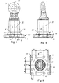
- 5 and 6 is an embodiment of a towing eye according to the invention
- Coupling with a coupling element 3, a spacer 2 and a one in essential square base flange 1 with corner regions 11 and arranged between the corner regions 11 along the sides 13 of the flange 1 Side center regions 12, with fastening openings 4 in the corner regions 11 are provided.
- the flange 1 can instead of a substantially square Base also have a substantially rectangular base, the corners rounded and / or the sides can also be curved.
- the coupling element 3 may comprise a ring 31 which is connected to a pin with a coupling device can be coupled. Instead of the ring 31, a ball socket or the like can also be provided, which can be coupled with a ball or the like.
- the coupling device, the Side center regions 12 are formed free of fastening openings 4.
- Towing eyes of this type are used, in particular, in couplings for motor vehicles, in particular agricultural machines, buses, trucks or the like. Used and serve in particular the Transmission of longitudinal forces and mainly from the vertical load component Shear forces and bending moments between a trailer and a towing vehicle and / or another trailer.
- the mounting holes 4 are od for receiving mounting screws or the like. provided by means of which the towing eye according to the invention is attached to a support plate or the like can be. By providing appropriate holes in the support plate or the like the towing eye can be attached at different positions. This is done by the arrangement of the fastening openings 4 is only high in the corner regions 11 Stability of the support plate or the like. Also with holes for fastening the towing eye reached different positions.
- the spacer 2 can be with the flange 1 by means of a rounding Transition area 21 may be connected, as a result of which the stresses in the transition area 21 can be kept low.
- Side center region 12 can be ensured that none of the fastening openings 4th and also no screw supports arranged around the fastening openings 4 Rounding of the transition area 21 cuts, resulting in the notch effect caused voltage peaks can be avoided. This allows the Resilience of the towing eye according to the invention can be improved.
- a particularly stable connection between the spacer element 2 and the flange 1 can be achieved if the spacer 2 and the flange 1 are integrally formed are.
- the radius r of the fillet is equal to or larger than that Diameter d is at least one of the fastening openings 4.
- the side center regions 12 extend over at least 20% of the longitudinal extent of the Pages 13 of the flange 1, so the transition region 21 and Fastening openings 4 and possibly the screw supports in a simple manner be spatially separated from each other, thereby making all Screw supports on a lathe in one step is made possible. Furthermore, can 12 lines for lubricants or the like Towing eye according to the invention are guided adjacent, whereby the risk of Damage to these lines is reduced and the safety of the towing eye is improved.
- At least one rib 22 or the like can be attached to the Spacer 2 may be formed, which with the flange 1 and one of the Side center areas 12 is connected.
- the lines for lubricants or the like can also be guided and / or formed within the rib 22 or the like.
- a flange 1 is shown schematically, the boundary between the Side center regions 12 and the corner regions 11 indicated by dashed lines are.
- Two or more fastening bores 11 can also be provided in the corner regions 11 be provided, wherein - seen in the position of use - in at least one essentially horizontal row 41 at least four mounting openings 4 can be provided.
- FIG. 7 to 11 is a further embodiment of a towing eye according to the invention in which there are three fastening devices 4 in each of the corner regions 11 are provided; whereby - seen in the position of use - two essentially horizontal Rows 41 and two substantially vertical rows 42 each four of the Fastening openings 4 are arranged. With this arrangement, the transition area 21 are particularly large. Furthermore, the large towing eye according to the invention the diameter of the fastening screws in one commercially available area.
- the distance b In at least one of the rows 41, 42 between the adjacent fastening openings 4 of different corner regions 11 integer multiple, especially double, of the distance a between the adjacent fastening openings 4 within one of the corner regions 11. It can thereby be achieved that in a support plate or the like. Which bores in one Has grid dimension with the distance a, the towing eye according to the invention at different Positions can be attached.
- the embodiment of a towing eye according to the invention shown in FIG. 15 has in each of the corner regions 11 have fastening openings 4, with 42 in each case four fastening openings 4 are arranged.
- This embodiment can on a Support plate or the like, which has two rows of holes offset in a simple manner become. This ensures a high strength of the support plate.
- the coupling element 3 can rotate with the spacer element, in particular in one piece, be connected.
- the coupling element 3 comprises a rotary element 32 which in the spacer element 2 by one Axis of rotation 33 is rotatably mounted and by means of a holding element 5 in the longitudinal direction Axis of rotation 33 is secured.
- the holding element 5 can be designed as a welding ring with which Screwed rotating element, shrunk onto it or the like.
- a short design of the Towing eye according to the invention can be achieved if the flange 1 is an open edge Has recess 14 for receiving at least part of the holding element 5.
- In 12 to 14 is another embodiment of a towing eye according to the invention shown, in which a part of the receiving opening 14 is shown enlarged.
- the holding element 5 does not protrude from the flange 1, it is not necessary in the Support plate to provide an opening for the holding element 5, whereby the stability and Resilience of the clutch can be improved.
- a rotation of the coupling element 3 with respect to the spacer element 2 is in the Normal operation is not provided and is used in particular in the event of an accident overturning element does not overturn another element coupled with it conditionally.
- a displacement of the coupling element 3 with respect to the spacer element 2 can largely prevent at least between the holding element 5 and the flange 1 a prestressable pressure element 6 acting in the longitudinal direction of the axis of rotation 33 is arranged his. This can ensure that the connection between the Spacer 2 and the coupling element 3 in the longitudinal direction of the axis of rotation 33 in is essentially free of play, which creates the risk of undesirable vibrations and Impacts reduced and the safety and life of the towing eye according to the invention is increased.
- the holding element 5 has at least one recess 51 and / or at least one elevation, which with the at least one Pressure element 6 forms an anti-rotation device, whereby a rotation of the Coupling element 3 with respect to the spacer element 2 only when a predeterminable torque is made possible.
- the recess 51 can be used as a depression, in particular as a groove or the like.
- the anti-rotation device is inserted into the at least one recess 51 of the Holding element 5 engaging the at least one pressure element 6 acted upon Rolling element 61, in particular a ball, a cylinder or the like, is formed, a Protection against rotation is provided, which after rotating the coupling element 3 opposite the spacer element 2 and a subsequent turning back of the coupling element 3 is functional again and can still be used.
- the rolling element 51 engages Normal position of the towing eye in the recess, whereby when the Predeterminable torque out of the recess 51 and between the Pressure body 6 and the holding element 5 is guided. When turning back the Coupling element 3 in a defined position, the rolling element 51 snaps back into the recess 5 on.
Landscapes
- Engineering & Computer Science (AREA)
- Transportation (AREA)
- Mechanical Engineering (AREA)
- Pivots And Pivotal Connections (AREA)
- Body Structure For Vehicles (AREA)
- Retarders (AREA)
- Dental Prosthetics (AREA)
Applications Claiming Priority (2)
| Application Number | Priority Date | Filing Date | Title |
|---|---|---|---|
| AT16962002 | 2002-11-11 | ||
| AT0169602A AT412268B (de) | 2002-11-11 | 2002-11-11 | Zugöse |
Publications (3)
| Publication Number | Publication Date |
|---|---|
| EP1418067A2 true EP1418067A2 (fr) | 2004-05-12 |
| EP1418067A3 EP1418067A3 (fr) | 2004-08-11 |
| EP1418067B1 EP1418067B1 (fr) | 2010-06-02 |
Family
ID=32097265
Family Applications (1)
| Application Number | Title | Priority Date | Filing Date |
|---|---|---|---|
| EP03450231A Expired - Lifetime EP1418067B1 (fr) | 2002-11-11 | 2003-10-15 | Anneau de remorquage |
Country Status (3)
| Country | Link |
|---|---|
| EP (1) | EP1418067B1 (fr) |
| AT (2) | AT412268B (fr) |
| DE (1) | DE50312758D1 (fr) |
Cited By (3)
| Publication number | Priority date | Publication date | Assignee | Title |
|---|---|---|---|---|
| EP2080644A1 (fr) * | 2008-01-18 | 2009-07-22 | Redrock Engineering limited | Crochet pivotant |
| CN106394143A (zh) * | 2016-09-21 | 2017-02-15 | 北京汽车股份有限公司 | 用于拖车钩装置的螺纹套筒组件和具有它的车辆 |
| WO2018036851A1 (fr) * | 2016-08-24 | 2018-03-01 | Josef Scharmüller | Système d'attelage |
Families Citing this family (4)
| Publication number | Priority date | Publication date | Assignee | Title |
|---|---|---|---|---|
| DE102020121793A1 (de) | 2020-08-19 | 2022-02-24 | Rühlicke GmbH | Anhängekupplung für Fahrzeuge |
| DE102021109066A1 (de) | 2021-04-12 | 2022-10-27 | Rühlicke GmbH | Kupplungsvorrichtung für ein in Zugrichtung hinteres Fahrzeug eines Fahrzeugverbundes |
| DE102021109065B3 (de) | 2021-04-12 | 2022-08-04 | Rühlicke GmbH | Kupplungsbolzen für ein Zugfahrzeug eines Fahrzeugverbundes |
| DE102022123103A1 (de) | 2022-09-12 | 2024-03-14 | Rühlicke GmbH | Kupplungsvorrichtung für ein in Zugrichtung hinteres Fahrzeug eines Fahrzeugverbundes |
Citations (7)
| Publication number | Priority date | Publication date | Assignee | Title |
|---|---|---|---|---|
| US2356998A (en) * | 1942-03-27 | 1944-08-29 | Haniquet George | Towing attachment |
| DE6910130U (de) * | 1969-03-10 | 1969-10-16 | Fendt & Co Xaver | Anhaengerkupplung |
| US4157189A (en) * | 1977-09-28 | 1979-06-05 | Poley Roger G | Trailer hitch bracket |
| DE3049456A1 (de) * | 1980-12-30 | 1982-07-29 | Paul 7936 Allmendingen Friese | Befestigungs-elemente |
| EP0650857A1 (fr) * | 1993-10-29 | 1995-05-03 | C.B.M. S.p.A. | Attelage pour véhicules, en particulier pour tracteurs agricoles et autres |
| US5725229A (en) * | 1996-08-29 | 1998-03-10 | Mcwethy; Wesley I. | Tow hitch apparatus |
| US20010038191A1 (en) * | 2000-04-10 | 2001-11-08 | Massey Randy A. | Vertically adjustable trailer hitch |
Family Cites Families (3)
| Publication number | Priority date | Publication date | Assignee | Title |
|---|---|---|---|---|
| DE3827842C2 (de) * | 1988-08-17 | 1996-04-11 | Bpw Fahrzeugtechnik Gmbh & Co | Längenveränderbare Zugdeichsel |
| FR2682324B1 (fr) * | 1991-10-14 | 1997-08-22 | Pommier & Cie | Anneau d'accouplement pour timon ou fleche de remorque. |
| EP1236590A1 (fr) * | 2001-03-02 | 2002-09-04 | Cramer Kupplung GmbH & Co. KG | Attelage de remorque |
-
2002
- 2002-11-11 AT AT0169602A patent/AT412268B/de not_active IP Right Cessation
-
2003
- 2003-10-15 AT AT03450231T patent/ATE469773T1/de not_active IP Right Cessation
- 2003-10-15 EP EP03450231A patent/EP1418067B1/fr not_active Expired - Lifetime
- 2003-10-15 DE DE50312758T patent/DE50312758D1/de not_active Expired - Lifetime
Patent Citations (7)
| Publication number | Priority date | Publication date | Assignee | Title |
|---|---|---|---|---|
| US2356998A (en) * | 1942-03-27 | 1944-08-29 | Haniquet George | Towing attachment |
| DE6910130U (de) * | 1969-03-10 | 1969-10-16 | Fendt & Co Xaver | Anhaengerkupplung |
| US4157189A (en) * | 1977-09-28 | 1979-06-05 | Poley Roger G | Trailer hitch bracket |
| DE3049456A1 (de) * | 1980-12-30 | 1982-07-29 | Paul 7936 Allmendingen Friese | Befestigungs-elemente |
| EP0650857A1 (fr) * | 1993-10-29 | 1995-05-03 | C.B.M. S.p.A. | Attelage pour véhicules, en particulier pour tracteurs agricoles et autres |
| US5725229A (en) * | 1996-08-29 | 1998-03-10 | Mcwethy; Wesley I. | Tow hitch apparatus |
| US20010038191A1 (en) * | 2000-04-10 | 2001-11-08 | Massey Randy A. | Vertically adjustable trailer hitch |
Non-Patent Citations (1)
| Title |
|---|
| XP002273890 Gefunden im Internet: URL:www.buyersproducts.com> [gefunden am 2004-03-17] * |
Cited By (4)
| Publication number | Priority date | Publication date | Assignee | Title |
|---|---|---|---|---|
| EP2080644A1 (fr) * | 2008-01-18 | 2009-07-22 | Redrock Engineering limited | Crochet pivotant |
| WO2018036851A1 (fr) * | 2016-08-24 | 2018-03-01 | Josef Scharmüller | Système d'attelage |
| CN106394143A (zh) * | 2016-09-21 | 2017-02-15 | 北京汽车股份有限公司 | 用于拖车钩装置的螺纹套筒组件和具有它的车辆 |
| CN106394143B (zh) * | 2016-09-21 | 2019-02-01 | 北京汽车股份有限公司 | 用于拖车钩装置的螺纹套筒组件和具有它的车辆 |
Also Published As
| Publication number | Publication date |
|---|---|
| ATA16962002A (de) | 2004-05-15 |
| DE50312758D1 (de) | 2010-07-15 |
| ATE469773T1 (de) | 2010-06-15 |
| AT412268B (de) | 2004-12-27 |
| EP1418067A3 (fr) | 2004-08-11 |
| EP1418067B1 (fr) | 2010-06-02 |
Similar Documents
| Publication | Publication Date | Title |
|---|---|---|
| EP2822888B1 (fr) | Vis à il | |
| EP1559592B1 (fr) | Direction forcée pour attache de remorque | |
| DE69912867T2 (de) | Befestigungsvorrichtung für einen Triebwerkträger eines Flugzeuges | |
| DE19929966A1 (de) | Sicherungssystem für einen Bolzen und eine Mutter | |
| EP1829716B1 (fr) | Attelage pour véhicules automobiles | |
| EP1248914B1 (fr) | Dispositif de fixation pour des pedales dans des vehicules automobiles | |
| EP1716065B1 (fr) | Bloc galet de roulement | |
| WO2012097810A2 (fr) | Dispositif d'application de force | |
| EP0913139B1 (fr) | Système de table d'opération modulaire | |
| EP1418067A2 (fr) | Anneau de remorquage | |
| EP1178232B1 (fr) | Elément entraineur à bride pour joint de cardan et arbre articulé | |
| DE102006056004B4 (de) | Gelenkbeschlag für Kraftfahrzeugsitze mit mindestens zwei Sperrarmen | |
| EP2130993B1 (fr) | Dispositif d'appui, notamment chandelle | |
| DE102016113897B4 (de) | Schwerlastschäkel | |
| EP0423474B1 (fr) | Dispositif pour relier deux baguettes profilées de façon à ce qu'elles soient détachables | |
| DE102007021747A1 (de) | Befestigungseinrichtung zur Ausbildung einer Schnittstelle von einem Rohbau zu einem Innenausbau bei einem Schienenfahrzeug | |
| DE112004001173B4 (de) | Gelenkbeschlag für Kraftfahrzeugsitze mit mindestens zwei Sperrarmen | |
| DE10212671B4 (de) | Kegelradausgleichsgetriebe | |
| EP3354907B1 (fr) | Ensemble de bagues d'arrêt | |
| AT6996U1 (de) | Zugöse | |
| WO2021047921A2 (fr) | Unité de rotation conçue pour un siège de véhicule pouvant tourner autour de son axe vertical, crochet de transmission de forces en cas de collision conçu pour une telle unité de rotation, et siège de véhicule rotatif | |
| DE102007021059A1 (de) | Flexibles Gelenk | |
| EP1683980B1 (fr) | Elément entraineur à bride pour joint de cardan et arbre articulé | |
| EP1355073B1 (fr) | Fourchette d'articulation et joint universal avec la même | |
| EP1117941A1 (fr) | Vis et tournevis permettant un accouplement vis/tournevis sans derapage |
Legal Events
| Date | Code | Title | Description |
|---|---|---|---|
| PUAI | Public reference made under article 153(3) epc to a published international application that has entered the european phase |
Free format text: ORIGINAL CODE: 0009012 |
|
| AK | Designated contracting states |
Kind code of ref document: A2 Designated state(s): AT BE BG CH CY CZ DE DK EE ES FI FR GB GR HU IE IT LI LU MC NL PT RO SE SI SK TR |
|
| AX | Request for extension of the european patent |
Extension state: AL LT LV MK |
|
| PUAL | Search report despatched |
Free format text: ORIGINAL CODE: 0009013 |
|
| AK | Designated contracting states |
Kind code of ref document: A3 Designated state(s): AT BE BG CH CY CZ DE DK EE ES FI FR GB GR HU IE IT LI LU MC NL PT RO SE SI SK TR |
|
| AX | Request for extension of the european patent |
Extension state: AL LT LV MK |
|
| 17P | Request for examination filed |
Effective date: 20050211 |
|
| AKX | Designation fees paid |
Designated state(s): AT BE BG CH CY CZ DE DK EE ES FI FR GB GR HU IE IT LI LU MC NL PT RO SE SI SK TR |
|
| 17Q | First examination report despatched |
Effective date: 20070523 |
|
| GRAP | Despatch of communication of intention to grant a patent |
Free format text: ORIGINAL CODE: EPIDOSNIGR1 |
|
| GRAS | Grant fee paid |
Free format text: ORIGINAL CODE: EPIDOSNIGR3 |
|
| GRAA | (expected) grant |
Free format text: ORIGINAL CODE: 0009210 |
|
| AK | Designated contracting states |
Kind code of ref document: B1 Designated state(s): AT BE BG CH CY CZ DE DK EE ES FI FR GB GR HU IE IT LI LU MC NL PT RO SE SI SK TR |
|
| REG | Reference to a national code |
Ref country code: GB Ref legal event code: FG4D Free format text: NOT ENGLISH |
|
| REG | Reference to a national code |
Ref country code: CH Ref legal event code: EP |
|
| REG | Reference to a national code |
Ref country code: IE Ref legal event code: FG4D Free format text: LANGUAGE OF EP DOCUMENT: GERMAN |
|
| REF | Corresponds to: |
Ref document number: 50312758 Country of ref document: DE Date of ref document: 20100715 Kind code of ref document: P |
|
| REG | Reference to a national code |
Ref country code: NL Ref legal event code: T3 |
|
| PG25 | Lapsed in a contracting state [announced via postgrant information from national office to epo] |
Ref country code: SE Free format text: LAPSE BECAUSE OF FAILURE TO SUBMIT A TRANSLATION OF THE DESCRIPTION OR TO PAY THE FEE WITHIN THE PRESCRIBED TIME-LIMIT Effective date: 20100602 |
|
| PG25 | Lapsed in a contracting state [announced via postgrant information from national office to epo] |
Ref country code: SI Free format text: LAPSE BECAUSE OF FAILURE TO SUBMIT A TRANSLATION OF THE DESCRIPTION OR TO PAY THE FEE WITHIN THE PRESCRIBED TIME-LIMIT Effective date: 20100602 Ref country code: FI Free format text: LAPSE BECAUSE OF FAILURE TO SUBMIT A TRANSLATION OF THE DESCRIPTION OR TO PAY THE FEE WITHIN THE PRESCRIBED TIME-LIMIT Effective date: 20100602 |
|
| PG25 | Lapsed in a contracting state [announced via postgrant information from national office to epo] |
Ref country code: CY Free format text: LAPSE BECAUSE OF FAILURE TO SUBMIT A TRANSLATION OF THE DESCRIPTION OR TO PAY THE FEE WITHIN THE PRESCRIBED TIME-LIMIT Effective date: 20100602 Ref country code: GR Free format text: LAPSE BECAUSE OF FAILURE TO SUBMIT A TRANSLATION OF THE DESCRIPTION OR TO PAY THE FEE WITHIN THE PRESCRIBED TIME-LIMIT Effective date: 20100903 |
|
| REG | Reference to a national code |
Ref country code: IE Ref legal event code: FD4D |
|
| PG25 | Lapsed in a contracting state [announced via postgrant information from national office to epo] |
Ref country code: IE Free format text: LAPSE BECAUSE OF FAILURE TO SUBMIT A TRANSLATION OF THE DESCRIPTION OR TO PAY THE FEE WITHIN THE PRESCRIBED TIME-LIMIT Effective date: 20100602 Ref country code: EE Free format text: LAPSE BECAUSE OF FAILURE TO SUBMIT A TRANSLATION OF THE DESCRIPTION OR TO PAY THE FEE WITHIN THE PRESCRIBED TIME-LIMIT Effective date: 20100602 |
|
| PG25 | Lapsed in a contracting state [announced via postgrant information from national office to epo] |
Ref country code: CZ Free format text: LAPSE BECAUSE OF FAILURE TO SUBMIT A TRANSLATION OF THE DESCRIPTION OR TO PAY THE FEE WITHIN THE PRESCRIBED TIME-LIMIT Effective date: 20100602 Ref country code: RO Free format text: LAPSE BECAUSE OF FAILURE TO SUBMIT A TRANSLATION OF THE DESCRIPTION OR TO PAY THE FEE WITHIN THE PRESCRIBED TIME-LIMIT Effective date: 20100602 Ref country code: SK Free format text: LAPSE BECAUSE OF FAILURE TO SUBMIT A TRANSLATION OF THE DESCRIPTION OR TO PAY THE FEE WITHIN THE PRESCRIBED TIME-LIMIT Effective date: 20100602 Ref country code: PT Free format text: LAPSE BECAUSE OF FAILURE TO SUBMIT A TRANSLATION OF THE DESCRIPTION OR TO PAY THE FEE WITHIN THE PRESCRIBED TIME-LIMIT Effective date: 20101004 |
|
| PLBE | No opposition filed within time limit |
Free format text: ORIGINAL CODE: 0009261 |
|
| STAA | Information on the status of an ep patent application or granted ep patent |
Free format text: STATUS: NO OPPOSITION FILED WITHIN TIME LIMIT |
|
| PG25 | Lapsed in a contracting state [announced via postgrant information from national office to epo] |
Ref country code: DK Free format text: LAPSE BECAUSE OF FAILURE TO SUBMIT A TRANSLATION OF THE DESCRIPTION OR TO PAY THE FEE WITHIN THE PRESCRIBED TIME-LIMIT Effective date: 20100602 |
|
| BERE | Be: lapsed |
Owner name: SCHARMULLER, JOSEF Effective date: 20101031 |
|
| 26N | No opposition filed |
Effective date: 20110303 |
|
| PG25 | Lapsed in a contracting state [announced via postgrant information from national office to epo] |
Ref country code: MC Free format text: LAPSE BECAUSE OF NON-PAYMENT OF DUE FEES Effective date: 20101031 |
|
| REG | Reference to a national code |
Ref country code: CH Ref legal event code: PL |
|
| REG | Reference to a national code |
Ref country code: DE Ref legal event code: R097 Ref document number: 50312758 Country of ref document: DE Effective date: 20110302 |
|
| PG25 | Lapsed in a contracting state [announced via postgrant information from national office to epo] |
Ref country code: CH Free format text: LAPSE BECAUSE OF NON-PAYMENT OF DUE FEES Effective date: 20101031 Ref country code: LI Free format text: LAPSE BECAUSE OF NON-PAYMENT OF DUE FEES Effective date: 20101031 |
|
| PG25 | Lapsed in a contracting state [announced via postgrant information from national office to epo] |
Ref country code: BE Free format text: LAPSE BECAUSE OF NON-PAYMENT OF DUE FEES Effective date: 20101031 |
|
| REG | Reference to a national code |
Ref country code: AT Ref legal event code: MM01 Ref document number: 469773 Country of ref document: AT Kind code of ref document: T Effective date: 20101015 |
|
| PG25 | Lapsed in a contracting state [announced via postgrant information from national office to epo] |
Ref country code: AT Free format text: LAPSE BECAUSE OF NON-PAYMENT OF DUE FEES Effective date: 20101015 |
|
| PG25 | Lapsed in a contracting state [announced via postgrant information from national office to epo] |
Ref country code: LU Free format text: LAPSE BECAUSE OF NON-PAYMENT OF DUE FEES Effective date: 20101015 Ref country code: BG Free format text: LAPSE BECAUSE OF FAILURE TO SUBMIT A TRANSLATION OF THE DESCRIPTION OR TO PAY THE FEE WITHIN THE PRESCRIBED TIME-LIMIT Effective date: 20100602 Ref country code: HU Free format text: LAPSE BECAUSE OF FAILURE TO SUBMIT A TRANSLATION OF THE DESCRIPTION OR TO PAY THE FEE WITHIN THE PRESCRIBED TIME-LIMIT Effective date: 20101203 |
|
| PGFP | Annual fee paid to national office [announced via postgrant information from national office to epo] |
Ref country code: TR Payment date: 20121005 Year of fee payment: 10 |
|
| PG25 | Lapsed in a contracting state [announced via postgrant information from national office to epo] |
Ref country code: BG Free format text: LAPSE BECAUSE OF FAILURE TO SUBMIT A TRANSLATION OF THE DESCRIPTION OR TO PAY THE FEE WITHIN THE PRESCRIBED TIME-LIMIT Effective date: 20100902 |
|
| PG25 | Lapsed in a contracting state [announced via postgrant information from national office to epo] |
Ref country code: ES Free format text: LAPSE BECAUSE OF FAILURE TO SUBMIT A TRANSLATION OF THE DESCRIPTION OR TO PAY THE FEE WITHIN THE PRESCRIBED TIME-LIMIT Effective date: 20100913 |
|
| PGFP | Annual fee paid to national office [announced via postgrant information from national office to epo] |
Ref country code: DE Payment date: 20131024 Year of fee payment: 11 |
|
| PGFP | Annual fee paid to national office [announced via postgrant information from national office to epo] |
Ref country code: IT Payment date: 20131030 Year of fee payment: 11 Ref country code: NL Payment date: 20131021 Year of fee payment: 11 |
|
| REG | Reference to a national code |
Ref country code: DE Ref legal event code: R119 Ref document number: 50312758 Country of ref document: DE |
|
| REG | Reference to a national code |
Ref country code: NL Ref legal event code: V1 Effective date: 20150501 |
|
| PG25 | Lapsed in a contracting state [announced via postgrant information from national office to epo] |
Ref country code: DE Free format text: LAPSE BECAUSE OF NON-PAYMENT OF DUE FEES Effective date: 20150501 |
|
| PG25 | Lapsed in a contracting state [announced via postgrant information from national office to epo] |
Ref country code: NL Free format text: LAPSE BECAUSE OF NON-PAYMENT OF DUE FEES Effective date: 20150501 Ref country code: IT Free format text: LAPSE BECAUSE OF NON-PAYMENT OF DUE FEES Effective date: 20141015 |
|
| PG25 | Lapsed in a contracting state [announced via postgrant information from national office to epo] |
Ref country code: TR Free format text: LAPSE BECAUSE OF NON-PAYMENT OF DUE FEES Effective date: 20131015 |
|
| REG | Reference to a national code |
Ref country code: FR Ref legal event code: PLFP Year of fee payment: 13 |
|
| REG | Reference to a national code |
Ref country code: FR Ref legal event code: PLFP Year of fee payment: 14 |
|
| REG | Reference to a national code |
Ref country code: FR Ref legal event code: PLFP Year of fee payment: 15 |
|
| REG | Reference to a national code |
Ref country code: FR Ref legal event code: PLFP Year of fee payment: 16 |
|
| PGFP | Annual fee paid to national office [announced via postgrant information from national office to epo] |
Ref country code: GB Payment date: 20211022 Year of fee payment: 19 |
|
| PGFP | Annual fee paid to national office [announced via postgrant information from national office to epo] |
Ref country code: FR Payment date: 20211021 Year of fee payment: 19 |
|
| GBPC | Gb: european patent ceased through non-payment of renewal fee |
Effective date: 20221015 |
|
| PG25 | Lapsed in a contracting state [announced via postgrant information from national office to epo] |
Ref country code: FR Free format text: LAPSE BECAUSE OF NON-PAYMENT OF DUE FEES Effective date: 20221031 |
|
| PG25 | Lapsed in a contracting state [announced via postgrant information from national office to epo] |
Ref country code: GB Free format text: LAPSE BECAUSE OF NON-PAYMENT OF DUE FEES Effective date: 20221015 |