EP1900475B1 - Belt type tool turret - Google Patents
Belt type tool turret Download PDFInfo
- Publication number
- EP1900475B1 EP1900475B1 EP07017676A EP07017676A EP1900475B1 EP 1900475 B1 EP1900475 B1 EP 1900475B1 EP 07017676 A EP07017676 A EP 07017676A EP 07017676 A EP07017676 A EP 07017676A EP 1900475 B1 EP1900475 B1 EP 1900475B1
- Authority
- EP
- European Patent Office
- Prior art keywords
- pulley
- tool
- power
- shaft
- spline
- Prior art date
- Legal status (The legal status is an assumption and is not a legal conclusion. Google has not performed a legal analysis and makes no representation as to the accuracy of the status listed.)
- Not-in-force
Links
- 230000008878 coupling Effects 0.000 claims description 19
- 238000010168 coupling process Methods 0.000 claims description 19
- 238000005859 coupling reaction Methods 0.000 claims description 19
- 238000000034 method Methods 0.000 abstract description 2
- 239000007787 solid Substances 0.000 description 2
- 206010044565 Tremor Diseases 0.000 description 1
- 238000010276 construction Methods 0.000 description 1
- 230000002452 interceptive effect Effects 0.000 description 1
Images



Classifications
-
- B—PERFORMING OPERATIONS; TRANSPORTING
- B23—MACHINE TOOLS; METAL-WORKING NOT OTHERWISE PROVIDED FOR
- B23Q—DETAILS, COMPONENTS, OR ACCESSORIES FOR MACHINE TOOLS, e.g. ARRANGEMENTS FOR COPYING OR CONTROLLING; MACHINE TOOLS IN GENERAL CHARACTERISED BY THE CONSTRUCTION OF PARTICULAR DETAILS OR COMPONENTS; COMBINATIONS OR ASSOCIATIONS OF METAL-WORKING MACHINES, NOT DIRECTED TO A PARTICULAR RESULT
- B23Q3/00—Devices holding, supporting, or positioning work or tools, of a kind normally removable from the machine
- B23Q3/155—Arrangements for automatic insertion or removal of tools, e.g. combined with manual handling
-
- B—PERFORMING OPERATIONS; TRANSPORTING
- B23—MACHINE TOOLS; METAL-WORKING NOT OTHERWISE PROVIDED FOR
- B23Q—DETAILS, COMPONENTS, OR ACCESSORIES FOR MACHINE TOOLS, e.g. ARRANGEMENTS FOR COPYING OR CONTROLLING; MACHINE TOOLS IN GENERAL CHARACTERISED BY THE CONSTRUCTION OF PARTICULAR DETAILS OR COMPONENTS; COMBINATIONS OR ASSOCIATIONS OF METAL-WORKING MACHINES, NOT DIRECTED TO A PARTICULAR RESULT
- B23Q5/00—Driving or feeding mechanisms; Control arrangements therefor
- B23Q5/02—Driving main working members
- B23Q5/04—Driving main working members rotary shafts, e.g. working-spindles
-
- B—PERFORMING OPERATIONS; TRANSPORTING
- B23—MACHINE TOOLS; METAL-WORKING NOT OTHERWISE PROVIDED FOR
- B23Q—DETAILS, COMPONENTS, OR ACCESSORIES FOR MACHINE TOOLS, e.g. ARRANGEMENTS FOR COPYING OR CONTROLLING; MACHINE TOOLS IN GENERAL CHARACTERISED BY THE CONSTRUCTION OF PARTICULAR DETAILS OR COMPONENTS; COMBINATIONS OR ASSOCIATIONS OF METAL-WORKING MACHINES, NOT DIRECTED TO A PARTICULAR RESULT
- B23Q16/00—Equipment for precise positioning of tool or work into particular locations not otherwise provided for
- B23Q16/02—Indexing equipment
- B23Q16/022—Indexing equipment in which only the indexing movement is of importance
- B23Q16/025—Indexing equipment in which only the indexing movement is of importance by converting a continuous movement into a rotary indexing movement
-
- B—PERFORMING OPERATIONS; TRANSPORTING
- B23—MACHINE TOOLS; METAL-WORKING NOT OTHERWISE PROVIDED FOR
- B23Q—DETAILS, COMPONENTS, OR ACCESSORIES FOR MACHINE TOOLS, e.g. ARRANGEMENTS FOR COPYING OR CONTROLLING; MACHINE TOOLS IN GENERAL CHARACTERISED BY THE CONSTRUCTION OF PARTICULAR DETAILS OR COMPONENTS; COMBINATIONS OR ASSOCIATIONS OF METAL-WORKING MACHINES, NOT DIRECTED TO A PARTICULAR RESULT
- B23Q3/00—Devices holding, supporting, or positioning work or tools, of a kind normally removable from the machine
- B23Q3/16—Devices holding, supporting, or positioning work or tools, of a kind normally removable from the machine controlled in conjunction with the operation of the tool
-
- B—PERFORMING OPERATIONS; TRANSPORTING
- B23—MACHINE TOOLS; METAL-WORKING NOT OTHERWISE PROVIDED FOR
- B23Q—DETAILS, COMPONENTS, OR ACCESSORIES FOR MACHINE TOOLS, e.g. ARRANGEMENTS FOR COPYING OR CONTROLLING; MACHINE TOOLS IN GENERAL CHARACTERISED BY THE CONSTRUCTION OF PARTICULAR DETAILS OR COMPONENTS; COMBINATIONS OR ASSOCIATIONS OF METAL-WORKING MACHINES, NOT DIRECTED TO A PARTICULAR RESULT
- B23Q2220/00—Machine tool components
- B23Q2220/002—Tool turrets
Definitions
- the present invention relates to a tool turret, more particularly, to a belt type tool turret, in which a single motor is employed to drive a rotating tool and replace the tool to modify the power transfer system and to selectively perform the rotating tool drive and the tool replacement, and the power transfer system is formed of a belt to avoid noises caused by gear contacts and facilitate the assembling procedures (see, for example, JP-06000743-A ).
- a conventional tool turret requires many gears for transferring the motor power to a rotating tool or disk.
- a circular motor type tool turret has a peculiar construction. That is, the motor power is configured to be transferred by means of selective gear engagement being caused by reciprocation of a gear shaft, thereby inevitably generating much noise by gear contacts.
- the present invention has been made to solve the above-mentioned problems occurring in the prior arts, and it is an object of the present invention to provide a tool turret, in which the power transfer is carried out through a belt, thereby reducing noise of the tool turret and save the assembling time and cost.
- Another object of the invention is to provide a tool turret, in which, instead of a pinion gear used in the conventional circular motor type tool turret, a spline shaft having a spline is formed to thereby enable to transfer the power in more smooth way.
- a belt type tool turret comprises: a motor for generating a driving force and having a motor shaft formed therein; a center pulley 30 connected to the motor shaft; a pulley a which is connected with the center pulley by means of a belt a and to which the motor power is transferred; a drive shaft a rotatably coupled to the pulley a; a first eccentric housing formed at the outside of the drive shaft a so as to have a certain degree of eccentricity; a pulley b coupled to one side of the drive shaft a; a pulley c connected with the pulley b through a belt b to transfer a power, the pulley c having a spline formed therein; a pulley d formed at one side of the pulley c and having a spline formed therein; a spline shaft adapted to pass through the pulley
- the tool replacement driver unit is configured to transfer a driving power to the disk for the purpose of tool-replacement, except that the power generated from the motor is transferred to the rotating tool driver unit in the same manner.
- the tool replacement driver unit includes a pivotable curvic coupling gear-engaged with a pinion gear and to which a power is transferred, a disk flange fixedly coupled to the pivotable curvic coupling by means of a bolt, a disk fixedly coupled to the disk flange by means of another bolt, and a fixing curvic coupling and a piston curvic coupling to prevent the disk from rotating.
- the rotating tool driver unit is configured to transfer a driving power to a rotating tool for the purpose of driving the rotating tool, except that the power generated from the motor is transferred to the tool replacement driver unit in the same way.
- the rotating tool driver unit includes a socket coupled to a key groove of a shaft, a bevel gear a coupled to the socket by means of a bolt, a bevel gear b pairing with the bevel gear a, a drive shaft b installed by passing through the bevel gear b, and a tool driving shaft for receiving a power by the drive shaft b and transferring the power to a rotating tool.
- the engagement between the pivotable curvic coupling and the pinion gear is adjusted using the second eccentric housing
- the tension of the belt b is adjusted using first eccentric housing
- the tension of the belt a is adjusted by adjusting the position of a motor bracket.
- the pulley a is formed in the motor shaft formed in the motor and the drive shaft a to transfer the power by means of the belt a
- another pulley b is formed at the other side of the drive shaft a
- the pulley c receives the power from the pulley b through the belt b
- the pulley d for transferring the power to the shaft for tool driving is formed at one side of the pulley c
- the internal spline is formed in the indexing spindle formed at one side of the pulley d
- the spline shaft reciprocates along the pulley c
- the power is transferred or interrupted by means of forward and backward reciprocal movement
- a tool replacing state is obtained.
- a tool driving state is obtained.
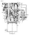
- FIG. 1 illustrates a belt type turret according to an embodiment of the invention
- FIGS. 2 and 3 are partially enlarged views of FIG. 1 ;
- FIG. 4 is a partially enlarged view of FIG. 1 where the spline shaft is advanced and tooth-engaged with an indexing spindle, according to the invention.
- FIG. 5 is a partially enlarged view of FIG. 1 where the spline shaft is retracted and tooth-engaged with a pulley d, according to the invention.
- FIG. 1 illustrates a belt type turret according to an embodiment of the invention
- FIGS. 2 and 3 are partially enlarged views of FIG. 1
- the belt type tool turret according to the invention includes a motor 1 for generating a driving force and having a motor shaft 2 formed therein; a center pulley 30 connected to the motor shaft 2, a pulley a 31 which is connected with the center pulley 30 by means of a belt a 40 and to which the motor 1 power is transferred, a drive shaft a 5 rotatably coupled to the pulley a 31, a first eccentric housing 3 formed at the outside of the drive shaft a 5 so as to have a certain degree of eccentricity, a pulley b 32 coupled to one side of the drive shaft a 5, a pulley c 33 connected with the pulley b 32 through a belt b 41 to transfer a power, the pulley c having a spline formed therein, a pulley d 34 formed at one side of the
- the tool replacement driver unit is configured to transfer a driving power to the disk 4 for the purpose of tool-replacement, except that the power generated from the motor 1 is transferred to the rotating tool driver unit 60 in the same manner.
- the tool replacement driver unit includes a pivotable curvic coupling 14 which is gear-engaged with a pinion gear 13 for and to which a power is transferred, a disk flange 28 fixedly coupled to the pivotable curvic coupling 14 by means of a bolt 43, a disk 4 fixedly coupled to the disk flange 28 by means of another bolt 44, and a fixing curvic coupling 15 and a piston curvic coupling 16 for fixing the disk 4 so as not to rotate.
- the rotating tool driver unit is configured to transfer a driving power to a rotating tool 26 for the purpose of driving the rotating tool 26, except that the power generated from the motor 1 is transferred to the tool replacement driver unit in the same way.
- the rotating tool driver unit includes a socket 21 coupled to a key groove of a shaft 19, a bevel gear a 23a coupled to the socket 21 by means of a bolt 45, a bevel gear b 23b pairing with the bevel gear a 23a, a drive shaft b 24 installed by passing through the bevel gear b 23b, and a tool driving shaft 25 for receiving a power by the drive shaft b 24 and transferring the power to a rotating tool 26.
- the eccentric housing 3 is eccentrically formed with a certain degree of eccentricity with respect to the absolute center line.
- a plurality of bearings (not indicated by reference numerals) is formed inside of the eccentric housing 3, into which a drive shaft a 5 is inserted to contact the bearing to rotate.
- another eccentric housing 29 is also eccentrically formed with a certain degree of eccentricity with respect to the absolute center line.
- a plurality of bearings (not indicated by reference numerals) is formed inside of the eccentric housing 29, where an indexing spindle 12 is formed and contacts the bearing to rotate.
- the tool turret according to the invention requires a distance adjustment between gears by which a power is transferred, during assembling, in order to reduce noises.
- a change in the distance between rotating shafts, caused by the distance adjustment, is nullified by tension adjustment of belts.
- a distance adjustment between the pinion gear 13 and the pivotable curvic coupling 14 is carried out by fixing the eccentric housing 29 in an optimum position while turning the eccentric housing 29.
- a change in the tension of the belt b 41, which has been incurred by the distance adjustment, is adjusted by turning the eccentric housing 3.
- a change in the tension of the belt a 40 is adjusted using a motor bracket 48. That is, if the tension of the belt a 40 is low, the motor bracket 48 is moved to the left in the figures. In the opposite case, the motor bracket 48 is moved to the right in the figures and then fixed there by means of a fastener bolt 49.
- the tension of the timing belt 42 is adjusted using an idle gear 27.
- the power transfer is carried out mostly by means of a belt, and the tension adjustment of the belt is required.
- the tension of the belt a 40 is adjusted by changing the position of the motor bracket 48, and the tension of the belt b 41 is adjusted by means of the eccentric housing 3.
- a pulley d 34 Formed at one side of the pulley c 33 is a pulley d 34. Both are far away from each other to independently rotate without interfering with each other. That is, even if the pulley c 33 rotates, the pulley d 34 does not rotate unless the spline shaft 7 operates.
- an external spline Formed in the outer circumferential face of the spline shaft 7 is an external spline, and formed in the inner face of the indexing spindle 12 is an internal spline 12a, which is tooth-engaged with the external spline.
- the spline shaft 7 is capable of reciprocating by means of a piston 8 formed at the rear side (to the motor side). The traveling distance is the same as that of the piston 8. Therefore, the spline shaft 7 is capable of being attached to and detached from the indexing spindle 12 so as to transfer or interrupt a rotating power to the indexing spindle 12.
- the external spline formed in the spline shaft 7 is formed to the extent of hatched portion in FIGS. 4 and 5 .
- the spline shaft 7 has advanced to be tooth-engaged with the internal spline 12a of the indexing spindle 12, but not engaged with the pulley d 34.
- the spline shaft 7 has retracted to be tooth-engaged with the pulley d 34, but not engaged with the indexing spindle 12.
- the external spline of the spline shaft 7 is always tooth-engaged with the pulley c 33, regardless of the advancement or retraction thereof, to receive a power.
- the external spline of the spline shaft repeats tooth-engagement with and release from the pulley d 34. Consequently, if the spline shaft 7 is advanced to be tooth-engaged with a spline formed inside of the indexing spindle 12, the rotating power is transferred towards the indexing spindle 12. On the contrary, if it is retracted to be released from the spline formed inside of the indexing spindle 12, the rotating power is transferred towards the shaft 19.
- the external spline of the spline shaft 7 is tooth-engaged with the internal spline formed inside of the pulley d 34 and thus the rotating power is being transferred to the pulley d 34. That is, if the rotating power is transferred to the pulley d 34, the pulley e 35 engaged through a timing belt 42 comes to receive the rotating power. Thus, the shaft 19, which is insert-coupled to the pulley e 35 by means of a locking element 20, comes to rotate.
- the shaft 19 is provided for transferring a rotating power to the rotating tool 26.
- the power transferred to the shaft 19 is transferred to a socket 21 formed inside of a gear box 22.
- the power is transferred to a bevel gear a 23a via the socket 21, and then transferred to the tool driving shaft 25 via a drive shaft b 24, which is insert-coupled to a bevel gear b 23 engaged with the bevel gear a 23a, thereby consequently driving the rotating tool 26.
- an idle gear is formed between the pulley d 34 and the pulley e 35. That is, since the pulley d 34 and the pulley e 35 are coupled inside of a body, its center cannot be easily moved. Thus, it is preferable that tension adjustment is performed using the idle gear 27.
- the spline shaft 7 needs, in its outside, a component for supporting the spline shaft 7 to avoid trembling during rotation. As shown in the figures, for this purpose, a needle bearing 50 can be formed at the upper and lower portions of the spline shaft 7.
- the cylinder 9 is fixed to a cylinder bracket 6, which is fixed to the body by means of a fixing bolt 47.
- Rotation of the motor 1 is transferred to the motor shaft 2, and then to the center pulley 30 coupled with the motor shaft 2.
- the power transferred to the center pulley 30 is transferred to the pulley a 31 by means of the belt a 40.
- the power transferred to the pulley a 31 is transferred to the drive shaft a 5, then to the pulley b 32, and then to the pulley b 41 through the belt b 41.
- the power transferred to the pulley c 33 is transferred to the spline shaft 7.
- the spline shaft 7 has advanced, it is coupled to the internal spline formed in the indexing spindle 12. If the spline shaft 7 has retracted, it is coupled to the internal spline formed in the pulley d 34.
- the spline shaft 7 is advanced or retracted by a piston 8. If a pneumatic pressure (air pressure) is applied to a first flow passageway 10, the spline shaft 7 is retracted towards the motor. On the contrary, if a pneumatic pressure is applied to a second flow passageway 11, the spline shaft 7 is advanced toward the indexing spindle 12.
- a pneumatic pressure air pressure
- the spline shaft 7 rotates the indexing spindle 12 and the pinion gear 13 coupled to the indexing spindle 12 comes to rotate.
- the rotating power is transferred to the pivotable curvic coupling 14, which is tooth-engaged with the pinion gear 13.
- the disk flange 28 coupled to the pivotable curvic coupling 14 comes to rotate.
- the disk 4 is also coupled to the disk flange 28 and thus comes to rotate such that a tool replacement can be performed.
- the distance adjustment between the pinion gear 13 and the pivotable curvic coupling 14 is carried out by another eccentric housing 29, thereby enabling to be assembled at an optimum position capable of providing for a solid engagement and reduced noises.
- the tool driving operation will be explained.
- the spline shaft 7 rotates the pulley d 34.
- the power transferred to the pulley d 34 is transferred to the pulley e 35 by means of the timing belt 42 to thereby rotate the shaft 19. Consequently, the power transferred to the shaft 19 is transferred towards the rotating tool 26 via the gear box 22, as described above.
- the pulley a 31 is formed in the motor shaft 2 formed in the motor 1 and the drive shaft a 5 to transfer the power by means of the belt a 40.
- Another pulley b 32 is formed at the other side of the drive shaft a 5.
- the pulley c 33 receives the power from the pulley b 32 through the belt b 41.
- Formed at one side of the pulley c 33 is the pulley d 34 for transferring the power to the shaft 19 for tool driving.
- the internal spline is formed in the indexing spindle 12 formed at one side of the pulley d 34.
- the spline shaft 7 reciprocates along the pulley c 33, the pulley d 34 and the spline formed inside of the indexing spindle 12.
- the power is transferred or interrupted by means of forward and backward reciprocal movement of the spline shaft 7.
- the engagement between the pivotable curvic coupling 14 and the pinion gear 13 is adjusted by means of the eccentric housing 29.
- the tension of the belt b 41 is adjusted using another eccentric housing 3.
- the tension of the belt a 40 is adjusted by controlling the position of the motor bracket 48. That is, the belt tensions and the distances between the gears can be finely adjusted using the eccentric housings 3 and 29.
- the power transfer system of the motor is formed mostly of belts, thereby enabling to reduce noises of the tool turret and to save the assembling time and cost.
- a spline shaft having a spline is formed to thereby enable to transfer the power in more smooth way.
Landscapes
- Engineering & Computer Science (AREA)
- Mechanical Engineering (AREA)
- Transmission Devices (AREA)
- Cutting Tools, Boring Holders, And Turrets (AREA)
- Gripping On Spindles (AREA)
- Punching Or Piercing (AREA)
Priority Applications (1)
| Application Number | Priority Date | Filing Date | Title |
|---|---|---|---|
| PL07017676T PL1900475T3 (pl) | 2006-09-13 | 2007-09-10 | Głowica narzędziowa typu pasowego |
Applications Claiming Priority (1)
| Application Number | Priority Date | Filing Date | Title |
|---|---|---|---|
| KR1020060088594A KR100718060B1 (ko) | 2006-09-13 | 2006-09-13 | 벨트로 동력을 전달하는 터렛공구대 및 터렛공구대의동력전달방법 |
Publications (2)
| Publication Number | Publication Date |
|---|---|
| EP1900475A1 EP1900475A1 (en) | 2008-03-19 |
| EP1900475B1 true EP1900475B1 (en) | 2009-11-11 |
Family
ID=38270721
Family Applications (1)
| Application Number | Title | Priority Date | Filing Date |
|---|---|---|---|
| EP07017676A Not-in-force EP1900475B1 (en) | 2006-09-13 | 2007-09-10 | Belt type tool turret |
Country Status (5)
| Country | Link |
|---|---|
| EP (1) | EP1900475B1 (pl) |
| KR (1) | KR100718060B1 (pl) |
| AT (1) | ATE448048T1 (pl) |
| DE (1) | DE602007003158D1 (pl) |
| PL (1) | PL1900475T3 (pl) |
Families Citing this family (9)
| Publication number | Priority date | Publication date | Assignee | Title |
|---|---|---|---|---|
| KR100938873B1 (ko) * | 2007-08-23 | 2010-01-27 | 이더블유에스 코리아 주식회사 | 원모터 액슬타입의 터렛공구대 |
| KR100951892B1 (ko) | 2008-07-29 | 2010-04-12 | 이더블유에스 코리아 주식회사 | 원모터형 터렛공구대 |
| KR101535298B1 (ko) * | 2008-11-17 | 2015-07-09 | 두산인프라코어 주식회사 | 선반용 단일 모터 공구대 |
| KR101014785B1 (ko) * | 2009-02-26 | 2011-02-14 | 이더블유에스 코리아 주식회사 | 터렛공구대 |
| IT1394351B1 (it) * | 2009-05-06 | 2012-06-06 | Worldmec S R L | Macchina fresatrice, particolarmente per lavorazioni su piu' facce. |
| KR101081284B1 (ko) * | 2011-05-04 | 2011-11-08 | 구삼영 | 밀링머신 고속 부착장치 |
| CN106584180A (zh) * | 2017-02-10 | 2017-04-26 | 中山市溢丰达机械设备有限公司 | 四头自动换刀主轴机构及多头自动换刀主轴机构 |
| CN111843794B (zh) * | 2020-09-23 | 2021-01-05 | 佛山市后浪科技有限公司 | 一种工件固定治具 |
| KR102745277B1 (ko) | 2022-11-18 | 2024-12-23 | (주)스마트공작기계코리아 | 터렛 조립체 |
Family Cites Families (5)
| Publication number | Priority date | Publication date | Assignee | Title |
|---|---|---|---|---|
| JPH06743A (ja) * | 1992-06-20 | 1994-01-11 | Okuma Mach Works Ltd | 工具割出装置 |
| IL138023A (en) * | 2000-08-23 | 2003-03-12 | Bronco Construction Equipment | Adapter for power tools |
| JP2003071615A (ja) * | 2001-08-30 | 2003-03-12 | Mori Seiki Co Ltd | タレット刃物台 |
| JP4378449B2 (ja) * | 2002-02-20 | 2009-12-09 | 東洋紡績株式会社 | 吸着材およびその製造方法 |
| JP4082716B2 (ja) * | 2002-07-29 | 2008-04-30 | 東北電力株式会社 | 遠隔操作工具 |
-
2006
- 2006-09-13 KR KR1020060088594A patent/KR100718060B1/ko not_active Expired - Fee Related
-
2007
- 2007-09-10 PL PL07017676T patent/PL1900475T3/pl unknown
- 2007-09-10 AT AT07017676T patent/ATE448048T1/de not_active IP Right Cessation
- 2007-09-10 EP EP07017676A patent/EP1900475B1/en not_active Not-in-force
- 2007-09-10 DE DE602007003158T patent/DE602007003158D1/de active Active
Also Published As
| Publication number | Publication date |
|---|---|
| ATE448048T1 (de) | 2009-11-15 |
| PL1900475T3 (pl) | 2010-06-30 |
| DE602007003158D1 (de) | 2009-12-24 |
| EP1900475A1 (en) | 2008-03-19 |
| KR100718060B1 (ko) | 2007-05-14 |
Similar Documents
| Publication | Publication Date | Title |
|---|---|---|
| EP1900475A1 (en) | Belt type tool turret | |
| US9017206B2 (en) | Gear device | |
| US11052528B2 (en) | Power tool | |
| JP2000317854A (ja) | インパクト回転工具 | |
| CN103649587B (zh) | 齿轮装置 | |
| JP2006297541A (ja) | 工作機械の回転軸装置 | |
| US10797558B2 (en) | Electric retracting unit for electric retractable view device for vehicle | |
| EP1808267B1 (en) | Tool turret | |
| US7677325B2 (en) | Pneumatic tool | |
| GB2631033A (en) | Integrated joint power unit and legged robot using same | |
| JP2009273846A (ja) | 工業用ミシンの駆動装置 | |
| US8905886B2 (en) | Gear device | |
| JPH09254046A (ja) | 電動ドライバー | |
| US9879719B2 (en) | Supporting structure for gear of outboard motor | |
| KR100951892B1 (ko) | 원모터형 터렛공구대 | |
| US20050119098A1 (en) | Motorized roller | |
| KR100568951B1 (ko) | 트랜스퍼 크레인용 감속기 | |
| KR101505414B1 (ko) | 감속기 엔드커버 | |
| JP4948844B2 (ja) | 回転工具タレット | |
| US20080282840A1 (en) | Drive Shaft Moving Device | |
| CN115803543B (zh) | 带变速器马达 | |
| US20100269614A1 (en) | Deceleration device for power turret clutch | |
| US6015336A (en) | Grinding apparatus | |
| EP4019804A1 (en) | Short-axle large-speed-ratio gear set structure | |
| JP2005270298A (ja) | リクライニング装置 |
Legal Events
| Date | Code | Title | Description |
|---|---|---|---|
| PUAI | Public reference made under article 153(3) epc to a published international application that has entered the european phase |
Free format text: ORIGINAL CODE: 0009012 |
|
| AK | Designated contracting states |
Kind code of ref document: A1 Designated state(s): AT BE BG CH CY CZ DE DK EE ES FI FR GB GR HU IE IS IT LI LT LU LV MC MT NL PL PT RO SE SI SK TR |
|
| AX | Request for extension of the european patent |
Extension state: AL BA HR MK YU |
|
| 17P | Request for examination filed |
Effective date: 20080919 |
|
| AKX | Designation fees paid |
Designated state(s): AT BE BG CH CY CZ DE DK EE ES FI FR GB GR HU IE IS IT LI LT LU LV MC MT NL PL PT RO SE SI SK TR |
|
| GRAP | Despatch of communication of intention to grant a patent |
Free format text: ORIGINAL CODE: EPIDOSNIGR1 |
|
| GRAS | Grant fee paid |
Free format text: ORIGINAL CODE: EPIDOSNIGR3 |
|
| GRAA | (expected) grant |
Free format text: ORIGINAL CODE: 0009210 |
|
| AK | Designated contracting states |
Kind code of ref document: B1 Designated state(s): AT BE BG CH CY CZ DE DK EE ES FI FR GB GR HU IE IS IT LI LT LU LV MC MT NL PL PT RO SE SI SK TR |
|
| REG | Reference to a national code |
Ref country code: GB Ref legal event code: FG4D |
|
| REG | Reference to a national code |
Ref country code: CH Ref legal event code: EP |
|
| REG | Reference to a national code |
Ref country code: IE Ref legal event code: FG4D |
|
| REF | Corresponds to: |
Ref document number: 602007003158 Country of ref document: DE Date of ref document: 20091224 Kind code of ref document: P |
|
| NLV1 | Nl: lapsed or annulled due to failure to fulfill the requirements of art. 29p and 29m of the patents act | ||
| LTIE | Lt: invalidation of european patent or patent extension |
Effective date: 20091111 |
|
| PG25 | Lapsed in a contracting state [announced via postgrant information from national office to epo] |
Ref country code: PT Free format text: LAPSE BECAUSE OF FAILURE TO SUBMIT A TRANSLATION OF THE DESCRIPTION OR TO PAY THE FEE WITHIN THE PRESCRIBED TIME-LIMIT Effective date: 20100311 Ref country code: FI Free format text: LAPSE BECAUSE OF FAILURE TO SUBMIT A TRANSLATION OF THE DESCRIPTION OR TO PAY THE FEE WITHIN THE PRESCRIBED TIME-LIMIT Effective date: 20091111 Ref country code: SE Free format text: LAPSE BECAUSE OF FAILURE TO SUBMIT A TRANSLATION OF THE DESCRIPTION OR TO PAY THE FEE WITHIN THE PRESCRIBED TIME-LIMIT Effective date: 20091111 Ref country code: LT Free format text: LAPSE BECAUSE OF FAILURE TO SUBMIT A TRANSLATION OF THE DESCRIPTION OR TO PAY THE FEE WITHIN THE PRESCRIBED TIME-LIMIT Effective date: 20091111 Ref country code: IS Free format text: LAPSE BECAUSE OF FAILURE TO SUBMIT A TRANSLATION OF THE DESCRIPTION OR TO PAY THE FEE WITHIN THE PRESCRIBED TIME-LIMIT Effective date: 20100311 Ref country code: ES Free format text: LAPSE BECAUSE OF FAILURE TO SUBMIT A TRANSLATION OF THE DESCRIPTION OR TO PAY THE FEE WITHIN THE PRESCRIBED TIME-LIMIT Effective date: 20100222 |
|
| PG25 | Lapsed in a contracting state [announced via postgrant information from national office to epo] |
Ref country code: SI Free format text: LAPSE BECAUSE OF FAILURE TO SUBMIT A TRANSLATION OF THE DESCRIPTION OR TO PAY THE FEE WITHIN THE PRESCRIBED TIME-LIMIT Effective date: 20091111 Ref country code: LV Free format text: LAPSE BECAUSE OF FAILURE TO SUBMIT A TRANSLATION OF THE DESCRIPTION OR TO PAY THE FEE WITHIN THE PRESCRIBED TIME-LIMIT Effective date: 20091111 Ref country code: CY Free format text: LAPSE BECAUSE OF FAILURE TO SUBMIT A TRANSLATION OF THE DESCRIPTION OR TO PAY THE FEE WITHIN THE PRESCRIBED TIME-LIMIT Effective date: 20091111 |
|
| PG25 | Lapsed in a contracting state [announced via postgrant information from national office to epo] |
Ref country code: BE Free format text: LAPSE BECAUSE OF FAILURE TO SUBMIT A TRANSLATION OF THE DESCRIPTION OR TO PAY THE FEE WITHIN THE PRESCRIBED TIME-LIMIT Effective date: 20091111 Ref country code: AT Free format text: LAPSE BECAUSE OF FAILURE TO SUBMIT A TRANSLATION OF THE DESCRIPTION OR TO PAY THE FEE WITHIN THE PRESCRIBED TIME-LIMIT Effective date: 20091111 |
|
| PG25 | Lapsed in a contracting state [announced via postgrant information from national office to epo] |
Ref country code: EE Free format text: LAPSE BECAUSE OF FAILURE TO SUBMIT A TRANSLATION OF THE DESCRIPTION OR TO PAY THE FEE WITHIN THE PRESCRIBED TIME-LIMIT Effective date: 20091111 Ref country code: DK Free format text: LAPSE BECAUSE OF FAILURE TO SUBMIT A TRANSLATION OF THE DESCRIPTION OR TO PAY THE FEE WITHIN THE PRESCRIBED TIME-LIMIT Effective date: 20091111 Ref country code: RO Free format text: LAPSE BECAUSE OF FAILURE TO SUBMIT A TRANSLATION OF THE DESCRIPTION OR TO PAY THE FEE WITHIN THE PRESCRIBED TIME-LIMIT Effective date: 20091111 Ref country code: BG Free format text: LAPSE BECAUSE OF FAILURE TO SUBMIT A TRANSLATION OF THE DESCRIPTION OR TO PAY THE FEE WITHIN THE PRESCRIBED TIME-LIMIT Effective date: 20100211 |
|
| PG25 | Lapsed in a contracting state [announced via postgrant information from national office to epo] |
Ref country code: SK Free format text: LAPSE BECAUSE OF FAILURE TO SUBMIT A TRANSLATION OF THE DESCRIPTION OR TO PAY THE FEE WITHIN THE PRESCRIBED TIME-LIMIT Effective date: 20091111 |
|
| PLBE | No opposition filed within time limit |
Free format text: ORIGINAL CODE: 0009261 |
|
| STAA | Information on the status of an ep patent application or granted ep patent |
Free format text: STATUS: NO OPPOSITION FILED WITHIN TIME LIMIT |
|
| 26N | No opposition filed |
Effective date: 20100812 |
|
| PG25 | Lapsed in a contracting state [announced via postgrant information from national office to epo] |
Ref country code: GR Free format text: LAPSE BECAUSE OF FAILURE TO SUBMIT A TRANSLATION OF THE DESCRIPTION OR TO PAY THE FEE WITHIN THE PRESCRIBED TIME-LIMIT Effective date: 20100212 |
|
| PG25 | Lapsed in a contracting state [announced via postgrant information from national office to epo] |
Ref country code: MC Free format text: LAPSE BECAUSE OF NON-PAYMENT OF DUE FEES Effective date: 20100930 |
|
| PGFP | Annual fee paid to national office [announced via postgrant information from national office to epo] |
Ref country code: CZ Payment date: 20110308 Year of fee payment: 4 |
|
| REG | Reference to a national code |
Ref country code: FR Ref legal event code: ST Effective date: 20110531 |
|
| REG | Reference to a national code |
Ref country code: DE Ref legal event code: R119 Ref document number: 602007003158 Country of ref document: DE Effective date: 20110401 |
|
| PG25 | Lapsed in a contracting state [announced via postgrant information from national office to epo] |
Ref country code: IE Free format text: LAPSE BECAUSE OF NON-PAYMENT OF DUE FEES Effective date: 20100910 Ref country code: DE Free format text: LAPSE BECAUSE OF NON-PAYMENT OF DUE FEES Effective date: 20110401 Ref country code: FR Free format text: LAPSE BECAUSE OF NON-PAYMENT OF DUE FEES Effective date: 20100930 |
|
| PG25 | Lapsed in a contracting state [announced via postgrant information from national office to epo] |
Ref country code: MT Free format text: LAPSE BECAUSE OF FAILURE TO SUBMIT A TRANSLATION OF THE DESCRIPTION OR TO PAY THE FEE WITHIN THE PRESCRIBED TIME-LIMIT Effective date: 20091111 |
|
| PG25 | Lapsed in a contracting state [announced via postgrant information from national office to epo] |
Ref country code: PL Free format text: LAPSE BECAUSE OF NON-PAYMENT OF DUE FEES Effective date: 20100910 |
|
| REG | Reference to a national code |
Ref country code: PL Ref legal event code: LAPE |
|
| PG25 | Lapsed in a contracting state [announced via postgrant information from national office to epo] |
Ref country code: CZ Free format text: LAPSE BECAUSE OF NON-PAYMENT OF DUE FEES Effective date: 20110910 |
|
| REG | Reference to a national code |
Ref country code: CH Ref legal event code: PL |
|
| PG25 | Lapsed in a contracting state [announced via postgrant information from national office to epo] |
Ref country code: IT Free format text: LAPSE BECAUSE OF NON-PAYMENT OF DUE FEES Effective date: 20110910 |
|
| PG25 | Lapsed in a contracting state [announced via postgrant information from national office to epo] |
Ref country code: CH Free format text: LAPSE BECAUSE OF NON-PAYMENT OF DUE FEES Effective date: 20110930 Ref country code: LI Free format text: LAPSE BECAUSE OF NON-PAYMENT OF DUE FEES Effective date: 20110930 |
|
| PG25 | Lapsed in a contracting state [announced via postgrant information from national office to epo] |
Ref country code: NL Free format text: LAPSE BECAUSE OF FAILURE TO SUBMIT A TRANSLATION OF THE DESCRIPTION OR TO PAY THE FEE WITHIN THE PRESCRIBED TIME-LIMIT Effective date: 20091111 Ref country code: LU Free format text: LAPSE BECAUSE OF NON-PAYMENT OF DUE FEES Effective date: 20100910 Ref country code: HU Free format text: LAPSE BECAUSE OF FAILURE TO SUBMIT A TRANSLATION OF THE DESCRIPTION OR TO PAY THE FEE WITHIN THE PRESCRIBED TIME-LIMIT Effective date: 20100512 |
|
| PGRI | Patent reinstated in contracting state [announced from national office to epo] |
Ref country code: IT Effective date: 20120630 |
|
| PGFP | Annual fee paid to national office [announced via postgrant information from national office to epo] |
Ref country code: IT Payment date: 20121115 Year of fee payment: 6 Ref country code: GB Payment date: 20121116 Year of fee payment: 6 |
|
| PG25 | Lapsed in a contracting state [announced via postgrant information from national office to epo] |
Ref country code: TR Free format text: LAPSE BECAUSE OF FAILURE TO SUBMIT A TRANSLATION OF THE DESCRIPTION OR TO PAY THE FEE WITHIN THE PRESCRIBED TIME-LIMIT Effective date: 20091111 |
|
| GBPC | Gb: european patent ceased through non-payment of renewal fee |
Effective date: 20130910 |
|
| PG25 | Lapsed in a contracting state [announced via postgrant information from national office to epo] |
Ref country code: GB Free format text: LAPSE BECAUSE OF NON-PAYMENT OF DUE FEES Effective date: 20130910 |
|
| PG25 | Lapsed in a contracting state [announced via postgrant information from national office to epo] |
Ref country code: IT Free format text: LAPSE BECAUSE OF NON-PAYMENT OF DUE FEES Effective date: 20130910 |