EP1900304B1 - Fitting for a corner cupboard - Google Patents
Fitting for a corner cupboard Download PDFInfo
- Publication number
- EP1900304B1 EP1900304B1 EP07015137A EP07015137A EP1900304B1 EP 1900304 B1 EP1900304 B1 EP 1900304B1 EP 07015137 A EP07015137 A EP 07015137A EP 07015137 A EP07015137 A EP 07015137A EP 1900304 B1 EP1900304 B1 EP 1900304B1
- Authority
- EP
- European Patent Office
- Prior art keywords
- upper support
- section
- column
- support section
- mounting according
- Prior art date
- Legal status (The legal status is an assumption and is not a legal conclusion. Google has not performed a legal analysis and makes no representation as to the accuracy of the status listed.)
- Active
Links
- 238000003780 insertion Methods 0.000 claims description 5
- 230000037431 insertion Effects 0.000 claims description 5
- 230000008878 coupling Effects 0.000 claims description 4
- 238000010168 coupling process Methods 0.000 claims description 4
- 238000005859 coupling reaction Methods 0.000 claims description 4
- 230000000284 resting effect Effects 0.000 claims 1
- 238000011161 development Methods 0.000 description 4
- 230000018109 developmental process Effects 0.000 description 4
- 238000003032 molecular docking Methods 0.000 description 2
- 230000001680 brushing effect Effects 0.000 description 1
- 238000007654 immersion Methods 0.000 description 1
- 230000013011 mating Effects 0.000 description 1
Images


Classifications
-
- A—HUMAN NECESSITIES
- A47—FURNITURE; DOMESTIC ARTICLES OR APPLIANCES; COFFEE MILLS; SPICE MILLS; SUCTION CLEANERS IN GENERAL
- A47B—TABLES; DESKS; OFFICE FURNITURE; CABINETS; DRAWERS; GENERAL DETAILS OF FURNITURE
- A47B49/00—Revolving cabinets or racks; Cabinets or racks with revolving parts
- A47B49/004—Cabinets with compartments provided with trays revolving on a vertical axis
- A47B49/006—Corner cabinets
Definitions
- the invention relates to a fitting for a corner cabinet, in particular fareck Drue Drue Drue Drue Drue, with a rotatable about a Drehachsline column having a lower pillar part and a telescopically with the lower pillar part upper pillar part, and having an upper and a lower support member for a door, said form two support parts together with the column in the assembled state, a rotary unit.
- Such a fitting for a corner cabinet is for example from the DE 298 23 024 known, in which case the column is variable in length and of a main tube and a coaxial to the main tube end assembled with the main tube and thereby in the axial direction in front of the main tube projecting extension rod is formed, wherein the longitudinal position of the extension rod relative to the main tube is adjustable and lockable ,
- a corner cabinet is described, with a rotatable carousel in the cabinet body, which has a telescopic rotary column, which is mounted on an upper cabinet cover and the bottom of the cabinet.
- the rotary column carries a lower and an upper fitting part, wherein the upper fitting part can be fixed to a telescopic part of the rotary column and can be displaced together with it.
- a corner cabinet with a conventional fitting is also off DE-20 2005 005 888 U1 known.
- the object of the invention is to provide a fitting of the type mentioned above, which has the greatest possible variability and high stability when attached to corner cabinets of different cabinet height and allows a reduction of the transport volume.
- the fitting according to the invention is characterized in that the upper support member is rotatably supported or mounted on a pivot bearing device connected or connectable with an upper cabinet cover, and that the upper column part is detachably connectable to the upper support member, so that the column in the mounted state over the Upper support member is rotatably mounted on the pivot bearing device.
- the upper support member which may also be referred to as the upper door holder, is therefore not supported by the pillar, but by the pivot bearing device.
- the telescoping of the column can therefore be carried out relatively comfortably, since the sitting on the pivot bearing device upper support member is not moved. The handling is thus easier.
- the upper support part is seated on a bearing element connected to a support device to be fixedly mounted in the corner cabinet.
- support means for example, serve a so-called bearing cross.
- other carrier geometries or embodiments can also be used.
- the bearing element is formed by a bearing journal, on which the upper support member sits.
- the bearing element is formed by a bearing sleeve which engages around a projection formed on the upper support part.
- the bearing pin is non-rotatably arranged on the support means and the upper support member is rotatably mounted on the bearing journal.
- the journal and the upper support member it would also be conceivable to non-rotatably connect the journal and the upper support member and then to rotatably arrange the journal on the support apparatus.
- the upper column part is rotatably connected via coupling means with the upper support member.
- a coupling means may be provided for plugging together upper column part and upper support member.
- the plug-in device may eccentrically have the Drehachsline arranged plug-in pins, which are associated with corresponding plug-in holes.
- the eccentric arrangement prevents rotation of the upper column part relative to the upper support member.
- the plug-in pins can be designed such that a tool-free locking between the upper support member and the upper column part is possible.
- the plug-in pins are arranged on the upper pillar part and the plug-in holes on the upper support part.
- a securing device may be provided, which may have, for example, an axially fixed seated on the bearing pin retaining ring.
- the axial clearance may exist between the support means and the upper support member and / or between the upper support member and the upper pillar member.
- a lift-off can be provided which prevents the upper pillar part dissolves when lifting on the support means of the upper support member.
- the lift-out can be formed by the latched with the upper support member spigot or by a separate fuse element, for example in the form of a safety screw.
- the corner cupboard 11 of a fitted kitchen contains a carousel 12, which is formed by a Eck Obeschlag 13, at least one shelf 14 and a door 15, wherein the at least one shelf 14 and the door 15 is held by Eck Obeschlag 13.
- the door 15 is formed by two separate door leaves 15a, 15b, which are movable relative to each other when opening.
- the Eck andschlag 13 has a in-use position, that is in the built-in corner cabinet 11 state vertically aligned pillar 16, which is stored above in the manner described below and below the bottom of the cabinet.
- the column 16 is formed as a central, to a Drehachsline 17 coaxial rotary column.
- a U-shaped column which could also be referred to as a carousel frame, in which case horizontally extending bearing arms are rotatably mounted.
- the column 16 has a lower column part 18 and an upper column part 19 telescopically connected to the lower column part 18, the two column parts 18, 19 having different diameters from each other.
- the upper column portion 19 has a smaller diameter than the lower column portion 18.
- the corner cabinet 12 further has an overhanging cabinet opening 20, which is assigned to one of the two already mentioned door panels 15a, 15b, so far double-leaf door.
- the two door leaves 15a, 15b are in the closed position, when they close the cabinet opening 20, approximately at right angles to each other.
- Each wing 15a, 15b of the adjacent side wall 21a, 21b forms a right angle, wherein the one door 15a engages over the end face of a side wall 21a and the other door 15b the end face of the other side wall 21b.
- a door may be provided, the door leaves are aligned in angular stable position to each other and are pressed in this position to open the door radially inward.
- a door may also be provided, which consists of a single door element which extends across the cabinet opening, this closing in the closed position extends. To open the door element is then pressed radially inward.
- the at least one shelf 14 does not extend over a full circumference. Rather, it has a suitably over a smaller angle than 90 ° going sector-shaped cutout, which in the two door wings 15a, 15b is arranged. The doorway formed by the two door wings 15a, 15b projects into this cutout.
- the two door leaves 15a, 15b are pressed inward to open in the open position.
- the two separate door leaves 15a, 15b perform a mirror-image movement with respect to the bisector 50 of the doorway, which consists of a fold-in movement reducing the angle between the two door leaves 15a, 15b and a retraction movement along the angle bisector 50 superimposed thereon.
- the door wings 15a, 15b pass further into the cutout which, at least as far as it is necessary for the immersion of the door leaves 15a, 15b, is also free of other parts.
- the two door leaves 15a, 15b of the side walls 21a, 21b of the corner cupboard 11 are free.
- the door wings 15a, 15b reach inwards and are optionally lowered at the same time, so that the carousel 12 can be rotated in the corner cabinet 11 without the door leaves 15a, 15b brushing against the side walls 21a, 21b.
- each point of the at least one shelf 14 can be rotated forward to the cabinet opening 20, so that objects can be set or removed anywhere.
- the corner cabinet fitting further comprises a lower and an upper support member 22, 23, wherein the lower support member 22 is fixed to the lower pillar part
- a control linkage is arranged, with which the door leaf movement is controlled when opening and closing.
- the control linkage is in particular to the EP 0 317 737 B1 directed.
- corner cabinet 11 also still includes an example formed by a worktop upper cabinet cover 24 to which a support means in the form of a bearing cross 25 is mounted on the underside.
- the bearing cross 25 has a plurality of bearing arms 26 which are connected to the side walls 21a, 21b and with a Eck jetsterwand.
- the upper support member 23 is rotatably supported on a pivot bearing device 28 connected to the upper cabinet cover 24.
- the pivot bearing device 28 belongs to the pivot bearing device 28 approximately in the middle of the bearing cross 25 arranged support plate 29 having a through hole 30.
- the bearing pin 31 is fixed or rotatably connected to the support plate 29.
- the protruding from the support plate 29 down part of the journal 31 is stepped and has a diameter-wide base portion 33 to the free end of the bearing pin 31 toward a smaller diameter slip-on portion 34 connects.
- a Traumsteckloch 35 located at the upper support member 23 a Traumsteckloch 35, via which the upper support member 23 is fitted onto the Aufsteckabrough 34 of the journal 31.
- a safety device 36 which has in particular a single axially fixed seated on the bearing pin 31 retaining ring 37.
- dash-dotted line variant shown by riveting the Aufsteckabiteses 34 a non-detachable connection between the bearing pin 31 and the upper support member 23 is made.
- the upper pillar part 23 is detachably connected to the upper support part 23, so that the pillar 16 is rotatably mounted on the pivot bearing device 28 via the upper support part 23 in the assembled state.
- plug-in device 38 for mating of upper column part 19 and upper support member 23 is provided, which eccentrically the Drehachsline 17 arranged plug-in pin 39, which are associated with corresponding plug holes 40.
- the longitudinal axes 45 of the plug-in pins 39 extend substantially parallel to the axis of rotation axis.
- the plug-in pins 39 are seated on a docking plate 41 connected in particular integrally therewith at the upper end of the upper column part 19.
- three plug-in pins 39 seated in particular at the same distance from one another on the docking plate 41 are provided. Corresponding to this are at the top Support member 23, the plug holes 40, for example, three in number.
- a respective plug-in pin 39 may be barb-like, with a central slot, so that the plug-in pin 39 is pressed together during insertion through the associated plug-in hole 40. After insertion, the plug pin 39 snaps back on, so that it is axially fixed against the insertion direction to the upper support member 23. Upper support member 23 and upper column member 19 are thus rotatably connected to each other.
Landscapes
- Cabinets, Racks, Or The Like Of Rigid Construction (AREA)
- Hinges (AREA)
- Casings For Electric Apparatus (AREA)
- Details Of Television Scanning (AREA)
- Holders For Apparel And Elements Relating To Apparel (AREA)
Abstract
Description
Die Erfindung betrifft einen Beschlag für einen Eckschrank, insbesondere Kücheneckschrank, mit einer um eine Drehachslinie drehbaren Säule, die ein unteres Säulenteil und ein teleskopartig mit dem unteren Säulenteil zusammengestecktes oberes Säulenteil aufweist, und mit einem oberen und einem unteren Tragteil für eine Tür, wobei die beiden Tragteile zusammen mit der Säule im montierten Zustand eine Dreheinheit bilden.The invention relates to a fitting for a corner cabinet, in particular Kücheneckschrank, with a rotatable about a Drehachslinie column having a lower pillar part and a telescopically with the lower pillar part upper pillar part, and having an upper and a lower support member for a door, said form two support parts together with the column in the assembled state, a rotary unit.
Ein derartiger Beschlag für einen Eckschrank ist beispielsweise aus der
In der
Ein Eckschrank mit einem konventionellen Beschlag ist auch aus
Aufgabe der Erfindung ist es, einen Beschlag der eingangs erwähnten Art zu schaffen, der größtmögliche Variabilität und hohe Stabilität bei Anbringung an Eckschränken unterschiedlicher Schrankhöhe aufweist sowie eine Reduzierung des Transportvolumens ermöglicht.The object of the invention is to provide a fitting of the type mentioned above, which has the greatest possible variability and high stability when attached to corner cabinets of different cabinet height and allows a reduction of the transport volume.
Diese Aufgabe wird durch einen Beschlag mit den Merkmalen des unabhängigen Anspruchs 1 gelöst. Weiterbildungen der Erfindung sind in den Unteransprüchen dargestellt.This object is achieved by a fitting with the features of the independent claim 1. Further developments of the invention are shown in the subclaims.
Der erfindungsgemäße Beschlag zeichnet sich dadurch aus, dass das obere Tragteil drehbar an einer mit einer oberen Schrankabdeckung verbundenen oder verbindbaren Drehlagereinrichtung lagerbar oder gelagert ist, und dass das obere Säulenteil lösbar mit dem oberen Tragteil verbindbar ist, so dass die Säule im montierten Zustand über das obere Tragteil drehbar an der Drehlagereinrichtung gelagert ist.The fitting according to the invention is characterized in that the upper support member is rotatably supported or mounted on a pivot bearing device connected or connectable with an upper cabinet cover, and that the upper column part is detachably connectable to the upper support member, so that the column in the mounted state over the Upper support member is rotatably mounted on the pivot bearing device.
Das obere Tragteil, das auch als oberer Türhalter bezeichnet werden kann, wird also nicht von der Säule, sondern von der Drehlagereinrichtung getragen. Das Teleskopieren der Säule kann also relativ komfortabel durchgeführt werden, da das an der Drehlagereinrichtung sitzende obere Tragteil nicht mitbewegt wird. Das Handling ist somit einfacher. Außerdem ergibt sich durch die Anbringung des oberen Tragteils an der Drehlagereinrichtung, die wiederum mit der oberen Schrankabdeckung verbunden ist, insgesamt ein relativ stabil aufgebauter Eckschrankbeschlag. Ein wichtiger Vorteil gegenüber dem eingangs erwähnten Stand der Technik ist die Reduzierung des Transportvolumens. Während bei dem in der
Bei einer Weiterbildung der Erfindung sitzt das obere Tragteil an einem mit einer feststehend im Eckschrank zu montierenden Trageinrichtung verbundenen Lagerelement. Als Trageinrichtung kann beispielsweise ein sogenanntes Lagerkreuz dienen. Es sind jedoch auch andere Trageinrichtungs-Geometrien bzw. Ausführungsformen einsetzbar.In a further development of the invention, the upper support part is seated on a bearing element connected to a support device to be fixedly mounted in the corner cabinet. As support means, for example, serve a so-called bearing cross. However, other carrier geometries or embodiments can also be used.
In bevorzugter Weise wird das Lagerelement von einem Lagerzapfen gebildet, auf dem das obere Tragteil sitzt. Alternativ ist es möglich, dass das Lagerelement von einer Lagerhülse gebildet wird, die einen am oberen Tragteil ausgebildeten Vorsprung umgreift.Preferably, the bearing element is formed by a bearing journal, on which the upper support member sits. Alternatively, it is possible that the bearing element is formed by a bearing sleeve which engages around a projection formed on the upper support part.
In besonders bevorzugter Weise ist der Lagerzapfen drehfest an der Trageinrichtung angeordnet und das obere Tragteil ist drehbar am Lagerzapfen gelagert. Prinzipiell wäre es jedoch auch denkbar, Lagerzapfen und oberes Tragteil drehfest miteinander zu verbinden und dann den Lagerzapfen drehbar an der Trageinrichtung anzuordnen.In a particularly preferred manner, the bearing pin is non-rotatably arranged on the support means and the upper support member is rotatably mounted on the bearing journal. In principle, however, it would also be conceivable to non-rotatably connect the journal and the upper support member and then to rotatably arrange the journal on the support apparatus.
Bei einer Weiterbildung der Erfindung ist das obere Säulenteil über Kopplungsmittel drehfest mit dem oberen Tragteil verbunden. Als Kopplungsmittel kann eine Steckeinrichtung zum Zusammenstecken von oberem Säulenteil und oberem Tragteil vorgesehen sein. Alternativ ist es auch möglich, oberes Säulenteil und oberes Tragteil miteinander zu verklemmen oder mittels einer Schraubeinrichtung zu verschrauben.In a further development of the invention, the upper column part is rotatably connected via coupling means with the upper support member. As a coupling means may be provided for plugging together upper column part and upper support member. Alternatively, it is also possible to clamp upper column part and upper support part together or to screw it by means of a screw.
Die Steckeinrichtung kann außermittig der Drehachslinie angeordnete Steckzapfen aufweisen, denen korrespondierende Stecklöcher zugeordnet sind. Die außermittige Anordnung verhindert ein Verdrehen des oberen Säulenteils gegenüber dem oberen Tragteil. Die Steckzapfen können derart ausgebildet sein, dass ein werkzeugloses Verrasten zwischen oberem Tragteil und oberem Säulenteil möglich ist. Besonders bevorzugt sind die Steckzapfen am oberen Säulenteil und die Stecklöcher am oberen Tragteil angeordnet.The plug-in device may eccentrically have the Drehachslinie arranged plug-in pins, which are associated with corresponding plug-in holes. The eccentric arrangement prevents rotation of the upper column part relative to the upper support member. The plug-in pins can be designed such that a tool-free locking between the upper support member and the upper column part is possible. Particularly preferably, the plug-in pins are arranged on the upper pillar part and the plug-in holes on the upper support part.
Um das obere Tragteil am Lagerzapfen axial zu sichern, kann eine Sicherungseinrichtung vorgesehen sein, die beispielsweise einen axial feststehend am Lagerzapfen sitzenden Sicherungsring aufweisen kann.In order to axially secure the upper support member on the bearing pin, a securing device may be provided, which may have, for example, an axially fixed seated on the bearing pin retaining ring.
Um zu verhindern, dass der Beschlag im in den Eckschrank eingebauten Zustand infolge von Maßungenauigkeiten unter Spannung steht; beispielsweise verursacht durch eine Durchbiegung der Trageinrichtung; kann axial zur Drehachslinie axiales Spiel vorliegen. Das axiale Spiel kann zwischen der Trageinrichtung und dem oberen Tragteil und/oder zwischen dem oberen Tragteil und dem oberen Säulenteil vorliegen.To prevent the fitting being under tension in the corner cabinet installed as a result of dimensional inaccuracies; for example, caused by a deflection of the support device; can be axial play axial to Drehachslinie. The axial clearance may exist between the support means and the upper support member and / or between the upper support member and the upper pillar member.
Bei einer Weiterbildung der Erfindung kann eine Aushebesicherung vorgesehen sein, die verhindert, dass sich das obere Säulenteil beim Hochheben an der Trageinrichtung von dem oberen Tragteil löst. Die Aushebesicherung kann von den mit dem oberen Tragteil verrasteten Steckzapfen oder von einem separaten Sicherungselement, beispielsweise in Form einer Sicherungsschraube, gebildet werden.In a further development of the invention, a lift-off can be provided which prevents the upper pillar part dissolves when lifting on the support means of the upper support member. The lift-out can be formed by the latched with the upper support member spigot or by a separate fuse element, for example in the form of a safety screw.
Ein bevorzugtes Ausführungsbeispiel der Erfindung ist in der Zeichnung dargestellt und wird im Folgenden näher erläutert. In der Zeichnung zeigen:
- Figur 1
- eine Draufsicht auf einen Kücheneckschrank mit dem bevorzugten Ausführungsbeispiel des erfindungsgemäßen Beschlags,
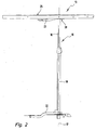
- Figur 2
- eine Seitenansicht des bevorzugten Ausführungsbeispiels des Beschlags ohne Eckschrankperipherie,
- Figur 3
- eine perspektivische Ansicht von unten auf die als Lagerkreuz ausgebildete Trageinrichtung mit dem daran befestigten oberen Tragteil,
- Figur 4
- einen Schnitt durch die Drehlagereinrichtung und einen Teil des oberen Tragteils,
- Figur 5
- eine perspektivische Ansicht der Säule mit oberem Säulenteil und des oberen Tragteils,
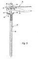
- Figur 6
- einen Schnitt gemäß der
Figur 4 mit zusätzlichem Schnitt durch das obere Säulenteil.
- FIG. 1
- a plan view of a kitchen corner cabinet with the preferred embodiment of the fitting according to the invention,
- FIG. 2
- a side view of the preferred embodiment of the fitting without Eckschrankperipherie,
- FIG. 3
- a perspective view from below of the bearing device formed as a bearing cross with the attached upper support member,
- FIG. 4
- a section through the pivot bearing device and a part of the upper support member,
- FIG. 5
- a perspective view of the column with upper column part and the upper support member,
- FIG. 6
- a section according to the
FIG. 4 with additional cut through the upper pillar part.
Der Eckschrank 11 einer Einbauküche enthält ein Karussell 12, das von einem Eckschrankbeschlag 13, mindestens einem Fachboden 14 und einer Tür 15 gebildet wird, wobei der mindestens eine Fachboden 14 und die Tür 15 vom Eckschrankbeschlag 13 gehalten wird. Vorzugsweise wird die Tür 15 von zwei separaten Türflügeln 15a, 15b gebildet, die beim Öffnen relativ zueinander beweglich sind.The
Der Eckschrankbeschlag 13 weist eine in Gebrauchslage, das heißt im in den Eckschrank 11 eingebauten Zustand vertikal ausgerichtete Säule 16 auf, die oben in nachfolgend näher beschriebener Weise und unten am Schrankboden gelagert wird. In der Regel ist die Säule 16 als zentrale, zu einer Drehachslinie 17 koaxiale Drehsäule ausgebildet. Alternativ ist es möglich, eine U-förmige Säule zu verwenden, die auch als Karussellgestell bezeichnet werden könnte, wobei hier horizontal verlaufende Lagerarme drehbar gelagert sind. Die Säule 16 besitzt ein unteres Säulenteil 18 und ein teleskopartig mit dem unteren Säulenteil 18 zusammengestecktes oberes Säulenteil 19, wobei die beiden Säulenteile 18, 19 voneinander verschiedene Durchmesser aufweisen. Vorzugsweise besitzt das obere Säulenteil 19 gegenüber dem unteren Säulenteil 18 einen kleineren Durchmesser.The Eckschrankbeschlag 13 has a in-use position, that is in the built-in
Der Eckschrank 12 weist ferner eine über Eck gehende Schranköffnung 20 auf, der eine von den beiden bereits erwähnten Türflügeln 15a, 15b gebildete, insofern zweiflüglige Tür zugeordnet ist. Die beiden Türflügel 15a, 15b stehen in der Schließstellung, wenn sie die Schranköffnung 20 verschließen, etwa rechtwinkelig zueinander. Dabei bildet jeder Flügel 15a, 15b der benachbarten Seitenwand 21a, 21b einen rechten Winkel, wobei der eine Türflügel 15a die Stirnseite der einen Seitenwand 21a und der andere Türflügel 15b die Stirnseite der anderen Seitenwand 21b übergreift. Bei einer Alternative kann auch eine Tür vorgesehen sein, deren Türflügel in winkelstabiler Stellung zueinander ausgerichtet sind und in dieser Stellung zum Öffnen der Tür radial nach innen gedrückt werden. Bei einer weiteren Alternative kann auch eine Tür vorgesehen sein, die aus einem einzelnen Türelement besteht, das sich quer über die Schranköffnung, diese in Schließstellung verschließend, erstreckt. Zum Öffnen wird das Türelement dann radial nach innen gedrückt.The
Der wenigstens eine Fachboden 14 erstreckt sich nicht über einen vollen Kreisumfang. Er weist vielmehr einen zweckmäßigerweise über einen kleineren Winkel als 90° gehenden sektorenförmigen Ausschnitt auf, der bei den beiden Türflügeln 15a, 15b angeordnet ist. Das von den beiden Türflügeln 15a, 15b gebildet Türeck ragt in diesen Ausschnitt hinein.The at least one
Um das Schrankinnere zugängig zu machen, werden die beiden Türflügel 15a, 15b zum Öffnen nach innen in die Offenstellung gedrückt. Hierbei führen die beiden voneinander getrennten Türflügel 15a, 15b einen mit Bezug auf die Winkelhalbierende 50 des Türecks spiegelbildliche Bewegung aus, die sich aus einer den Winkel zwischen den beiden Türflügeln 15a, 15b verkleinernden Einklappbewegung und einer diese überlagernde Einfahrbewegung entlang der Winkelhalbierenden 50 zusammensetzt. Bei dieser Bewegung gelangen die Türflügel 15a, 15b weiter in den Ausschnitt, der zumindest soweit es für das Eintauchen der Türflügel 15a, 15b benötigt wird, auch von sonstigen Teilen frei ist. Aufgrund dieser Einklappbewegung mit überlagerter Einfahrbewegung kommen die beiden Türflügel 15a, 15b von den Seitenwänden 21a, 21b des Eckschranks 11 frei. Dabei gelangen die Türflügel 15a, 15b nach innen und werden gegebenenfalls gleichzeitig abgesenkt, so dass sich das Karussell 12 im Eckschrank 11 drehen lässt ohne dass die Türflügel 15a, 15b an den Seitenwänden 21a, 21b streifen.In order to make the inside of the cabinet accessible, the two
Auf diese Weise kann jede Stelle des wenigstens einen Fachbodens 14 nach vorne zur Schranköffnung 20 gedreht werden, so dass überall Gegenstände eingestellt oder entnommen werden können.In this way, each point of the at least one
Beim Schließen der Tür 15 laufen umgekehrte Bewegungen. Gelangt das Karussell 12 nach einem Verdrehen wieder in die Drehstellung, in der sich die beiden Türflügel 15a, 15b an der Schranköffnung 20 befinden, können sich die Türflügel 15a, 15b nach außen in die Schließstellung bewegen. Hierbei handelt es sich um eine den Winkel zwischen den Türflügeln 15a, 15b vergrößerte Ausklappbewegung mit überlagerter Ausfahrbewegung in Richtung der Winkelhalbierenden 50, gegebenenfalls bei gleichzeitiger Aufwärtsbewegung der beiden Türflügel 15a, 15b.When closing the
Der Eckschrankbeschlag weist ferner ein unteres und ein oberen Tragteil 22, 23 auf, wobei das untere Tragteil 22 am unteren Säulenteil 18 befestigt ist. An der Unterseite des unteren Tragteils 22 ist eine Steuergestänge angeordnet, mit dem die Türflügelbewegung beim Öffnen und Schließen gesteuert wird. Bezüglich weiterer Details des Steuergestänges wird insbesondere auf die
Zum Eckschrank 11 gehört ferner noch eine beispielsweise von einer Arbeitsplatte gebildete obere Schrankabdeckung 24, an die unterseitig eine Trageinrichtung in Form eines Lagerkreuzes 25 montiert ist. Das Lagerkreuz 25 besitzt mehrere Lagerarme 26 die mit den Seitenwänden 21a, 21b bzw. mit einer Eckschrankrückwand verbunden sind.For
Das obere Tragteil 23 ist drehbar an einer mit der oberen Schrankabdeckung 24 verbundenen Drehlagereinrichtung 28 gelagert.The
Wie insbesondere in den
Wie insbesondere in den
Wie insbesondere in den
Es ist eine Steckeinrichtung 38 zum Zusammenstecken von oberem Säulenteil 19 und oberem Tragteil 23 vorgesehen, die außermittig der Drehachslinie 17 angeordnete Steckzapfen 39 aufweist, denen korrespondierende Stecklöcher 40 zugeordnet sind. Die Längsachsen 45 der Steckzapfen 39 erstrecken sich im Wesentlichen parallel zur Drehachslinie. Die Steckzapfen 39 sitzen an einer am oberen Ende des oberen Säulenteils 19 insbesondere einstückig mit diesem verbundenen Andockplatte 41. Beispielsweise sind drei insbesondere in gleichem Abstand voneinander an der Andockplatte 41 sitzende Steckzapfen 39 vorgesehen. Korrespondierend dazu befinden sich am oberen Tragteil 23 die Stecklöcher 40, beispielsweise auch drei an der Zahl. Ein jeweiliger Steckzapfen 39 kann widerhakenartig ausgebildet sein, mit einem mittigen Schlitz, so dass der Steckzapfen 39 beim Durchstecken durch das zugeordnete Steckloch 40 zusammengepresst wird. Nach dem Durchstecken schnappt der Steckzapfen 39 wieder auf, so dass er entgegen der Einsteckrichtung axial am oberen Tragteil 23 fixiert ist. Oberes Tragteil 23 und oberes Säulenteil 19 sind somit drehfest miteinander verbunden. Gegebenenfalls ist es möglich, das zwischen dem oberen Tragteil 23 und dem oberen Säulenteil 19 bezüglich der Drehachslinie 17 axiales Spiel vorhanden ist, beispielsweise dadurch das der Hals der Steckzapfen 39 länger ist als die Länge der Stecklöcher 40.It is a plug-in
Claims (15)
- Mounting for a corner cupboard (11), in particular a kitchen corner cupboard, with a column (16) rotatable around a rotation axis line (17) and having a lower column section (18) and an upper column section (19) which is connected telescopically to the lower column section (18), and with an upper and lower support section (22, 23) for a door (15), wherein the two support sections (22, 23) together with the column (16) form in the mounted state a rotating unit, characterised in that the upper support section (23) may be or is mounted rotatably on a rotary bearing device (28) connected or connectable to an upper cupboard cover (24), and that the upper column section (19) may be connected releasably to the upper support section (23), so that the column (16) in the mounted state is supported rotatably on the rotary bearing device (28) via the upper support section (23).
- Mounting according to claim 1, characterised in that the upper support section (23) rests on a bearing element connected to a support fixture (25) to be fitted immovably in the corner cupboard (11).
- Mounting according to claim 2, characterised in that the bearing element is formed by a bearing pin (31) on which the upper support section (23) rests.
- Mounting according to claim 2 or 3, characterised in that the bearing pin (31) is fitted non-rotatably to the support fixture (25) and the upper support section (23) is mounted rotatably on the bearing pin (31).
- Mounting according to any of the preceding claims, characterised in that the upper column section (19) is connected non-rotatably to the upper support section (23) via coupling means.
- Mounting according to claim 5, characterised in that the coupling means provided are a plug-in device (38) for plugging together or a screw device for screwing together the upper column section (19) and the upper support section (23).
- Mounting according to claim 6, characterised in that the plug-in device (38) has plug-in pins (39) located off-centre of the rotation axis line (17) for the non-rotatable connection of the column section (19) and the upper support section (23), to which corresponding insertion holes (40) are assigned.
- Mounting according to claim 7, characterised in that the plug-in pins (39) are so designed that locking between the upper column section (19) and the upper support section (23) is made possible without tools.
- Mounting according to claim 7 or 8, characterised in that the longitudinal axes (45) of the plug-in pins (39) extend substantially parallel to the rotation axis line (17).
- Mounting according to any of claims 7 to 9, characterised in that the plug-in pins (39) are located on the upper column section (19) and the insertion holes (40) on the upper support section (23).
- Mounting according to any of the preceding claims, characterised in that a locking device (36) is provided for axial securing of the upper support section (23) to the bearing pin (31).
- Mounting according to claim 11, characterised in that the locking device (36) is so designed that a releasable connection is provided between the upper support section (23) and the bearing pin (31).
- Mounting according to claim 12, characterised in that the locking device (36) has at least one retaining ring (37) resting axially immovably on the bearing pin (31).
- Mounting according to claim 11, characterised in that the locking device (36) is so designed that a non-releasable connection, in particular a riveted connection to be made by riveting around a slip-on section (34) of the bearing pin (31), is provided between the upper support section (23) and the bearing pin (31).
- Mounting according to any of claims 2 to 14 characterised in that, in the mounted state, there is axial play between the upper support section (23) and the support fixture (25) and/or between the upper support section (23) and the upper column section (19).
Applications Claiming Priority (1)
| Application Number | Priority Date | Filing Date | Title |
|---|---|---|---|
| DE102006042710A DE102006042710A1 (en) | 2006-09-12 | 2006-09-12 | Hardware for a corner cabinet |
Publications (2)
| Publication Number | Publication Date |
|---|---|
| EP1900304A1 EP1900304A1 (en) | 2008-03-19 |
| EP1900304B1 true EP1900304B1 (en) | 2010-10-13 |
Family
ID=38738947
Family Applications (1)
| Application Number | Title | Priority Date | Filing Date |
|---|---|---|---|
| EP07015137A Active EP1900304B1 (en) | 2006-09-12 | 2007-08-02 | Fitting for a corner cupboard |
Country Status (3)
| Country | Link |
|---|---|
| EP (1) | EP1900304B1 (en) |
| AT (1) | ATE484210T1 (en) |
| DE (2) | DE102006042710A1 (en) |
Family Cites Families (4)
| Publication number | Priority date | Publication date | Assignee | Title |
|---|---|---|---|---|
| DE29823024U1 (en) * | 1998-12-24 | 1999-02-18 | Hettich Hetal Werke | Carousel device for a corner cabinet |
| DE202004008207U1 (en) * | 2004-05-18 | 2005-09-29 | Heinrich J. Kesseböhmer KG | Corner cupboard, especially kitchen corner cupboard |
| DE202005005888U1 (en) * | 2005-04-13 | 2006-08-17 | Heinrich J. Kesseböhmer KG | Corner cupboard, especially kitchen corner cupboard |
| DE202006009070U1 (en) * | 2006-06-09 | 2006-08-17 | Hetal-Werke Franz Hettich Gmbh & Co. Kg | Carrousel for corner cupboards comprises telescopic vertical shaft whose upper section carries mountings, to which shelves are attached |
-
2006
- 2006-09-12 DE DE102006042710A patent/DE102006042710A1/en not_active Ceased
-
2007
- 2007-08-02 DE DE502007005325T patent/DE502007005325D1/en active Active
- 2007-08-02 AT AT07015137T patent/ATE484210T1/en active
- 2007-08-02 EP EP07015137A patent/EP1900304B1/en active Active
Also Published As
| Publication number | Publication date |
|---|---|
| EP1900304A1 (en) | 2008-03-19 |
| ATE484210T1 (en) | 2010-10-15 |
| DE102006042710A1 (en) | 2008-03-27 |
| DE502007005325D1 (en) | 2010-11-25 |
Similar Documents
| Publication | Publication Date | Title |
|---|---|---|
| EP2713816B1 (en) | Fitting for corner cabinets | |
| DE19543601A1 (en) | Swivelling support on top of very large umbrella | |
| EP3087866B1 (en) | Fitting for a corner cupboard and corner cupboard with fitting | |
| EP2353438A2 (en) | Fitting for corner cupboards | |
| EP3315047B1 (en) | Guide device for controlling the movement of a door of a corner cupboard | |
| EP2064971A1 (en) | Fitting for a corner cupboard | |
| DE10025338B4 (en) | folding table | |
| EP1988242B1 (en) | Flap holder for a cabinet flap | |
| EP1835107B1 (en) | Flap holder for a cabinet flap | |
| DE3808327A1 (en) | Pivot-arm device | |
| EP1900304B1 (en) | Fitting for a corner cupboard | |
| DE10136218B4 (en) | Toilet seat for the disabled | |
| EP1505238B1 (en) | Hinge for the pivotal connection of two elements of a folding door | |
| DE102014101245B3 (en) | Support arm with multi-purpose lock | |
| DE202018101922U1 (en) | Automatically detachable mechanical angle adjustment device | |
| DE19860241B4 (en) | Carousel device for holding at least one shelf in a corner cabinet and a double-leaf door | |
| EP2168453A1 (en) | Device and method for assembling a pull-out guide for pull-out elements | |
| DE202006009070U1 (en) | Carrousel for corner cupboards comprises telescopic vertical shaft whose upper section carries mountings, to which shelves are attached | |
| EP0702914A1 (en) | Furniture drawer element, for drawers or the like | |
| EP1817979B1 (en) | Fitting for a corner cupboard, in particular a kitchen corner cupboard | |
| DE10141555A1 (en) | table | |
| EP2287427B1 (en) | Single-axis hinge | |
| DE102013010090B4 (en) | Carabiner hook | |
| DE102005049392B4 (en) | Storage device for a cabinet and shelf for this | |
| DE2949019C2 (en) | Transportable sales trailer |
Legal Events
| Date | Code | Title | Description |
|---|---|---|---|
| PUAI | Public reference made under article 153(3) epc to a published international application that has entered the european phase |
Free format text: ORIGINAL CODE: 0009012 |
|
| AK | Designated contracting states |
Kind code of ref document: A1 Designated state(s): AT BE BG CH CY CZ DE DK EE ES FI FR GB GR HU IE IS IT LI LT LU LV MC MT NL PL PT RO SE SI SK TR |
|
| AX | Request for extension of the european patent |
Extension state: AL BA HR MK YU |
|
| 17P | Request for examination filed |
Effective date: 20080328 |
|
| 17Q | First examination report despatched |
Effective date: 20080509 |
|
| AKX | Designation fees paid |
Designated state(s): AT CH DE FR IT LI |
|
| GRAP | Despatch of communication of intention to grant a patent |
Free format text: ORIGINAL CODE: EPIDOSNIGR1 |
|
| GRAS | Grant fee paid |
Free format text: ORIGINAL CODE: EPIDOSNIGR3 |
|
| GRAA | (expected) grant |
Free format text: ORIGINAL CODE: 0009210 |
|
| AK | Designated contracting states |
Kind code of ref document: B1 Designated state(s): AT CH DE FR IT LI |
|
| REG | Reference to a national code |
Ref country code: CH Ref legal event code: NV Representative=s name: TROESCH SCHEIDEGGER WERNER AG Ref country code: CH Ref legal event code: EP |
|
| REF | Corresponds to: |
Ref document number: 502007005325 Country of ref document: DE Date of ref document: 20101125 Kind code of ref document: P |
|
| PLBI | Opposition filed |
Free format text: ORIGINAL CODE: 0009260 |
|
| 26 | Opposition filed |
Opponent name: KESSEBOEHMER BESCHLAGSYSTEME GMBH & CO. KG Effective date: 20110506 |
|
| REG | Reference to a national code |
Ref country code: DE Ref legal event code: R026 Ref document number: 502007005325 Country of ref document: DE Effective date: 20110506 |
|
| PLAX | Notice of opposition and request to file observation + time limit sent |
Free format text: ORIGINAL CODE: EPIDOSNOBS2 |
|
| PLAF | Information modified related to communication of a notice of opposition and request to file observations + time limit |
Free format text: ORIGINAL CODE: EPIDOSCOBS2 |
|
| PLBB | Reply of patent proprietor to notice(s) of opposition received |
Free format text: ORIGINAL CODE: EPIDOSNOBS3 |
|
| PLCK | Communication despatched that opposition was rejected |
Free format text: ORIGINAL CODE: EPIDOSNREJ1 |
|
| APBM | Appeal reference recorded |
Free format text: ORIGINAL CODE: EPIDOSNREFNO |
|
| APBP | Date of receipt of notice of appeal recorded |
Free format text: ORIGINAL CODE: EPIDOSNNOA2O |
|
| APAH | Appeal reference modified |
Free format text: ORIGINAL CODE: EPIDOSCREFNO |
|
| APBQ | Date of receipt of statement of grounds of appeal recorded |
Free format text: ORIGINAL CODE: EPIDOSNNOA3O |
|
| APAH | Appeal reference modified |
Free format text: ORIGINAL CODE: EPIDOSCREFNO |
|
| APAH | Appeal reference modified |
Free format text: ORIGINAL CODE: EPIDOSCREFNO |
|
| REG | Reference to a national code |
Ref country code: FR Ref legal event code: PLFP Year of fee payment: 10 |
|
| REG | Reference to a national code |
Ref country code: FR Ref legal event code: PLFP Year of fee payment: 11 |
|
| APBU | Appeal procedure closed |
Free format text: ORIGINAL CODE: EPIDOSNNOA9O |
|
| REG | Reference to a national code |
Ref country code: DE Ref legal event code: R100 Ref document number: 502007005325 Country of ref document: DE |
|
| PLBN | Opposition rejected |
Free format text: ORIGINAL CODE: 0009273 |
|
| STAA | Information on the status of an ep patent application or granted ep patent |
Free format text: STATUS: OPPOSITION REJECTED |
|
| 27O | Opposition rejected |
Effective date: 20170901 |
|
| REG | Reference to a national code |
Ref country code: DE Ref legal event code: R082 Ref document number: 502007005325 Country of ref document: DE Representative=s name: REHBERG HUEPPE + PARTNER PATENTANWAELTE PARTG , DE |
|
| REG | Reference to a national code |
Ref country code: FR Ref legal event code: PLFP Year of fee payment: 12 |
|
| P01 | Opt-out of the competence of the unified patent court (upc) registered |
Effective date: 20230528 |
|
| PGFP | Annual fee paid to national office [announced via postgrant information from national office to epo] |
Ref country code: IT Payment date: 20230831 Year of fee payment: 17 Ref country code: CH Payment date: 20230902 Year of fee payment: 17 Ref country code: AT Payment date: 20230818 Year of fee payment: 17 |
|
| PGFP | Annual fee paid to national office [announced via postgrant information from national office to epo] |
Ref country code: FR Payment date: 20230821 Year of fee payment: 17 Ref country code: DE Payment date: 20230821 Year of fee payment: 17 |