EP1900151B1 - System comprising at least a master unit and a plurality of slave units - Google Patents
System comprising at least a master unit and a plurality of slave units Download PDFInfo
- Publication number
- EP1900151B1 EP1900151B1 EP05756136A EP05756136A EP1900151B1 EP 1900151 B1 EP1900151 B1 EP 1900151B1 EP 05756136 A EP05756136 A EP 05756136A EP 05756136 A EP05756136 A EP 05756136A EP 1900151 B1 EP1900151 B1 EP 1900151B1
- Authority
- EP
- European Patent Office
- Prior art keywords
- master unit
- slave units
- sectors
- units
- room
- Prior art date
- Legal status (The legal status is an assumption and is not a legal conclusion. Google has not performed a legal analysis and makes no representation as to the accuracy of the status listed.)
- Expired - Lifetime
Links
Images


Classifications
-
- H—ELECTRICITY
- H04—ELECTRIC COMMUNICATION TECHNIQUE
- H04L—TRANSMISSION OF DIGITAL INFORMATION, e.g. TELEGRAPHIC COMMUNICATION
- H04L41/00—Arrangements for maintenance, administration or management of data switching networks, e.g. of packet switching networks
- H04L41/08—Configuration management of networks or network elements
- H04L41/0803—Configuration setting
-
- H—ELECTRICITY
- H04—ELECTRIC COMMUNICATION TECHNIQUE
- H04L—TRANSMISSION OF DIGITAL INFORMATION, e.g. TELEGRAPHIC COMMUNICATION
- H04L12/00—Data switching networks
- H04L12/28—Data switching networks characterised by path configuration, e.g. LAN [Local Area Networks] or WAN [Wide Area Networks]
- H04L12/2803—Home automation networks
- H04L12/2816—Controlling appliance services of a home automation network by calling their functionalities
- H04L12/282—Controlling appliance services of a home automation network by calling their functionalities based on user interaction within the home
-
- H—ELECTRICITY
- H04—ELECTRIC COMMUNICATION TECHNIQUE
- H04L—TRANSMISSION OF DIGITAL INFORMATION, e.g. TELEGRAPHIC COMMUNICATION
- H04L61/00—Network arrangements, protocols or services for addressing or naming
-
- H—ELECTRICITY
- H04—ELECTRIC COMMUNICATION TECHNIQUE
- H04L—TRANSMISSION OF DIGITAL INFORMATION, e.g. TELEGRAPHIC COMMUNICATION
- H04L61/00—Network arrangements, protocols or services for addressing or naming
- H04L61/30—Managing network names, e.g. use of aliases or nicknames
-
- H—ELECTRICITY
- H04—ELECTRIC COMMUNICATION TECHNIQUE
- H04W—WIRELESS COMMUNICATION NETWORKS
- H04W8/00—Network data management
- H04W8/26—Network addressing or numbering for mobility support
-
- H—ELECTRICITY
- H04—ELECTRIC COMMUNICATION TECHNIQUE
- H04L—TRANSMISSION OF DIGITAL INFORMATION, e.g. TELEGRAPHIC COMMUNICATION
- H04L12/00—Data switching networks
- H04L12/28—Data switching networks characterised by path configuration, e.g. LAN [Local Area Networks] or WAN [Wide Area Networks]
- H04L12/2803—Home automation networks
- H04L2012/284—Home automation networks characterised by the type of medium used
- H04L2012/2841—Wireless
-
- H—ELECTRICITY
- H04—ELECTRIC COMMUNICATION TECHNIQUE
- H04L—TRANSMISSION OF DIGITAL INFORMATION, e.g. TELEGRAPHIC COMMUNICATION
- H04L41/00—Arrangements for maintenance, administration or management of data switching networks, e.g. of packet switching networks
- H04L41/08—Configuration management of networks or network elements
- H04L41/0893—Assignment of logical groups to network elements
-
- H—ELECTRICITY
- H04—ELECTRIC COMMUNICATION TECHNIQUE
- H04W—WIRELESS COMMUNICATION NETWORKS
- H04W84/00—Network topologies
- H04W84/18—Self-organising networks, e.g. ad-hoc networks or sensor networks
- H04W84/20—Leader-follower arrangements
Definitions
- the invention relates to a system comprising at least one master unit and a plurality of slave units, said master unit and at least one of said slave units comprising means for performing preferably two-way communication via radio frequency channels, wherein said at least one master unit comprises means for transmitting control signals to said slave units, said slave units each being provided with a unique address and each being associated with a controllable device.
- control systems of the of the above-mentioned type it is usually a time-consuming and confusing job for the user to perform a set-up of a system wherein a remote control is used for operating a plurality of devices.
- the invention relates to a system as specified in claim 1 comprising at least one master unit and a plurality of slave units, said master unit and at least one of said slave units comprising means for performing communication via radio frequency channels, wherein said at least one master unit comprises means for transmitting control signals to said slave units, said slave units each being provided with a unique address and each being associated with a controllable device, and wherein said at least one master unit comprises means for configuring said slave units addressable by said master unit in a number of sectors, wherein said master unit further has means for allocating predefined identifications to said slave units, and wherein said master unit has display means, by means of which said predefined identifications may be displayed.
- the system may be configured by the user in a manner allowing operations to be performed in a user-friendly manner, while also giving the user ample information and overview of the possibilities presented by the system/master unit as regards operation of the devices associated with the slave units.
- said master unit may be designed for performing an auto-configuration, by means of which communication with said slave units is established sequentially, addresses and properties are stored and arranged in a predefined manner by said master unit.
- slave units that are accessible by the master unit may automatically be contacted by the master unit and addresses, properties etc. may automatically be registered in a storage facility of the master unit.
- the properties, that may be registered may for example be the type of the device associated with each slave unit, e.g. a window operator/opener, a Venetian blind, a roller curtain, a shutter, etc.
- said predefined manner, in which said slave units may be automatically arranged may comprise a arrangement in consideration of the property of the device associated with the slave unit, in such a manner that slave units having similar properties are arranged in a consecutive manner, e.g. with a unique identification comprising a label and a number.
- all slave units are automatically arranged in a logic manner, e.g. all window operators listed with a label such as “Window” or “Window operator” and with a number, e.g. the numbers 1 - n, by means of which the user may address the individual operators.
- said master unit may be configured for facilitating a naming and/or re-naming of slave units and/or sectors such as for example groups, rooms, zones etc.
- said master unit may be configured for establishing a group comprising all slave units of a of a specific type when at least two slave units of said specific type have been registered in a sector.
- a group comprising these devices are created under e.g. the label of "All Window Operators.
- the user will automatically be presented with the option of being able to e.g. close all windows with one simple keypad operation.
- the facility of establishing such "All"-groups are dynamic, e.g. if for example the units with the label "Window Operator” are divided into two groups, such an "all' group will be established for each of these, if at least two window operators are placed in such a group.
- a group comprising devices that are dissimilar for example a group comprising e.g. blinds and roller shutters, which may then be operated simultaneously, for example in order to shield from the sunlight.
- said sectors may be associated with a locality, e.g. a room or part of a room in a house, an apartment etc., and slave units located at said locality may be arranged in said sectors.
- a locality e.g. a room or part of a room in a house, an apartment etc.
- slave units located at said locality may be arranged in said sectors.
- the system may be arranged in accordance with the specific needs of the user and in accordance with the specific premises and locations.
- At least one of said sectors may be associated with a room, i.e. one or more slave units of any type located in said room.
- At least one of said sectors may be associated with a room and may consist of at least two slave units of one or more specific types.
- At least one of said sectors may be associated with a plurality of rooms and may comprise at least two slave units of one or more specific types.
- said control signal transmitted to at least one of said slave units may in addition to an address comprise information related to the type of operation, e.g. open/close, increase/decrease, information related to a ratio, e.g. 60%, or a predefined level, presetting or the like.
- said master unit may comprise timing means for facilitating delayed or real-time execution of said transmission of control signals.
- a time-dependent execution of operations may be performed, e.g. the sequential transmission of control signals may comprise a control signal transmitted to e.g. a window operator 30 minutes after activation of the function control key in order to achieve that the window is opened for example 25 %, and after yet e.g. 10 minutes a subsequent control is transmitted ordering the window operator to close the window fully.
- a timing function may be based on a real-time function or may be based on a facility measuring lapsed time only.
- said master control may be designed in order to transmit an additional control signal, requesting a status report from the slave unit in question, and wherein the slave unit may calculate a transmission time for said additional control signal in consideration of said information related to a ratio.
- the system may be designed in a cost-efficient and effective manner, e.g. with relatively limited resources as regards computational power, communication activity etc., since the system will not be burdened with control and request signals sent with very small time intervals. Instead, a control signal requesting a status, e.g. in Order to conform that the requested action has taken place, will be transmitted normally only once and at a time when it is expected that the required action has been fully executed.
- the slave unit will have calculated or estimated the time that the slave unit will need to perform the requested operation, e.g open to 80%, and this Information is transmitted to the master unit, for example with the acknowledgement signal.
- the required power for operating the system is also reduced, thus also optimizing the battery requirements for e.g. the master unit
- the activity on the channels available for the communication will also be reduced to a minium, thus allowing other units to communicate efficiently.
- said slave units may be configured for providing feedback to the master unit upon completion of an operation, e.g. operation succeeded or failed, the status of the device, e.g. 40% open etc.
- this facility may serve also, for providing status information regarding the respective devices, e.g. in case the user wants to make sure that all windows have been closed before going to bed or that all doors are locked.
- said feedback may be limited to feedback relating to non-executed operations.
- the user is provided with the information that is highly relevant for the user. For example, in case a group of blinds have been commanded to close 100%, it would not serve the interest of the user to receive one brief message after the other concerning the specific blinds. Instead, if one or more operations fail, a message is provided to the user informing him/her that e.g. two blinds have failed.
- the user may select these two blinds and be informed that e.g. the first has not been fully closed and that contact has not been established with the other one.
- said master unit may be configured for performing a data transfer to a similar additional master unit, said data transfer in addition to addresses of slave units includes labels configuration of the slave units in sectors, e.g. groups, rooms and zones, and other user-defined settings.
- said master unit may be configured, for facilitating an editing of the configuration of the slave units in sectors, e.g. groups, rooms and zones, and other user-defined settings.
- said master unit may be configured for operating in a predestined mode, wherein slave units and/or sectors, e.g. groups, relating to a specific locality, e.g. room, may be selected for operation.
- said master unit may be configured for operating slave units and/or sectors, e.g. groups, relating to other localities also, e.g. rooms, but that the master units returns automatically to the predestined units and/or sectors.
- slave units and/or sectors e.g. groups, relating to other localities also, e.g. rooms, but that the master units returns automatically to the predestined units and/or sectors.
- the master unit will be universally useable, but that it will automatically return to the mode, wherein the user may readily find and operate the units, groups, etc. relating to the specific room.
- said master unit may be configured for operating only slave units and/or sectors, e.g. groups relating to a specific locality, e.g. room, in said predestined mode.
- slave units and/or sectors e.g. groups relating to a specific locality, e.g. room, in said predestined mode.
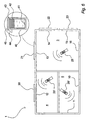
- FIG. 1 An example of a control system according to an embodiment of the invention, e.g. a home automation system or part thereof, is illustrated in fig. 1 .
- a building, a house, an apartment or the like 1 is illustrated in a schematic manner, wherein a number of devices, e.g. equipment and fittings, which are controlled by a system in accordance with the invention, are furthermore illustrated in a general manner.
- the house or apartment 1 may comprise a number of rooms, for example the rooms 3, 4 and 5, and in these rooms a number of windows 10, 11, 12, 13, 14, 15 and 16 may be located. Further, some of these windows may be provided with awnings 20, 21, 22 and 23 as also illustrated. It will be understood that these pieces of equipment are only examples of devices that may be controlled by means of the system, e.g. by means of one or more remote controls 25. Such remote controls are also referred to as master units in the following.
- a window 40 may as shown in fig. 1a comprise e.g. a window actuator, operator or opener 41, a Venetian blind 42 that may be operated by drive means 43 and an awning 44 placed outside the window and operated by drive means 45.
- slave units e.g. means for receiving control signals from the remote control(s) 25 and for operating in accordance with received signals.
- Such means may comprise radio frequency receiving and transmitting means, although it will be understood that some devices may be connected by e.g. a wire bus that may serve to transmit signals from a common RF receiver to the respective slave units associated with the respective devices etc.
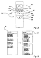
- FIG. 2 An example of a remote control or master unit 25 is shown in further detail in fig. 2 .
- This remote control comprises RF receiving and transmitting means, a power source such as a battery, storing means, control means etc., and further as shown in fig. 2 , the remote control comprises operating means in the form of a display 26, an operating keypad 27 for e.g. displaying information on the display 26, for selecting options, devices etc. and control keys 28 for e.g. operating a selected device.
- an initial set-up or configuration must be performed, whereby an automatic registration of the devices is performed.
- This is initiated by means of the remote control 25, e.g. by inserting batteries in the remote control 25, where after the user is instructed to switch on the mains power to the devices and operate a key, corresponding to e.g. a "Ready"-symbol on the display, on the keypad 27 in order to indicate to the remote control, that an auto set-up may be executed.
- a unique code in the remote control is transmitted to all remote-controlled devices, e.g. slave units that are in proximity of the remote control 25 communication-wise.
- the slave units will during this procedure transmit a response signal to the remote control 25, containing information in the form of an address and the type of the slave unit, e.g. a window operator, an awning, blinds etc.
- the exchange of addresses and of the code may take place by the exchange of an address and of the code being completed between one slave unit and the master unit/remote control 25 before carrying out the exchange between the following slave units and the remote control and this initiation process may continue sequentially until the last of the slave units has transmitted its address and type and has received the Code.
- the sequence of configuration of the respective units may be determined in various ways and may e.g. be determined by the units being susceptible to the initiation signal at different time intervals which may be mutually independent and potentially randomly divided between the units. The unit with which the susceptible time interval and an initiation signal first coincide will thus be configured first etc.
- the system When the auto configuration has been completed, e.g. signalled by an icon for auto set-up on the display 26 and a message on the display 26, the system is ready for operation.
- the remote control 25 has now stored a list of devices including the address for each and the type, e.g. window operator, blind, awning light etc.
- the master unit is configured for arranging the slave units or devices, which have now been associated with the master unit, in such a manner that the slave units are shown in a list on the display 26 assembled in accordance with the type of equipment and with a numbering, e.g. showing first window operator no. 1-7, blind no. 1-5, awning no. 1-4 etc.
- the user may scroll up and down this list, e.g. using the navigation keys 27a and 27b, until a device is found and selected, in which case the device may be operated by means of the keys 28a, 28b and 28c.
- the master unit 25 facilitates a division into e.g. groups of the available controllable units, which will be further explained in the following.
- the display means 26 of the master unit will involve only two levels, i.e. "House", which, when selected, will be replaced by the list of all units, or, if a "Find” command is used, the desired type can be found before going into the number-level.
- "House" which, when selected, will be replaced by the list of all units, or, if a "Find” command is used, the desired type can be found before going into the number-level.
- the box 30 represents this arrangement of the available units.
- the master unit has automatically created a "All"-group, for example "All window operators”.
- a room may be defined, for example the room 3 in fig. 1 .
- the individual units may thus be selected and allocated to the room, i.e. by pressing the key 27c to enter the unit in the "room".
- the control keys 28 it is possible to observe which unit has been selected by pressing the control keys 28 for a brief period of time. Further units can be selected and added to the "room” as described, until the "room” is finally stored as e.g. "Room 1 ". This is illustrated in fig. 3 with the box 31.
- the master unit When a room has been created, the master unit will offer to save all remaining units in a room, e.g. "Room 2" as show in fig. 3 , or, if this is refused, the display will return to the list from which remaining products/units can be selected for a new room, etc. It is noted that when units has been selected for a room and the room is stored, the units are automatically renumbered as also indicated in fig. 3 .
- a "Room” may comprise the controllable units in a specific room, for example the room 3 in fig. 1 .
- the window operators 13 - 16 are selected, the awnings 21 - 23 and, if other types of equipment are provided, for example blinds, roller shutters, light etc, these may be included as well.
- the master unit may now involve one more level.
- "House” it will according to this embodiment be possible to choose between e.g. "Room 1" and "Room 2" as illustrated with the box 31 in fig. 3 .
- a listing as shown at 30 will be available to the user, comprising four windows, three awnings, two lights and further three "all"-groups.
- the user now creates a room, "room 1", as shown at 31 comprising three windows and one awning. As mentioned above, an "all” group is also automatically created when the room is stored. Further, the remaining devices are assigned to a “room” as shown at 32. Now, when the user wants to operate the devises, the user may select "room”, in which case he/she will be able to select one of the two rooms and subsequently the devices and group(s) comprised in the room.
- the user instead to choose the "house” as indicated at 33, comprising the "all"-groups for selection of the group or subsequently the individual items, in which case the user will be presented with the option of selecting a particular type of device and a specific one of these devices etc.
- a zone may be defined as a group that is created across the already defined rooms.
- a zone 35 will be created, e.g. "zone 1", which comprises a group, "group 1” consisting of the two windows.
- zone 1 may be renamed, for example into “south zone”, whereby the windows in "group 1" will be identified as the windows placed in this zone.
- a group consisting of a number of units of the similar or dissimilar type in a specific room for example a group 50 consisting of the awnings 22 and 23 in the room 3 or a group 51 consisting of the window operators for the windows 10 and 11 in the room 5.
- zones may comprise units of the same type or of different types, but located in different "rooms", or rather the groups defined in such a zone will comprise devices located in different "rooms".
- This is illustrated in fig. 5 with the zone 52 consisting for example of the awning 20 located in the room 4 and the awning 21 in the room 3.
- zones may not only cover different rooms in the same level, but also rooms at different levels, for example in a house having a ground floor and a first floor, e.g. an attic.
- the master unit is designed for facilitating an editing of the programming, renaming etc. that the user has performed. Thereby, it is achieved that in case a mistake has been made during the creation of e.g. a "room", it will not be necessary to start from the beginning again. Further, the addition of newly installed devices is also facilitated hereby.
- the master unit can be configured for performing a data transfer to a similar additional master unit, whereby data such as addresses of slave units, labels, names, configuration of the slave units in sectors, e.g. groups, rooms and zones, and other user-defined settings are transferred to another master unit or remote control 25.
- data such as addresses of slave units, labels, names, configuration of the slave units in sectors, e.g. groups, rooms and zones, and other user-defined settings are transferred to another master unit or remote control 25.
- the user is spared the effort of repeating the necessary operating steps. Further, it is ensured that the contents of the master units matches each other.
- the slave units may provide feedback to the master unit when an operation is completed.
- a feedback may be e.g. operation succeeded or failed, the status of the device, e.g. 40% open etc.
- this facility may serve also for providing status information regarding the respective devices, e.g. in case the user wants to make sure that all windows have been closed before going to bed or that all doors are locked.
- the feedback may preferably be limited to feedback relating to non-executed operations.
- a group of blinds have been commanded to close 100%, it would not serve the interest of the user to receive one brief message after the other concerning the specific blinds.
- a message is provided to the user informing him/her that e.g. two blinds have failed.
- the user may select these two blinds and be informed that e.g. the first has not been fully closed and that contact has not been established with the other one.
- the master unit is provided with a display 26 and means for using icons, pictures, pictograms, graphic illustrations etc, instead of or in addition to text messages in order to enhance the user-friendliness and increase the intelligibility.
- the system may comprise a plurality of master units, e.g. 25, 25' and 25" as shown in fig. 6 .
- master units e.g. 25, 25' and 25" as shown in fig. 6 .
- These may all be similar as regards the registered addresses of slave units including names, configuration of the slave units in sectors, e.g. groups, rooms and zones, and other user-defined settings, since it is possible, as already explained, to perform a data transfer from one master unit to another. If the user has such a number of master units, the user will obviously place one in each room, at least in "major" rooms, where the master unit is needed mostly.
- each master unit 25 will be ready for selecting units or groups located in room 3 (e.g. the display will show e.g. "Room 3")
- the master unit 25' will be ready for selecting units or groups located in room 4
- the master unit 25' will be ready for selecting units or groups located in room 5.
- the master units may be configured in such a manner that it will only be possible to operate units, groups, etc. that are placed in or related to said room with the respective master units. But they may also be configured in such a manner that they may be used for operating other units, groups, etc.
- the window may be found and operated.
- the master unit here after is left, it will automatically return to the room, to which it is assigned, e.g. after a predetermined time the display will again show e.g. "room 3" or "Bedroom” as the case may be.
- the user will not need to use time to find the correct room, but may immediately select and operate the respective devices, thereby contributing to the user-friendliness and comfort of the user.
Landscapes
- Engineering & Computer Science (AREA)
- Computer Networks & Wireless Communication (AREA)
- Signal Processing (AREA)
- Automation & Control Theory (AREA)
- Databases & Information Systems (AREA)
- Human Computer Interaction (AREA)
- Selective Calling Equipment (AREA)
- Mobile Radio Communication Systems (AREA)
- Operating, Guiding And Securing Of Roll- Type Closing Members (AREA)
- Cash Registers Or Receiving Machines (AREA)
Priority Applications (3)
| Application Number | Priority Date | Filing Date | Title |
|---|---|---|---|
| PL05756136T PL1900151T3 (pl) | 2005-07-04 | 2005-07-04 | System zawierający co najmniej jednostkę główną oraz wiele jednostek podporządkowanych |
| AT08021719T ATE523984T1 (de) | 2005-07-04 | 2005-07-04 | System mit mindestens einer haupteinheit und mehreren slave-einheiten |
| EP08021719A EP2079187B1 (en) | 2005-07-04 | 2005-07-04 | System comprising at least a master unit and a plurality of slave units |
Applications Claiming Priority (1)
| Application Number | Priority Date | Filing Date | Title |
|---|---|---|---|
| PCT/DK2005/000462 WO2007003185A1 (en) | 2005-07-04 | 2005-07-04 | System comprising at least a master unit and a plurality of slave units |
Related Child Applications (1)
| Application Number | Title | Priority Date | Filing Date |
|---|---|---|---|
| EP08021719A Division EP2079187B1 (en) | 2005-07-04 | 2005-07-04 | System comprising at least a master unit and a plurality of slave units |
Publications (2)
| Publication Number | Publication Date |
|---|---|
| EP1900151A1 EP1900151A1 (en) | 2008-03-19 |
| EP1900151B1 true EP1900151B1 (en) | 2008-12-17 |
Family
ID=35929861
Family Applications (2)
| Application Number | Title | Priority Date | Filing Date |
|---|---|---|---|
| EP05756136A Expired - Lifetime EP1900151B1 (en) | 2005-07-04 | 2005-07-04 | System comprising at least a master unit and a plurality of slave units |
| EP08021719A Expired - Lifetime EP2079187B1 (en) | 2005-07-04 | 2005-07-04 | System comprising at least a master unit and a plurality of slave units |
Family Applications After (1)
| Application Number | Title | Priority Date | Filing Date |
|---|---|---|---|
| EP08021719A Expired - Lifetime EP2079187B1 (en) | 2005-07-04 | 2005-07-04 | System comprising at least a master unit and a plurality of slave units |
Country Status (10)
| Country | Link |
|---|---|
| US (1) | US8996643B2 (pl) |
| EP (2) | EP1900151B1 (pl) |
| JP (1) | JP2008545301A (pl) |
| CN (1) | CN101218789A (pl) |
| AT (2) | ATE523984T1 (pl) |
| DE (1) | DE602005011871D1 (pl) |
| DK (1) | DK1900151T3 (pl) |
| EA (1) | EA011175B1 (pl) |
| PL (1) | PL1900151T3 (pl) |
| WO (1) | WO2007003185A1 (pl) |
Families Citing this family (21)
| Publication number | Priority date | Publication date | Assignee | Title |
|---|---|---|---|---|
| JP2008545301A (ja) * | 2005-07-04 | 2008-12-11 | ヴィーケーアール ホールディング エー/エス | 少なくとも1つのマスタユニットと複数のスレーブユニットとを備えたシステム |
| FR2931262B1 (fr) * | 2008-05-15 | 2010-05-28 | Somfy Sas | Procede de commande groupee d'ecrans motorises, automatisme pour la mise en oeuvre de ce procede et installations domotiques comprenant un tel automatisme |
| JP2010219643A (ja) * | 2009-03-13 | 2010-09-30 | Sony Corp | リモートコントローラおよびリモートコントロールシステム |
| FR2956224B1 (fr) | 2010-02-09 | 2012-11-02 | Somfy Sas | Procede de fonctionnement d'un dispositif de commande d'equipements domotiques |
| DK2558133T3 (da) | 2010-03-26 | 2020-04-06 | Tepha Inc | Coatinger til fremstillingen og anvendelse af polyhydroxyalkanoat-lægemiddelindretninger |
| US8339085B2 (en) * | 2010-08-30 | 2012-12-25 | Crestron Electronics Inc. | Method for synchronizing a plurality of roller shades using variable linear velocities |
| US8339086B2 (en) * | 2010-08-30 | 2012-12-25 | Crestron Electronics Inc. | System for syncronizing a plurality of roller shades using variable linear velocities |
| KR101958902B1 (ko) * | 2011-09-30 | 2019-07-03 | 삼성전자주식회사 | 전자기기들의 그룹 제어 방법 및 그를 위한 전자기기 관리 시스템 |
| KR101283716B1 (ko) * | 2011-10-18 | 2013-07-08 | 엘에스산전 주식회사 | 이더캣 기반의 네트워크 시스템 및 이의 운용방법 |
| JP5902079B2 (ja) | 2012-12-07 | 2016-04-13 | 日立マクセル株式会社 | 映像表示装置および端末装置 |
| EP2973990B1 (en) * | 2013-03-14 | 2025-04-30 | Hunter Douglas Inc. | Methods and apparatus to control an architectural opening covering assembly |
| CN105991788A (zh) * | 2015-03-04 | 2016-10-05 | 上海开通数控有限公司 | 基于nfc通讯实现从机网络地址分配的方法 |
| US9984686B1 (en) * | 2015-03-17 | 2018-05-29 | Amazon Technologies, Inc. | Mapping device capabilities to a predefined set |
| US10655951B1 (en) | 2015-06-25 | 2020-05-19 | Amazon Technologies, Inc. | Determining relative positions of user devices |
| US10365620B1 (en) | 2015-06-30 | 2019-07-30 | Amazon Technologies, Inc. | Interoperability of secondary-device hubs |
| CN107636748A (zh) * | 2017-07-03 | 2018-01-26 | 深圳市控博士科技有限公司 | 一种智能遥控器及其使用方法 |
| CN113661508A (zh) * | 2019-03-14 | 2021-11-16 | 凯派创新私人有限公司 | 用电设备充值系统 |
| WO2021119176A1 (en) | 2019-12-10 | 2021-06-17 | Schneider Electric Buildings, Llc | Systems and methods for reconfiguring rooms in an area in a building |
| EP3929740A1 (de) * | 2020-06-26 | 2021-12-29 | Siemens Aktiengesellschaft | Verfahren zur orchestrierung einer container-basierten anwendung auf einem endgerät |
| CN114413428B (zh) * | 2022-01-25 | 2023-05-12 | 青岛海信日立空调系统有限公司 | 中央空调 |
| CN116016097B (zh) * | 2022-12-27 | 2024-04-23 | 郑州中科集成电路与系统应用研究院 | 一种用于边缘采集装置的分布式管理方法 |
Family Cites Families (49)
| Publication number | Priority date | Publication date | Assignee | Title |
|---|---|---|---|---|
| US3810101A (en) * | 1971-12-29 | 1974-05-07 | Burlington Industries Inc | Data collection system |
| US4200862A (en) * | 1977-01-07 | 1980-04-29 | Pico Electronics Limited | Appliance control |
| US4825200A (en) * | 1987-06-25 | 1989-04-25 | Tandy Corporation | Reconfigurable remote control transmitter |
| US5187472A (en) * | 1989-11-03 | 1993-02-16 | Casablanca Industries, Inc. | Remote control system for combined ceiling fan and light fixture |
| US5410326A (en) * | 1992-12-04 | 1995-04-25 | Goldstein; Steven W. | Programmable remote control device for interacting with a plurality of remotely controlled devices |
| DE4327809C2 (de) * | 1993-08-18 | 2001-08-09 | Tridonic Bauelemente | Verfahren zum Adressieren von mit einer zentralen Steuereinheit verbundenen elektronischen Vorschaltgeräten |
| US5555436A (en) * | 1993-12-10 | 1996-09-10 | Intel Corporation | Apparatus for allowing multiple parallel port devices to share a single parallel port |
| JP3186390B2 (ja) * | 1993-12-27 | 2001-07-11 | ソニー株式会社 | 電子機器制御システム、および電子機器制御装置 |
| US6812852B1 (en) * | 1994-09-09 | 2004-11-02 | Intermac Ip Corp. | System and method for selecting a subset of autonomous and independent slave entities |
| WO1997011750A1 (en) * | 1995-09-27 | 1997-04-03 | United Defense, L.P. | Integrated protective action system |
| JPH09158636A (ja) | 1995-12-13 | 1997-06-17 | Toso Co Ltd | 電動ブラインドシステム |
| US6021429A (en) * | 1996-11-18 | 2000-02-01 | Canon Information Systems, Inc. | Network device which maintains a list of device addresses |
| JP3780680B2 (ja) | 1998-01-27 | 2006-05-31 | 松下電工株式会社 | 照明装置 |
| TW421927B (en) * | 1998-01-30 | 2001-02-11 | Sanyo Electric Co | Central system for managing machines, central managing device for use in such system or terminals for use in the machines to be managed |
| US6476825B1 (en) * | 1998-05-13 | 2002-11-05 | Clemens Croy | Hand-held video viewer and remote control device |
| US7831930B2 (en) * | 2001-11-20 | 2010-11-09 | Universal Electronics Inc. | System and method for displaying a user interface for a remote control application |
| US6208341B1 (en) | 1998-08-05 | 2001-03-27 | U. S. Philips Corporation | GUI of remote control facilitates user-friendly editing of macros |
| US6563430B1 (en) * | 1998-12-11 | 2003-05-13 | Koninklijke Philips Electronics N.V. | Remote control device with location dependent interface |
| US6985750B1 (en) * | 1999-04-27 | 2006-01-10 | Bj Services Company | Wireless network system |
| US6985957B2 (en) * | 1999-06-29 | 2006-01-10 | Nec Corporation | Gateway system, gateway system configuring method, and gateway apparatus |
| US6229433B1 (en) * | 1999-07-30 | 2001-05-08 | X-10 Ltd. | Appliance control |
| JP2001169032A (ja) * | 1999-09-30 | 2001-06-22 | Ricoh Co Ltd | デジタル複写機、画像形成システム、およびデジタル複写機のスレーブ機 |
| GB9924177D0 (en) * | 1999-10-12 | 1999-12-15 | Srs Technology Limited | Communication and control system |
| EP1038496B1 (en) | 2000-01-15 | 2001-09-12 | Agilent Technologies Inc. a Delaware Corporation | Telemetry system with transmitter holding position assignment |
| US6791467B1 (en) * | 2000-03-23 | 2004-09-14 | Flextronics Semiconductor, Inc. | Adaptive remote controller |
| US6785711B1 (en) * | 2000-04-04 | 2004-08-31 | Ricoh Co., Ltd. | Method and system for displaying various messages while performing tasks or while idling |
| US6686838B1 (en) * | 2000-09-06 | 2004-02-03 | Xanboo Inc. | Systems and methods for the automatic registration of devices |
| US7739409B2 (en) * | 2000-09-26 | 2010-06-15 | King Green Ltd. | System and method for making available identical random data to seperate and remote parties |
| KR100924978B1 (ko) * | 2000-12-10 | 2009-11-04 | 브이케이알 홀딩 에이/에스 | 원격 제어 장치 및 원격 제어 장치 구성 방법 |
| US7877588B2 (en) * | 2001-01-05 | 2011-01-25 | Harman International Industries, Incorporated | System for transmitting control commands to electronic devices |
| US6747590B1 (en) * | 2001-02-12 | 2004-06-08 | Harold J. Weber | Alternate command signal decoding option for a remotely controlled apparatus |
| KR100434270B1 (ko) * | 2001-05-30 | 2004-06-04 | 엘지전자 주식회사 | 가전기기 네트워크 제어시스템 |
| CN1175623C (zh) | 2001-07-25 | 2004-11-10 | 台均实业有限公司 | 实现家庭消费电器远程控制码传输综合遥控的方法及装置 |
| TW545417U (en) * | 2001-09-07 | 2003-08-01 | Wintecronics Ltd | Releasing apparatus for chip burglarproof system of vehicular remote-control system |
| DE60215043T2 (de) | 2001-11-14 | 2007-04-05 | Vkr Holding A/S | Bedienungssystem und öffnungsglied mit einem solchen system |
| US7224903B2 (en) * | 2001-12-28 | 2007-05-29 | Koninklijke Philips Electronics N. V. | Universal remote control unit with automatic appliance identification and programming |
| DE60212452T2 (de) * | 2002-01-03 | 2007-01-04 | Homecontrol A/S | Verfahren und system zur übertragung von signalen zu knoten in einem system |
| US7170422B2 (en) * | 2002-06-24 | 2007-01-30 | Matsushita Electric Industrial Co., Ltd. | Personal programmable universal remote control |
| CN1466108A (zh) | 2002-07-05 | 2004-01-07 | 滨 陆 | 智能控制多个电器以及各种数控机床和设备的方法 |
| JP2004151947A (ja) | 2002-10-30 | 2004-05-27 | Matsushita Electric Ind Co Ltd | 情報端末機器及び該機器を実行するためのプログラム |
| EP1665552B1 (en) | 2003-01-15 | 2007-07-11 | Philips Intellectual Property & Standards GmbH | Method and arrangement for assigning names to devices in a network |
| US20070241928A1 (en) * | 2003-10-20 | 2007-10-18 | Intelligent Electronics (Intellectual Property) Li | Wireless Remote Control |
| US7363028B2 (en) * | 2003-11-04 | 2008-04-22 | Universal Electronics, Inc. | System and method for controlling device location determination |
| US8214447B2 (en) * | 2004-06-08 | 2012-07-03 | Bose Corporation | Managing an audio network |
| US20060140170A1 (en) * | 2004-12-28 | 2006-06-29 | Elmar Dorner | Wireless lan remote control |
| US20060171453A1 (en) * | 2005-01-04 | 2006-08-03 | Rohlfing Thomas R | Video surveillance system |
| US7953844B2 (en) * | 2005-01-31 | 2011-05-31 | Sharp Laboratories Of America, Inc. | Systems and methods for implementing an instant messaging remote control service |
| US20060224711A1 (en) * | 2005-03-29 | 2006-10-05 | Eaton Corporation | Self-learning server communicating values from a plurality of communicating devices of one communication network to a client of another communication network |
| JP2008545301A (ja) * | 2005-07-04 | 2008-12-11 | ヴィーケーアール ホールディング エー/エス | 少なくとも1つのマスタユニットと複数のスレーブユニットとを備えたシステム |
-
2005
- 2005-07-04 JP JP2008518625A patent/JP2008545301A/ja active Pending
- 2005-07-04 CN CNA200580050967XA patent/CN101218789A/zh active Pending
- 2005-07-04 EP EP05756136A patent/EP1900151B1/en not_active Expired - Lifetime
- 2005-07-04 AT AT08021719T patent/ATE523984T1/de not_active IP Right Cessation
- 2005-07-04 EP EP08021719A patent/EP2079187B1/en not_active Expired - Lifetime
- 2005-07-04 US US11/994,586 patent/US8996643B2/en not_active Expired - Lifetime
- 2005-07-04 EA EA200800246A patent/EA011175B1/ru not_active IP Right Cessation
- 2005-07-04 PL PL05756136T patent/PL1900151T3/pl unknown
- 2005-07-04 DK DK05756136T patent/DK1900151T3/da active
- 2005-07-04 WO PCT/DK2005/000462 patent/WO2007003185A1/en not_active Ceased
- 2005-07-04 AT AT05756136T patent/ATE418209T1/de not_active IP Right Cessation
- 2005-07-04 DE DE602005011871T patent/DE602005011871D1/de not_active Expired - Lifetime
Also Published As
| Publication number | Publication date |
|---|---|
| EP1900151A1 (en) | 2008-03-19 |
| EA200800246A1 (ru) | 2008-04-28 |
| EP2079187B1 (en) | 2011-09-07 |
| EP2079187A2 (en) | 2009-07-15 |
| EA011175B1 (ru) | 2009-02-27 |
| EP2079187A3 (en) | 2010-05-05 |
| DE602005011871D1 (de) | 2009-01-29 |
| US8996643B2 (en) | 2015-03-31 |
| US20080313299A1 (en) | 2008-12-18 |
| ATE523984T1 (de) | 2011-09-15 |
| WO2007003185A1 (en) | 2007-01-11 |
| JP2008545301A (ja) | 2008-12-11 |
| ATE418209T1 (de) | 2009-01-15 |
| CN101218789A (zh) | 2008-07-09 |
| DK1900151T3 (da) | 2009-03-30 |
| PL1900151T3 (pl) | 2009-05-29 |
Similar Documents
| Publication | Publication Date | Title |
|---|---|---|
| EP1900151B1 (en) | System comprising at least a master unit and a plurality of slave units | |
| EP2075954B1 (en) | System comprising a master unit and a plurality of slave units for operating a plurality of devices | |
| US12314024B2 (en) | Method for establishing a building automation system including installing a plurality of controllable devices in a plurality of rooms in a building | |
| US8612056B2 (en) | Method of configuring a home automation installation | |
| JP7280416B2 (ja) | 開閉制御システム及び開閉制御方法 | |
| EP1900153B1 (en) | System and method for operating a master unit and a plurality of slave units | |
| KR20080035523A (ko) | 적어도 하나의 마스터 유닛 및 복수의 슬레이브 유닛들을포함하는 시스템 | |
| KR20080031688A (ko) | 복수의 장치들을 운영하기 위한 마스터 유닛 및 복수의슬레이브 유닛들을 포함하는 시스템 |
Legal Events
| Date | Code | Title | Description |
|---|---|---|---|
| PUAI | Public reference made under article 153(3) epc to a published international application that has entered the european phase |
Free format text: ORIGINAL CODE: 0009012 |
|
| 17P | Request for examination filed |
Effective date: 20071102 |
|
| AK | Designated contracting states |
Kind code of ref document: A1 Designated state(s): AT BE BG CH CY CZ DE DK EE ES FI FR GB GR HU IE IS IT LI LT LU LV MC NL PL PT RO SE SI SK TR |
|
| GRAP | Despatch of communication of intention to grant a patent |
Free format text: ORIGINAL CODE: EPIDOSNIGR1 |
|
| GRAS | Grant fee paid |
Free format text: ORIGINAL CODE: EPIDOSNIGR3 |
|
| GRAA | (expected) grant |
Free format text: ORIGINAL CODE: 0009210 |
|
| AK | Designated contracting states |
Kind code of ref document: B1 Designated state(s): AT BE BG CH CY CZ DE DK EE ES FI FR GB GR HU IE IS IT LI LT LU LV MC NL PL PT RO SE SI SK TR |
|
| REG | Reference to a national code |
Ref country code: GB Ref legal event code: FG4D |
|
| REG | Reference to a national code |
Ref country code: CH Ref legal event code: EP |
|
| REG | Reference to a national code |
Ref country code: IE Ref legal event code: FG4D |
|
| REF | Corresponds to: |
Ref document number: 602005011871 Country of ref document: DE Date of ref document: 20090129 Kind code of ref document: P |
|
| REG | Reference to a national code |
Ref country code: DK Ref legal event code: T3 |
|
| PG25 | Lapsed in a contracting state [announced via postgrant information from national office to epo] |
Ref country code: LT Free format text: LAPSE BECAUSE OF FAILURE TO SUBMIT A TRANSLATION OF THE DESCRIPTION OR TO PAY THE FEE WITHIN THE PRESCRIBED TIME-LIMIT Effective date: 20081217 |
|
| PG25 | Lapsed in a contracting state [announced via postgrant information from national office to epo] |
Ref country code: SI Free format text: LAPSE BECAUSE OF FAILURE TO SUBMIT A TRANSLATION OF THE DESCRIPTION OR TO PAY THE FEE WITHIN THE PRESCRIBED TIME-LIMIT Effective date: 20081217 Ref country code: LV Free format text: LAPSE BECAUSE OF FAILURE TO SUBMIT A TRANSLATION OF THE DESCRIPTION OR TO PAY THE FEE WITHIN THE PRESCRIBED TIME-LIMIT Effective date: 20081217 Ref country code: FI Free format text: LAPSE BECAUSE OF FAILURE TO SUBMIT A TRANSLATION OF THE DESCRIPTION OR TO PAY THE FEE WITHIN THE PRESCRIBED TIME-LIMIT Effective date: 20081217 |
|
| REG | Reference to a national code |
Ref country code: PL Ref legal event code: T3 |
|
| PG25 | Lapsed in a contracting state [announced via postgrant information from national office to epo] |
Ref country code: RO Free format text: LAPSE BECAUSE OF FAILURE TO SUBMIT A TRANSLATION OF THE DESCRIPTION OR TO PAY THE FEE WITHIN THE PRESCRIBED TIME-LIMIT Effective date: 20081217 Ref country code: BG Free format text: LAPSE BECAUSE OF FAILURE TO SUBMIT A TRANSLATION OF THE DESCRIPTION OR TO PAY THE FEE WITHIN THE PRESCRIBED TIME-LIMIT Effective date: 20090317 Ref country code: ES Free format text: LAPSE BECAUSE OF FAILURE TO SUBMIT A TRANSLATION OF THE DESCRIPTION OR TO PAY THE FEE WITHIN THE PRESCRIBED TIME-LIMIT Effective date: 20090328 Ref country code: BE Free format text: LAPSE BECAUSE OF FAILURE TO SUBMIT A TRANSLATION OF THE DESCRIPTION OR TO PAY THE FEE WITHIN THE PRESCRIBED TIME-LIMIT Effective date: 20081217 Ref country code: EE Free format text: LAPSE BECAUSE OF FAILURE TO SUBMIT A TRANSLATION OF THE DESCRIPTION OR TO PAY THE FEE WITHIN THE PRESCRIBED TIME-LIMIT Effective date: 20081217 |
|
| PG25 | Lapsed in a contracting state [announced via postgrant information from national office to epo] |
Ref country code: PT Free format text: LAPSE BECAUSE OF FAILURE TO SUBMIT A TRANSLATION OF THE DESCRIPTION OR TO PAY THE FEE WITHIN THE PRESCRIBED TIME-LIMIT Effective date: 20090518 Ref country code: CZ Free format text: LAPSE BECAUSE OF FAILURE TO SUBMIT A TRANSLATION OF THE DESCRIPTION OR TO PAY THE FEE WITHIN THE PRESCRIBED TIME-LIMIT Effective date: 20081217 Ref country code: AT Free format text: LAPSE BECAUSE OF FAILURE TO SUBMIT A TRANSLATION OF THE DESCRIPTION OR TO PAY THE FEE WITHIN THE PRESCRIBED TIME-LIMIT Effective date: 20081217 Ref country code: IS Free format text: LAPSE BECAUSE OF FAILURE TO SUBMIT A TRANSLATION OF THE DESCRIPTION OR TO PAY THE FEE WITHIN THE PRESCRIBED TIME-LIMIT Effective date: 20090417 Ref country code: SE Free format text: LAPSE BECAUSE OF FAILURE TO SUBMIT A TRANSLATION OF THE DESCRIPTION OR TO PAY THE FEE WITHIN THE PRESCRIBED TIME-LIMIT Effective date: 20090317 |
|
| PG25 | Lapsed in a contracting state [announced via postgrant information from national office to epo] |
Ref country code: SK Free format text: LAPSE BECAUSE OF FAILURE TO SUBMIT A TRANSLATION OF THE DESCRIPTION OR TO PAY THE FEE WITHIN THE PRESCRIBED TIME-LIMIT Effective date: 20081217 |
|
| PLBE | No opposition filed within time limit |
Free format text: ORIGINAL CODE: 0009261 |
|
| STAA | Information on the status of an ep patent application or granted ep patent |
Free format text: STATUS: NO OPPOSITION FILED WITHIN TIME LIMIT |
|
| 26N | No opposition filed |
Effective date: 20090918 |
|
| PG25 | Lapsed in a contracting state [announced via postgrant information from national office to epo] |
Ref country code: MC Free format text: LAPSE BECAUSE OF NON-PAYMENT OF DUE FEES Effective date: 20090731 |
|
| REG | Reference to a national code |
Ref country code: CH Ref legal event code: PL |
|
| REG | Reference to a national code |
Ref country code: IE Ref legal event code: MM4A |
|
| PG25 | Lapsed in a contracting state [announced via postgrant information from national office to epo] |
Ref country code: LI Free format text: LAPSE BECAUSE OF NON-PAYMENT OF DUE FEES Effective date: 20090731 Ref country code: CH Free format text: LAPSE BECAUSE OF NON-PAYMENT OF DUE FEES Effective date: 20090731 |
|
| PG25 | Lapsed in a contracting state [announced via postgrant information from national office to epo] |
Ref country code: IE Free format text: LAPSE BECAUSE OF NON-PAYMENT OF DUE FEES Effective date: 20090704 |
|
| PG25 | Lapsed in a contracting state [announced via postgrant information from national office to epo] |
Ref country code: GR Free format text: LAPSE BECAUSE OF FAILURE TO SUBMIT A TRANSLATION OF THE DESCRIPTION OR TO PAY THE FEE WITHIN THE PRESCRIBED TIME-LIMIT Effective date: 20090318 |
|
| PG25 | Lapsed in a contracting state [announced via postgrant information from national office to epo] |
Ref country code: LU Free format text: LAPSE BECAUSE OF NON-PAYMENT OF DUE FEES Effective date: 20090704 |
|
| PG25 | Lapsed in a contracting state [announced via postgrant information from national office to epo] |
Ref country code: HU Free format text: LAPSE BECAUSE OF FAILURE TO SUBMIT A TRANSLATION OF THE DESCRIPTION OR TO PAY THE FEE WITHIN THE PRESCRIBED TIME-LIMIT Effective date: 20090618 |
|
| PG25 | Lapsed in a contracting state [announced via postgrant information from national office to epo] |
Ref country code: TR Free format text: LAPSE BECAUSE OF FAILURE TO SUBMIT A TRANSLATION OF THE DESCRIPTION OR TO PAY THE FEE WITHIN THE PRESCRIBED TIME-LIMIT Effective date: 20081217 |
|
| PG25 | Lapsed in a contracting state [announced via postgrant information from national office to epo] |
Ref country code: CY Free format text: LAPSE BECAUSE OF FAILURE TO SUBMIT A TRANSLATION OF THE DESCRIPTION OR TO PAY THE FEE WITHIN THE PRESCRIBED TIME-LIMIT Effective date: 20081217 |
|
| REG | Reference to a national code |
Ref country code: FR Ref legal event code: PLFP Year of fee payment: 11 |
|
| REG | Reference to a national code |
Ref country code: FR Ref legal event code: PLFP Year of fee payment: 12 |
|
| REG | Reference to a national code |
Ref country code: FR Ref legal event code: PLFP Year of fee payment: 13 |
|
| REG | Reference to a national code |
Ref country code: FR Ref legal event code: PLFP Year of fee payment: 14 |
|
| PGFP | Annual fee paid to national office [announced via postgrant information from national office to epo] |
Ref country code: PL Payment date: 20190613 Year of fee payment: 15 Ref country code: NL Payment date: 20190612 Year of fee payment: 15 |
|
| PGFP | Annual fee paid to national office [announced via postgrant information from national office to epo] |
Ref country code: IT Payment date: 20190719 Year of fee payment: 15 Ref country code: DK Payment date: 20190710 Year of fee payment: 15 |
|
| REG | Reference to a national code |
Ref country code: DK Ref legal event code: EBP Effective date: 20200731 |
|
| REG | Reference to a national code |
Ref country code: NL Ref legal event code: MM Effective date: 20200801 |
|
| PG25 | Lapsed in a contracting state [announced via postgrant information from national office to epo] |
Ref country code: NL Free format text: LAPSE BECAUSE OF NON-PAYMENT OF DUE FEES Effective date: 20200801 |
|
| PG25 | Lapsed in a contracting state [announced via postgrant information from national office to epo] |
Ref country code: DK Free format text: LAPSE BECAUSE OF NON-PAYMENT OF DUE FEES Effective date: 20200731 |
|
| PG25 | Lapsed in a contracting state [announced via postgrant information from national office to epo] |
Ref country code: IT Free format text: LAPSE BECAUSE OF NON-PAYMENT OF DUE FEES Effective date: 20200704 |
|
| PG25 | Lapsed in a contracting state [announced via postgrant information from national office to epo] |
Ref country code: PL Free format text: LAPSE BECAUSE OF NON-PAYMENT OF DUE FEES Effective date: 20200704 |
|
| PGFP | Annual fee paid to national office [announced via postgrant information from national office to epo] |
Ref country code: FR Payment date: 20230622 Year of fee payment: 19 |
|
| PGFP | Annual fee paid to national office [announced via postgrant information from national office to epo] |
Ref country code: GB Payment date: 20230601 Year of fee payment: 19 |
|
| PGFP | Annual fee paid to national office [announced via postgrant information from national office to epo] |
Ref country code: DE Payment date: 20230607 Year of fee payment: 19 |
|
| REG | Reference to a national code |
Ref country code: DE Ref legal event code: R119 Ref document number: 602005011871 Country of ref document: DE |
|
| GBPC | Gb: european patent ceased through non-payment of renewal fee |
Effective date: 20240704 |
|
| PG25 | Lapsed in a contracting state [announced via postgrant information from national office to epo] |
Ref country code: DE Free format text: LAPSE BECAUSE OF NON-PAYMENT OF DUE FEES Effective date: 20250201 |
|
| PG25 | Lapsed in a contracting state [announced via postgrant information from national office to epo] |
Ref country code: FR Free format text: LAPSE BECAUSE OF NON-PAYMENT OF DUE FEES Effective date: 20240731 |
|
| PG25 | Lapsed in a contracting state [announced via postgrant information from national office to epo] |
Ref country code: GB Free format text: LAPSE BECAUSE OF NON-PAYMENT OF DUE FEES Effective date: 20240704 |