EP1898757B1 - Appliance for producing hot drinks - Google Patents
Appliance for producing hot drinks Download PDFInfo
- Publication number
- EP1898757B1 EP1898757B1 EP05750140A EP05750140A EP1898757B1 EP 1898757 B1 EP1898757 B1 EP 1898757B1 EP 05750140 A EP05750140 A EP 05750140A EP 05750140 A EP05750140 A EP 05750140A EP 1898757 B1 EP1898757 B1 EP 1898757B1
- Authority
- EP
- European Patent Office
- Prior art keywords
- temperature
- water
- sensor
- duct
- detected
- Prior art date
- Legal status (The legal status is an assumption and is not a legal conclusion. Google has not performed a legal analysis and makes no representation as to the accuracy of the status listed.)
- Not-in-force
Links
Images


Classifications
-
- A—HUMAN NECESSITIES
- A47—FURNITURE; DOMESTIC ARTICLES OR APPLIANCES; COFFEE MILLS; SPICE MILLS; SUCTION CLEANERS IN GENERAL
- A47J—KITCHEN EQUIPMENT; COFFEE MILLS; SPICE MILLS; APPARATUS FOR MAKING BEVERAGES
- A47J31/00—Apparatus for making beverages
- A47J31/44—Parts or details or accessories of beverage-making apparatus
- A47J31/54—Water boiling vessels in beverage making machines
- A47J31/56—Water boiling vessels in beverage making machines having water-level controls; having temperature controls
Definitions
- the present invention relates to an appliance for producing hot drinks such as, for example, coffee, tea, milk, chocolate, cappuccino, barley coffee,' infusion.
- Appliances for producing hot drinks typically comprise a water tank at atmospheric pressure, a boiler (or an instant hot water generator) for heating the water comprising an electrical resistance, a pump for feeding water from the tank to the boiler, a seat for containing the product for producing the drink and a duct for providing hot water under pressure from the boiler to the seat containing the product, so as to produce the hot water through the flow of hot water through the product contained into the seat.
- a boiler or an instant hot water generator for heating the water comprising an electrical resistance
- a pump for feeding water from the tank to the boiler
- a seat for containing the product for producing the drink
- a duct for providing hot water under pressure from the boiler to the seat containing the product, so as to produce the hot water through the flow of hot water through the product contained into the seat.
- the product may be, for example, in the form of loose powder, granules or small leaves or pre-packaged into suitable bags, wafers or capsules.
- the boiler is typically associated with a temperature sensor for directly or indirectly sensing the temperature of water contained therein and control means adapted to switch on/switch off the electrical resistance based on the temperature detected by the temperature sensor so as to keep the water temperature into the boiler at a predefined temperature.
- US 6 164 189 discloses a heated water dispensing apparatus comprising a hot water reservoir comprising a heater; a dispense valve and a faucet for feeding hot water from the hot water reservoir to a container; a temperature sensor for sensing the temperature of water in the reservoir; a first inlet valve coupled to a first water inlet for heated water; a second inlet valve coupled to a second water inlet for unheated water; an outlet valve coupled to a water outlet; a first water inlet temperature sensor and a second water inlet temperature sensor for sensing the temperature of the water from the heated water source and the temperature of the water from the unheated water source; and a controller for selectively operating the inlet valves, outlet valve and heater retained in the reservoir to produce water of the selected temperature in the reservoir.
- US 3 100 434 discloses a coffee making machine comprising an auxiliary water tank comprising a high wattage heater; a spray head to distribute hot water over ground coffee positioned on a filter; a discharge water line for feeding hot water from the auxiliary water tank to the spray head; a main water tank comprising a low wattage heater and having a fluid tight connection with the auxiliary water tank.
- the low wattage heater is energized through normally closed contacts controlled by a thermostat having a probe located at the upper end of the main water tank.
- the thigh wattage heater is energized by normally closed contacts that are operated by a thermostat under the control of a probe which is located in an enlarged section of the discharge water line for measuring the temperature of the water flowing to the spray head.
- the quality of hot drinks produced by known appliances is not constant and that, in general, it varies according to the operating condition of the appliance.
- the quality of the hot drink is typically worse when the appliance is switched on or when the appliance, even if kept on, .is used for the production of a limited number of drinks, at relatively long time intervals.
- Quality on the other hand, generally improves as the number of drinks subsequently produced, one after the other, increases.
- the Applicant has thus faced the technical problem of providing an appliance which allows the quality of the hot drinks produced to be improved.
- the Applicant has faced the technical problem of providing an appliance which allows a good quality to be obtained, irrespective of how the appliance is used.
- the Applicant has perceived that this can be obtained by a suitable control of the temperature of the water that reaches the product.
- the Applicant has noted that, in general, in order to optimise the quality of a hot drink, it is important to keep the temperature of hot water reaching the product and passing therethrough constantly within a well-defined optimal range of temperatures. This, for example, is especially important for oil-containing products, such as coffee, for which water temperatures above a certain maximum value (for example 95°C) can "burn" the oils contained therein and, thereby, produce a bitterish taste of the drink while water temperatures below a certain minimum value (for example 90°C) can produce a drink lacking in cream.
- a certain maximum value for example 95°C
- water temperatures below a certain minimum value for example 90°C
- the applicant.has perceived that the temperature of the hot water that reaches the product does not depend only on the temperature of the water contained into the boiler (or in the instant hot water generator), but also on the temperature drop undergone by water while flowing along the water feeding duct from the boiler to the product. Such temperature drop varies, among the other things, according to the operating conditions of the appliance.
- the Applicant has noted that, upon the switching on of the appliance or when the appliance, even if kept on, is not used very much, the duct walls are relatively "cold" (e.g., at room temperature), so that the heated water that flows therethrough loses heat and reaches the product at a lower temperature than that of the water contained in the water heating device.
- the duct walls heat up so that the heated water flowing therethrough before reaching the product undergoes a lower temperature drop and reaches the product at a temperature more or less equal to that of the water contained in the boiler.
- the above temperature drop moreover, can vary on the basis of the climatic conditions of the outside environment that can also affect the temperature of the duct walls.
- the present invention refers to an appliance for producing hot drinks comprising
- control means is adapted to switch on and switch off the heat source and therefore, to adjust the temperature of the water contained in the water heating device based on the temperature detected by both the first sensor associated with the device and by the second sensor associated with the duct. This allows optimising the temperature of the water that reaches the product and, therefore, improving the quality of the hot drink.
- the second sensor associated with the hot water feeding duct allows continuously controlling the duct temperature and adjusting the temperature of the water into the water heating device accordingly, based on the temperature drop undergone from time to time by the water flowing through the duct so as to keep the temperature of the water that reaches the product constantly within the values indicated for that product.
- control means is adapted to continuously control (e.g., every 0.1 or 0.01 s) the temperature detected by the first and by the second temperature sensor and, at each control, to determine an optimum temperature value at which the temperature detested by the first temperature sensor must be brought based on the temperature detected by the second sensor and to switch off/switch on the heat source so that the temperature detected by the first sensor approaches the optimum temperature determined.
- the above optimum temperature value is advantageously determined by a predefined algorithm that allows obtaining the value at which the temperature detected by the first sensor must be brought, based on the temperature detected by the second sensor, in order to obtain the desired temperature for the water that reaches a predetermined type of product.
- the appliance comprises selection means to allow the user to select a desired type of product among a plurality of products.
- control means is adapted to determine the optimum temperature value at which the temperature detected by the first sensor must be brought based on the temperature detected by the second sensor, according to the type of product selected by the user through said selection means.
- the first sensor is arranged inside the water heating device. This advantageously allows directly detecting the temperature of the water contained in the device. Preferably, it is arranged inside the device, in the proximity of the water outlet towards the duct. This advantageously allows directly detecting the temperature of the water coming out of the device.
- the first sensor is arranged on the outer wall of the water heating device.
- the second sensor is arranged on the outer wall of the duct, at a predetermined point along the duct.
- the appliance comprises at least one further temperature sensor associated with the duct, the second sensor and said at least one further sensor being arranged in different positions ' along the duct for detecting the temperature at two different positions of the duct.
- the control means is advantageously adapted to switch on/switch off the heat source also based on the temperature detected by said at least one further temperature sensor.
- the choice of using one or more sensors associated with the duct could depend on various factors, among which the duct length and the duct arrangement inside the appliance relative to the water heating device containing the heat source.
- the water heating device is a boiler. According to a variant, it is an instant hot water generator.
- At least one portion of the duct is in contact with (or in close proximity of) the walls of the water heating device. This advantageously allows limiting the temperature drop phenomenon of the water flowing along the duct, since portion of the duct walls, being in contact with the device walls, heats up also in the absence of hot water flowing therein. Moreover, this embodiment also allows limiting the number of sensors to be associated with a duct.
- At least one portion of the duct passes through the water heating device. Besides limiting the water temperature drop phenomenon along the duct and the number of sensors to be associated with the same, this variant allows arranging the seat below the water heating device and thus realising a more compact appliance.
- the appliance also comprises an atmospheric-pressure water tank.
- the appliance also comprises a pump for feeding water from the tank to the water heating device at a predetermined pressure.
- the appliance also comprises water flow adjusting means associated with the duct, adapted to block/allow the water flow towards the seat.
- said means comprises a solenoid valve.
- the present invention relates to a method for adjusting the water .temperature in an appliance for producing hot drinks, the appliance comprising a water heating device with a heat source, a seat for containing a product for preparing the drink and a duct for feeding the water from the water heating device to the product seat, the method comprising the steps of
- the temperature of the water contained in the device is advantageously determined directly (for example, by a temperature sensor housed into the device, directly in contact with the water contained therein). According to a variant, it is determined indirectly (for example, by measuring the temperature of the device walls, through a temperature sensor applied to an outer wall of the device.
- step d) is carried out by detecting the temperature of at least one point of an outer wall of the duct.
- step c) comprises the steps of:
- the optimum temperature value is advantageously determined by a predefined algorithm that allows determining the value at which the temperature of the water contained in the device must be brought, based on the temperature detected in step d), in order to obtain the desired temperature for the water that reaches a predetermined product.
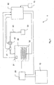
- FIG. 1 schematically describes an embodiment of an appliance 1 for producing hot drinks according to the invention comprising a tank 10 for containing water at atmospheric pressure, a water heating device 30 comprising a heat source 32, a pump 20 for feeding water from tank 10 to device 30, a seat 50 for containing a product for producing a hot drink, a duct 40 for feeding hot water from device 30 to seat 50, a first sensor 31 associated with device 30, a second sensor 41 associated with duct 40, a solenoid valve 42, selection means 70 and control means 60.
- Device 30 can, for example, be a conventional boiler of the stagnant water type or a conventional instant hot water generator wherein water does not stagnate and is heated by flowing, for example, along a labyrinth path.
- Heat source 32 typically is an armoured electrical resistance of the conventional type.
- Temperature sensors 31, 41 are, for example, conventional negative temperature coefficient (NTC) probes.
- NTC negative temperature coefficient
- sensor 31 is housed into device 30 for directly detecting the temperature of the water contained in the device.
- Sensor 41 is in contact with the outer wall of duct 40 at a point of the same duct 40 and is adapted to detect the duct temperature at that point.
- Solenoid valve 42, pump. 20 and tank 10 are made according to conventional techniques well known in the art.
- Solenoid valve 42 is adapted to block/allow the water flow along duct 40 towards seat 50.
- control means 60 is adapted to activate pump 20 so that it pumps water from tank 10 to device 30 and to open solenoid valve 42 to allow the water flow, at a pressure determined by the thrust of pump 20, towards seat 50.
- the hot water is produced thanks to the arrival of hot water at a predetermined temperature (for example 90°C) and at a predetermined pressure on seat 50 and to the flow of hot water through the product contained in seat 50.
- An infusion pressure originates at seat 50, generated by the combination of two factors 1) thrust of pump 20 and 2) resistance offered by the product to the water flow through the same.
- Device 30 advantageously comprises also a safety system (not shown) of the conventional type adapted to cut off the supply to the heat source 32 in the event of overheating of the same.
- the appliance further comprises suitable indicator means (not shown) adapted to indicate to the user that the appliance is ready for use, once the optimum temperature for the water contained in device 30 is reached.
- Appliance 1 can, for example, be used for producing a single hot drink, such as coffee, or more hot drinks such as coffee, tea, hot chocolate, infusions of various types, barley, hot milk, cappuccinos, milk with coffee, etc.
- a single hot drink such as coffee
- hot drinks such as coffee, tea, hot chocolate, infusions of various types, barley, hot milk, cappuccinos, milk with coffee, etc.
- appliance 1 advantageously comprises also the selection means 70 adapted to allow the user to select the desired type of hot drink, among the plurality of hot drinks that can be produced by appliance 1.
- the present invention can be used for implementing any appliance for producing hot drinks such as, for example, an espresso coffee maker for a typical household or bar use or an automatic dispenser of hot drinks for a typical company use, typically working with loose powder or granule products, or an appliance for making hot drinks working with products pre-packaged into suitable wafers, capsules or bags.
- any appliance for producing hot drinks such as, for example, an espresso coffee maker for a typical household or bar use or an automatic dispenser of hot drinks for a typical company use, typically working with loose powder or granule products, or an appliance for making hot drinks working with products pre-packaged into suitable wafers, capsules or bags.
- Seat 50 shall therefore be shaped and manufactured according to conventional techniques so as to house the products (loose or pre-packaged) intended to be used with the type of appliance considered.
- seat 50 can be adapted to be removed from appliance 1 to allow the user to arrange the desired product therein such as, for example, in the case of some types of espresso coffee makers for household or bar use wherein the seat is provided with a grip and is adapted to be turned into two opposed directions by the user for allowing the removal/introduction.
- seat 50 could be incorporated in appliance 1 and could be adapted to allow the user, according to techniques well known in the art, to introduce the pre-packaged wafer or capsule product therein (such as in the case of appliances for preparing hot drinks working with pre-packaged products)' or it could be adapted to receive the loose product from special refillable containers housed into the appliance (such as in the case of automatic hot drink dispensers).
- duct 40 starts.from device 30 to move away therefrom and ends in the proximity of seat 50, arranged laterally to device 30.
- FIG. 2 shows an embodiment of appliance 1 which is totally similar to that shown in figure 1 except for the fact that seat 50 is arranged below device 30 and that duct 40, which starts from device 30, ends in the proximity of seat 50 passing inside device 30.
- This embodiment is advantageous because it allows obtaining a more compactly shaped appliance. Moreover, it advantageously allows limiting the temperature drop phenomenon of the water flowing along the duct, since the walls of the portion of duct 40 inside appliance 30 heat up also in the absence of hot water flow therein.
- control means 60 is adapted to switch on/switch off the heat source 32 based on the temperature detected by sensors 31, 41 (and, if present, 41a).
- the optimum production temperature range is comprised between 90 and 92 °C, for tea and other similar drinks between 80 - 85°C.
- the above algorithm shall be defined based on the type of product considered. If appliance 1 shall produce a plurality of hot drinks, the control means 60 shall be adapted to store a plurality of algorithms, one for each product or set of products having the same optimum production temperature range of the hot drink. The control means 60, moreover, shall be adapted to use the appropriate algorithm according to the hot drink to be produced, for example selected by the user by the above selections means 70.
- the above algorithm is defined also based on other factors that affect the sensitivity of sensor 41 and the temperature drop undergone by the water that flows through duct 40 such as the position of the second sensor 41 along duct 40, the length of duct 40, the diameter of duct 40, the thickness of the walls of duct 40 and the arrangement of duct 40 inside appliance 1.
- a long duct 40 implies a higher temperature drop of the water flowing therethrough compared to a short duct 40
- a duct 40 arranged outside and away from device 30 implies a higher temperature drop compared to a duct 40 arranged in contact with the walls of device 30 or inside the same (as shown in figure 2 ).
- a sensor arranged toward the end of the duct allows detecting information on the temperature of water in the proximity of the product but can cause delays in the continuous adjustment of the water temperature due to thermal inertia.
- a sensor arranged at the beginning of duct 30 allows improving the continuous water temperature adjustment in terms of thermal inertia but does not directly detect information on the temperature of water in the proximity of the product.
- control means 60 shall therefore be adapted to continuously read (for example every 0.1 or 0.01 s) the value of temperatures Tc1 and Tc2 detected by the two sensors associated with the duct, to determine the values of parameters X1 and X2 from the curves shown, to calculate the optimum temperature value Td through the above algorithm and to adjust the temperature vale of the water contained in device 30 accordingly, by switching on/switching off the heat source 32.
- control means 60 is adapted to switch on the heat source 32 and to start, according to the invention, a continuous process of adjustment of the temperature of water contained in device 30 based on the temperature detected by the sensor/s associated with the duct.
- control means 60 is adapted to check the temperature detected by the sensor/s associated with the duct and, upon each check carried out, to
- the appliance 1 of the invention allows keeping the temperature of the water that reaches the product constantly within the optimum temperature range for that specific product.
- the appliance of the invention allows achieving these advantages without substantially affecting the cost of the same.
- it only requires the use of at least one further temperature sensor associated with the duct (which is a standard product available on the market at very low cost) and the use of control means (e.g., a microprocessor), already present in a conventional appliance, for implementing the adjustment of the water temperature according to the method of the invention.
- control means e.g., a microprocessor
- the appliance of the invention can comprise a plurality of seats for producing a plurality of drinks and a single duct or multiple ducts for feeding water to the various seats.
- the appliance can comprise at least one temperature sensor associated with each duct, or with a portion thereof, and the control means shall be adapted to set the temperature of the water contained in the device based on the temperature detected by the temperature sensor associated with the duct that feeds the water to the seat from time to time used.
- the temperature, of the water that reaches such seat/s could be adjusted by using only the temperature sensor 31 associated with the water heating device 30 and the use of one or more temperature sensors associated with the duct/s for feeding water to such seat/s could be avoided.
- the appliance of the invention can comprise one or more ducts intended for the simple dispensing of hot water. Also in this case, where a fine adjustment of the temperature of the hot water dispensed is not required, the temperature adjustment could be carried out using only the temperature sensor 31 associated with the water heating device 30, without the need of associating any temperature sensor to such duct/s.
- a suitable number of temperature sensors to be associated with the single duct and a suitable arrangement of the various sensors therealong shall have to be provided, so as to be able to determine an optimum value to which the temperature of the water contained in the device should be brought which should allow obtaining, for the water that reaches each seat, the desired production temperature for a preselected product.
Landscapes
- Engineering & Computer Science (AREA)
- Food Science & Technology (AREA)
- Apparatus For Making Beverages (AREA)
- Thermally Insulated Containers For Foods (AREA)
- Vending Machines For Individual Products (AREA)
- Commercial Cooking Devices (AREA)
- Non-Alcoholic Beverages (AREA)
- General Preparation And Processing Of Foods (AREA)
- Dairy Products (AREA)
Priority Applications (1)
| Application Number | Priority Date | Filing Date | Title |
|---|---|---|---|
| PL05750140T PL1898757T3 (pl) | 2005-05-17 | 2005-05-17 | Urządzenie do wytwarzania gorących napojów |
Applications Claiming Priority (1)
| Application Number | Priority Date | Filing Date | Title |
|---|---|---|---|
| PCT/IT2005/000279 WO2006123370A1 (en) | 2005-05-17 | 2005-05-17 | Appliance for producing hot drinks |
Publications (2)
| Publication Number | Publication Date |
|---|---|
| EP1898757A1 EP1898757A1 (en) | 2008-03-19 |
| EP1898757B1 true EP1898757B1 (en) | 2009-09-02 |
Family
ID=35056892
Family Applications (2)
| Application Number | Title | Priority Date | Filing Date |
|---|---|---|---|
| EP05750140A Not-in-force EP1898757B1 (en) | 2005-05-17 | 2005-05-17 | Appliance for producing hot drinks |
| EP06742896A Not-in-force EP1898758B1 (en) | 2005-05-17 | 2006-05-12 | Appliance for producing hot drinks |
Family Applications After (1)
| Application Number | Title | Priority Date | Filing Date |
|---|---|---|---|
| EP06742896A Not-in-force EP1898758B1 (en) | 2005-05-17 | 2006-05-12 | Appliance for producing hot drinks |
Country Status (12)
| Country | Link |
|---|---|
| US (3) | US20080190298A1 (it) |
| EP (2) | EP1898757B1 (it) |
| JP (2) | JP4914980B2 (it) |
| CN (2) | CN101208033B (it) |
| AT (2) | ATE441347T1 (it) |
| AU (2) | AU2005331987B2 (it) |
| DE (2) | DE602005016468D1 (it) |
| ES (2) | ES2332279T3 (it) |
| NZ (1) | NZ563441A (it) |
| PL (2) | PL1898757T3 (it) |
| PT (2) | PT1898757E (it) |
| WO (2) | WO2006123370A1 (it) |
Cited By (1)
| Publication number | Priority date | Publication date | Assignee | Title |
|---|---|---|---|---|
| WO2017141281A1 (en) | 2016-02-19 | 2017-08-24 | Sandenvendo Europe S.P.A. | System and method for preparing beverages |
Families Citing this family (29)
| Publication number | Priority date | Publication date | Assignee | Title |
|---|---|---|---|---|
| DE102005030822A1 (de) * | 2005-07-01 | 2007-01-11 | Krones Ag | Verfahren und Vorrichtung zum Überwachen eines Verdampfers |
| EP1886605A1 (en) * | 2006-08-08 | 2008-02-13 | CME di Faccinti A. | Machine for the preparation of coffee and the like |
| IT1393999B1 (it) * | 2009-04-01 | 2012-05-17 | Rancilio Macchine Caffe | Macchina per la preparazione di infusi, in particolare caffe' espresso, gruppo erogatore e metodo di realizzazione della stessa |
| US8006611B2 (en) * | 2009-04-22 | 2011-08-30 | Uni-Splendor Corp. | Water feeding device of hot drink maker |
| DE102009036089A1 (de) * | 2009-08-04 | 2011-02-17 | Wmf Württembergische Metallwarenfabrik Ag | Einrichtung zur Bevorratung von Milch |
| EP2397054A1 (de) | 2010-06-15 | 2011-12-21 | Jura Elektroapparate AG | Brühvorrichtung mit einem Kaffee-Nacherhitzer |
| KR101990421B1 (ko) | 2011-11-23 | 2019-06-18 | 스타벅스 코포레이션 | 음료를 브루잉하기 위한 장치, 시스템 및 방법 |
| ITRE20110109A1 (it) * | 2011-12-07 | 2013-06-08 | Redox S R L | Macchina da caffe' a risparmio energetico |
| DE202012009074U1 (de) * | 2012-09-21 | 2012-11-08 | Eugster/Frismag Ag | Vorrichtung zur Bereitung von wahlweise kaltem oder warmem Milchschaum oder Abgabe wahlweise kalter oder warmer Milch |
| WO2015039264A1 (zh) * | 2013-09-23 | 2015-03-26 | 刘宗熹 | 中央定温供水饮料制备装置 |
| WO2015077237A2 (en) | 2013-11-20 | 2015-05-28 | Starbucks Corporation D/B/A Starbucks Coffee Company | Cooking system power management |
| USD738667S1 (en) | 2013-11-20 | 2015-09-15 | Starbucks Corporation | Beverage brewing apparatus |
| CN103892711B (zh) * | 2014-04-02 | 2016-04-13 | 深圳市赛亿科技开发有限公司 | 一种多参数快速加热饮水器及其控制方法 |
| US10759646B2 (en) * | 2014-07-29 | 2020-09-01 | Societe Des Produits Nestle S.A. | Instant tube heater with homogenous temperature control |
| EP3114972B1 (de) * | 2015-07-09 | 2017-08-23 | Qbo Coffee GmbH | Getränkezubereitungsmaschine |
| CN107401731A (zh) * | 2016-05-19 | 2017-11-28 | 苏州昆仑工业设计有限公司 | 一种用于灯具的喷雾式自动降温装置 |
| JP6846699B2 (ja) * | 2017-01-11 | 2021-03-24 | パナソニックIpマネジメント株式会社 | 給湯装置 |
| CN106667271A (zh) * | 2017-03-01 | 2017-05-17 | 深圳鼎加弘思饮品科技有限公司 | 饮品机的温度补偿装置及其控制方法和饮品机 |
| IT201700032502A1 (it) * | 2017-03-24 | 2018-09-24 | La Marzocco Srl | Macchina per caffè espresso con sistema perfezionato di regolazione della temperatura dell’acqua e metodo di regolazione della temperatura dell’acqua di una macchina per caffè espresso |
| US11523706B2 (en) * | 2017-04-11 | 2022-12-13 | Societe Des Produits Nestle S.A. | Beverage preparation apparatus with beverage draining means |
| JP6844422B2 (ja) * | 2017-05-31 | 2021-03-17 | タイガー魔法瓶株式会社 | 飲料製造装置 |
| CN109820422A (zh) * | 2017-11-23 | 2019-05-31 | 德隆奇电器单一股东有限责任公司 | 制备饮料的机器和方法 |
| CN108378700B (zh) * | 2018-03-07 | 2020-03-27 | 佛山市顺德区美的饮水机制造有限公司 | 一种饮水装置水温的控制方法、控制系统及饮水装置 |
| JP7217494B2 (ja) * | 2018-08-07 | 2023-02-03 | 株式会社大都技研 | 飲料製造装置 |
| EP3643210A1 (de) | 2018-10-25 | 2020-04-29 | Jura Elektroapparate AG | Verfahren zum erzeugen eines kaffeegetränks in einem kaffeeautomaten |
| IT201900001623A1 (it) | 2019-02-05 | 2020-08-05 | La Marzocco Srl | Macchina macina caffè con sistema di dosatura perfezionato e relativo metodo |
| CN112263143B (zh) * | 2020-10-23 | 2022-06-14 | 佛山市顺德区美的饮水机制造有限公司 | 用于即热式饮水设备的方法、装置、存储介质及处理器 |
| CN112369920B (zh) * | 2020-10-23 | 2022-07-01 | 佛山市顺德区美的饮水机制造有限公司 | 用于即热式饮水设备的方法、处理器、装置及存储介质 |
| JP7113278B2 (ja) * | 2021-02-15 | 2022-08-05 | パナソニックIpマネジメント株式会社 | 給湯装置 |
Family Cites Families (22)
| Publication number | Priority date | Publication date | Assignee | Title |
|---|---|---|---|---|
| US3100434A (en) * | 1960-01-08 | 1963-08-13 | George R Bunn | Coffee making machine |
| DE3316158A1 (de) * | 1983-05-03 | 1984-11-08 | Württembergische Metallwarenfabrik AG, 7340 Geislingen | Kaffeemaschine zum wahlweisen bruehen von normalkaffee oder espresso |
| US4613745A (en) | 1984-04-06 | 1986-09-23 | North American Systems, Inc. | Electric water heating apparatus for a drip coffee maker |
| IT1235261B (it) * | 1989-01-30 | 1992-06-26 | Illycaffe Spa | Macchina da caffe'. |
| DE3937000C2 (de) * | 1989-11-07 | 1995-05-04 | Willi Marco | Kaffeemaschine zur wahlweisen Zubereitung von Espresso-Kaffee oder Filterkaffee |
| US5440972A (en) * | 1991-08-01 | 1995-08-15 | English; Philip H. | Portable beverage brewing device |
| CN2136624Y (zh) * | 1992-03-05 | 1993-06-23 | 上海申美饮料食品有限公司 | 自动配料热饮机 |
| CN2136421Y (zh) * | 1992-10-22 | 1993-06-16 | 上海百事可乐饮料有限公司 | 热饮机 |
| DE4435100A1 (de) * | 1994-09-30 | 1996-04-04 | Braun Ag | Verfahren zur Regelung der Wassertemperatur in einer Brühgetränkemaschine |
| US5551331A (en) | 1995-05-15 | 1996-09-03 | Grindmaster Corporation | Espresso apparatus with improved heating of the brew head and boiler |
| DE69507147T2 (de) * | 1995-10-31 | 1999-07-01 | Illycaffe Spa | Verbesserte Kaffeemaschine |
| JP3120746B2 (ja) * | 1997-01-20 | 2000-12-25 | 松下電器産業株式会社 | コーヒー抽出器 |
| US6164189A (en) * | 1999-10-12 | 2000-12-26 | Bunn-O-Matic Corporation | Heated water dispensing system |
| EP1312291A1 (de) * | 2001-11-20 | 2003-05-21 | M. Schaerer AG | Kaffeemaschine |
| CN2560285Y (zh) * | 2002-03-28 | 2003-07-16 | 蔡文军 | 一种全自动热饮料饮水机 |
| JP4012006B2 (ja) * | 2002-08-09 | 2007-11-21 | ホシザキ電機株式会社 | 湯供給装置 |
| EP1433403A1 (de) * | 2002-12-24 | 2004-06-30 | John Schild | Espresso-Kaffeemaschine und Verfahren zum Betrieb derselben |
| JP2004332985A (ja) * | 2003-05-02 | 2004-11-25 | Inax Corp | 即湯システム |
| US7017472B2 (en) * | 2003-10-10 | 2006-03-28 | Hp Intellectual Corp. | Brewing apparatus water temperature control |
| JP2005338913A (ja) * | 2004-05-24 | 2005-12-08 | Fuji Electric Retail Systems Co Ltd | カップ式飲料自動販売機 |
| US20060011068A1 (en) * | 2004-07-19 | 2006-01-19 | Spencer William L | Coffee maker and method of use |
| US7401545B2 (en) * | 2004-11-09 | 2008-07-22 | Nestec S.A. | Method and apparatus for optimizing variable liquid temperatures |
-
2005
- 2005-05-17 CN CN2005800502581A patent/CN101208033B/zh not_active Expired - Fee Related
- 2005-05-17 DE DE602005016468T patent/DE602005016468D1/de active Active
- 2005-05-17 PT PT05750140T patent/PT1898757E/pt unknown
- 2005-05-17 PL PL05750140T patent/PL1898757T3/pl unknown
- 2005-05-17 AU AU2005331987A patent/AU2005331987B2/en not_active Ceased
- 2005-05-17 US US11/914,735 patent/US20080190298A1/en not_active Abandoned
- 2005-05-17 JP JP2008511869A patent/JP4914980B2/ja not_active Expired - Fee Related
- 2005-05-17 EP EP05750140A patent/EP1898757B1/en not_active Not-in-force
- 2005-05-17 AT AT05750140T patent/ATE441347T1/de not_active IP Right Cessation
- 2005-05-17 WO PCT/IT2005/000279 patent/WO2006123370A1/en active Application Filing
- 2005-05-17 ES ES05750140T patent/ES2332279T3/es active Active
-
2006
- 2006-05-12 WO PCT/EP2006/004484 patent/WO2006122720A1/en active Application Filing
- 2006-05-12 PT PT06742896T patent/PT1898758E/pt unknown
- 2006-05-12 CN CN2006800226637A patent/CN101203164B/zh not_active Expired - Fee Related
- 2006-05-12 AT AT06742896T patent/ATE435606T1/de not_active IP Right Cessation
- 2006-05-12 ES ES06742896T patent/ES2329407T3/es active Active
- 2006-05-12 US US11/914,730 patent/US8176839B2/en not_active Expired - Fee Related
- 2006-05-12 PL PL06742896T patent/PL1898758T3/pl unknown
- 2006-05-12 EP EP06742896A patent/EP1898758B1/en not_active Not-in-force
- 2006-05-12 DE DE602006007707T patent/DE602006007707D1/de active Active
- 2006-05-12 JP JP2008511599A patent/JP5097109B2/ja not_active Expired - Fee Related
- 2006-05-12 AU AU2006246636A patent/AU2006246636B2/en not_active Ceased
- 2006-05-17 NZ NZ563441A patent/NZ563441A/en not_active IP Right Cessation
-
2012
- 2012-03-30 US US13/435,891 patent/US20120222666A1/en not_active Abandoned
Cited By (1)
| Publication number | Priority date | Publication date | Assignee | Title |
|---|---|---|---|---|
| WO2017141281A1 (en) | 2016-02-19 | 2017-08-24 | Sandenvendo Europe S.P.A. | System and method for preparing beverages |
Also Published As
| Publication number | Publication date |
|---|---|
| PT1898757E (pt) | 2009-11-04 |
| CN101208033B (zh) | 2010-05-12 |
| CN101203164B (zh) | 2010-12-01 |
| AU2006246636A1 (en) | 2006-11-23 |
| WO2006123370A1 (en) | 2006-11-23 |
| AU2006246636B2 (en) | 2011-04-28 |
| US20120222666A1 (en) | 2012-09-06 |
| AU2005331987A1 (en) | 2006-11-23 |
| US20080190298A1 (en) | 2008-08-14 |
| ATE435606T1 (de) | 2009-07-15 |
| EP1898757A1 (en) | 2008-03-19 |
| JP2008540024A (ja) | 2008-11-20 |
| US8176839B2 (en) | 2012-05-15 |
| CN101203164A (zh) | 2008-06-18 |
| EP1898758A1 (en) | 2008-03-19 |
| DE602005016468D1 (it) | 2009-10-15 |
| PT1898758E (pt) | 2009-09-11 |
| WO2006122720A1 (en) | 2006-11-23 |
| AU2005331987B2 (en) | 2011-03-31 |
| JP2008540002A (ja) | 2008-11-20 |
| PL1898758T3 (pl) | 2009-12-31 |
| ES2332279T3 (es) | 2010-02-01 |
| JP5097109B2 (ja) | 2012-12-12 |
| DE602006007707D1 (de) | 2009-08-20 |
| EP1898758B1 (en) | 2009-07-08 |
| NZ563441A (en) | 2010-08-27 |
| PL1898757T3 (pl) | 2010-02-26 |
| ES2329407T3 (es) | 2009-11-25 |
| ATE441347T1 (de) | 2009-09-15 |
| CN101208033A (zh) | 2008-06-25 |
| US20080264264A1 (en) | 2008-10-30 |
| JP4914980B2 (ja) | 2012-04-11 |
Similar Documents
| Publication | Publication Date | Title |
|---|---|---|
| EP1898757B1 (en) | Appliance for producing hot drinks | |
| AU2018232987B2 (en) | Apparatus and method for an improved coffee maker | |
| RU2568580C2 (ru) | Кофеварочная машина с заварочным устройством и подогревателем для кофе, соединенным с заварочным устройством | |
| RU2565657C2 (ru) | Быстрый разогрев устройства тепловой обработки, например, для кофемашины | |
| WO2005107540A1 (en) | Single/multiple beverage machine | |
| EP3713457B1 (en) | Machine and method for preparing beverages | |
| NZ563442A (en) | Appliance for producing hot drinks |
Legal Events
| Date | Code | Title | Description |
|---|---|---|---|
| PUAI | Public reference made under article 153(3) epc to a published international application that has entered the european phase |
Free format text: ORIGINAL CODE: 0009012 |
|
| 17P | Request for examination filed |
Effective date: 20071121 |
|
| AK | Designated contracting states |
Kind code of ref document: A1 Designated state(s): AT BE BG CH CY CZ DE DK EE ES FI FR GB GR HU IE IS IT LI LT LU MC NL PL PT RO SE SI SK TR |
|
| 17Q | First examination report despatched |
Effective date: 20080513 |
|
| DAX | Request for extension of the european patent (deleted) | ||
| GRAP | Despatch of communication of intention to grant a patent |
Free format text: ORIGINAL CODE: EPIDOSNIGR1 |
|
| GRAS | Grant fee paid |
Free format text: ORIGINAL CODE: EPIDOSNIGR3 |
|
| GRAA | (expected) grant |
Free format text: ORIGINAL CODE: 0009210 |
|
| AK | Designated contracting states |
Kind code of ref document: B1 Designated state(s): AT BE BG CH CY CZ DE DK EE ES FI FR GB GR HU IE IS IT LI LT LU MC NL PL PT RO SE SI SK TR |
|
| REG | Reference to a national code |
Ref country code: CH Ref legal event code: EP |
|
| REG | Reference to a national code |
Ref country code: IE Ref legal event code: FG4D |
|
| REF | Corresponds to: |
Ref document number: 602005016468 Country of ref document: DE Date of ref document: 20091015 Kind code of ref document: P |
|
| REG | Reference to a national code |
Ref country code: PT Ref legal event code: SC4A Free format text: AVAILABILITY OF NATIONAL TRANSLATION Effective date: 20091028 |
|
| REG | Reference to a national code |
Ref country code: GR Ref legal event code: EP Ref document number: 20090402849 Country of ref document: GR |
|
| PG25 | Lapsed in a contracting state [announced via postgrant information from national office to epo] |
Ref country code: FI Free format text: LAPSE BECAUSE OF FAILURE TO SUBMIT A TRANSLATION OF THE DESCRIPTION OR TO PAY THE FEE WITHIN THE PRESCRIBED TIME-LIMIT Effective date: 20090902 Ref country code: LT Free format text: LAPSE BECAUSE OF FAILURE TO SUBMIT A TRANSLATION OF THE DESCRIPTION OR TO PAY THE FEE WITHIN THE PRESCRIBED TIME-LIMIT Effective date: 20090902 Ref country code: SE Free format text: LAPSE BECAUSE OF FAILURE TO SUBMIT A TRANSLATION OF THE DESCRIPTION OR TO PAY THE FEE WITHIN THE PRESCRIBED TIME-LIMIT Effective date: 20090902 |
|
| REG | Reference to a national code |
Ref country code: ES Ref legal event code: FG2A Ref document number: 2332279 Country of ref document: ES Kind code of ref document: T3 |
|
| LTIE | Lt: invalidation of european patent or patent extension |
Effective date: 20090902 |
|
| PG25 | Lapsed in a contracting state [announced via postgrant information from national office to epo] |
Ref country code: SI Free format text: LAPSE BECAUSE OF FAILURE TO SUBMIT A TRANSLATION OF THE DESCRIPTION OR TO PAY THE FEE WITHIN THE PRESCRIBED TIME-LIMIT Effective date: 20090902 |
|
| REG | Reference to a national code |
Ref country code: PL Ref legal event code: T3 |
|
| PG25 | Lapsed in a contracting state [announced via postgrant information from national office to epo] |
Ref country code: CY Free format text: LAPSE BECAUSE OF FAILURE TO SUBMIT A TRANSLATION OF THE DESCRIPTION OR TO PAY THE FEE WITHIN THE PRESCRIBED TIME-LIMIT Effective date: 20090902 |
|
| PG25 | Lapsed in a contracting state [announced via postgrant information from national office to epo] |
Ref country code: RO Free format text: LAPSE BECAUSE OF FAILURE TO SUBMIT A TRANSLATION OF THE DESCRIPTION OR TO PAY THE FEE WITHIN THE PRESCRIBED TIME-LIMIT Effective date: 20090902 Ref country code: CZ Free format text: LAPSE BECAUSE OF FAILURE TO SUBMIT A TRANSLATION OF THE DESCRIPTION OR TO PAY THE FEE WITHIN THE PRESCRIBED TIME-LIMIT Effective date: 20090902 Ref country code: IS Free format text: LAPSE BECAUSE OF FAILURE TO SUBMIT A TRANSLATION OF THE DESCRIPTION OR TO PAY THE FEE WITHIN THE PRESCRIBED TIME-LIMIT Effective date: 20100102 Ref country code: EE Free format text: LAPSE BECAUSE OF FAILURE TO SUBMIT A TRANSLATION OF THE DESCRIPTION OR TO PAY THE FEE WITHIN THE PRESCRIBED TIME-LIMIT Effective date: 20090902 |
|
| PG25 | Lapsed in a contracting state [announced via postgrant information from national office to epo] |
Ref country code: SK Free format text: LAPSE BECAUSE OF FAILURE TO SUBMIT A TRANSLATION OF THE DESCRIPTION OR TO PAY THE FEE WITHIN THE PRESCRIBED TIME-LIMIT Effective date: 20090902 |
|
| PG25 | Lapsed in a contracting state [announced via postgrant information from national office to epo] |
Ref country code: AT Free format text: LAPSE BECAUSE OF FAILURE TO SUBMIT A TRANSLATION OF THE DESCRIPTION OR TO PAY THE FEE WITHIN THE PRESCRIBED TIME-LIMIT Effective date: 20090902 Ref country code: BE Free format text: LAPSE BECAUSE OF FAILURE TO SUBMIT A TRANSLATION OF THE DESCRIPTION OR TO PAY THE FEE WITHIN THE PRESCRIBED TIME-LIMIT Effective date: 20090902 |
|
| PLBE | No opposition filed within time limit |
Free format text: ORIGINAL CODE: 0009261 |
|
| STAA | Information on the status of an ep patent application or granted ep patent |
Free format text: STATUS: NO OPPOSITION FILED WITHIN TIME LIMIT |
|
| PG25 | Lapsed in a contracting state [announced via postgrant information from national office to epo] |
Ref country code: DK Free format text: LAPSE BECAUSE OF FAILURE TO SUBMIT A TRANSLATION OF THE DESCRIPTION OR TO PAY THE FEE WITHIN THE PRESCRIBED TIME-LIMIT Effective date: 20090902 |
|
| 26N | No opposition filed |
Effective date: 20100603 |
|
| PG25 | Lapsed in a contracting state [announced via postgrant information from national office to epo] |
Ref country code: MC Free format text: LAPSE BECAUSE OF NON-PAYMENT OF DUE FEES Effective date: 20100531 |
|
| REG | Reference to a national code |
Ref country code: CH Ref legal event code: PL |
|
| PG25 | Lapsed in a contracting state [announced via postgrant information from national office to epo] |
Ref country code: CH Free format text: LAPSE BECAUSE OF NON-PAYMENT OF DUE FEES Effective date: 20100531 Ref country code: LI Free format text: LAPSE BECAUSE OF NON-PAYMENT OF DUE FEES Effective date: 20100531 |
|
| PG25 | Lapsed in a contracting state [announced via postgrant information from national office to epo] |
Ref country code: IE Free format text: LAPSE BECAUSE OF NON-PAYMENT OF DUE FEES Effective date: 20100517 |
|
| PGFP | Annual fee paid to national office [announced via postgrant information from national office to epo] |
Ref country code: DE Payment date: 20120529 Year of fee payment: 8 Ref country code: NL Payment date: 20120530 Year of fee payment: 8 |
|
| PGFP | Annual fee paid to national office [announced via postgrant information from national office to epo] |
Ref country code: GB Payment date: 20120525 Year of fee payment: 8 Ref country code: FR Payment date: 20120607 Year of fee payment: 8 Ref country code: GR Payment date: 20120530 Year of fee payment: 8 Ref country code: PL Payment date: 20120504 Year of fee payment: 8 |
|
| PG25 | Lapsed in a contracting state [announced via postgrant information from national office to epo] |
Ref country code: HU Free format text: LAPSE BECAUSE OF FAILURE TO SUBMIT A TRANSLATION OF THE DESCRIPTION OR TO PAY THE FEE WITHIN THE PRESCRIBED TIME-LIMIT Effective date: 20100303 Ref country code: LU Free format text: LAPSE BECAUSE OF NON-PAYMENT OF DUE FEES Effective date: 20100517 Ref country code: BG Free format text: LAPSE BECAUSE OF FAILURE TO SUBMIT A TRANSLATION OF THE DESCRIPTION OR TO PAY THE FEE WITHIN THE PRESCRIBED TIME-LIMIT Effective date: 20090902 |
|
| PG25 | Lapsed in a contracting state [announced via postgrant information from national office to epo] |
Ref country code: TR Free format text: LAPSE BECAUSE OF FAILURE TO SUBMIT A TRANSLATION OF THE DESCRIPTION OR TO PAY THE FEE WITHIN THE PRESCRIBED TIME-LIMIT Effective date: 20090902 |
|
| PGFP | Annual fee paid to national office [announced via postgrant information from national office to epo] |
Ref country code: ES Payment date: 20120528 Year of fee payment: 8 |
|
| PGFP | Annual fee paid to national office [announced via postgrant information from national office to epo] |
Ref country code: IT Payment date: 20130506 Year of fee payment: 9 Ref country code: PT Payment date: 20130507 Year of fee payment: 9 |
|
| REG | Reference to a national code |
Ref country code: NL Ref legal event code: V1 Effective date: 20131201 |
|
| GBPC | Gb: european patent ceased through non-payment of renewal fee |
Effective date: 20130517 |
|
| PG25 | Lapsed in a contracting state [announced via postgrant information from national office to epo] |
Ref country code: DE Free format text: LAPSE BECAUSE OF NON-PAYMENT OF DUE FEES Effective date: 20131203 |
|
| REG | Reference to a national code |
Ref country code: GR Ref legal event code: ML Ref document number: 20090402849 Country of ref document: GR Effective date: 20131204 |
|
| REG | Reference to a national code |
Ref country code: DE Ref legal event code: R119 Ref document number: 602005016468 Country of ref document: DE Effective date: 20131203 |
|
| PG25 | Lapsed in a contracting state [announced via postgrant information from national office to epo] |
Ref country code: GR Free format text: LAPSE BECAUSE OF NON-PAYMENT OF DUE FEES Effective date: 20131204 Ref country code: NL Free format text: LAPSE BECAUSE OF NON-PAYMENT OF DUE FEES Effective date: 20131201 |
|
| REG | Reference to a national code |
Ref country code: FR Ref legal event code: ST Effective date: 20140131 |
|
| PG25 | Lapsed in a contracting state [announced via postgrant information from national office to epo] |
Ref country code: GB Free format text: LAPSE BECAUSE OF NON-PAYMENT OF DUE FEES Effective date: 20130517 |
|
| PG25 | Lapsed in a contracting state [announced via postgrant information from national office to epo] |
Ref country code: FR Free format text: LAPSE BECAUSE OF NON-PAYMENT OF DUE FEES Effective date: 20130531 |
|
| PG25 | Lapsed in a contracting state [announced via postgrant information from national office to epo] |
Ref country code: PL Free format text: LAPSE BECAUSE OF NON-PAYMENT OF DUE FEES Effective date: 20130517 |
|
| REG | Reference to a national code |
Ref country code: PL Ref legal event code: LAPE |
|
| REG | Reference to a national code |
Ref country code: PT Ref legal event code: MM4A Free format text: LAPSE DUE TO NON-PAYMENT OF FEES Effective date: 20141117 |
|
| PG25 | Lapsed in a contracting state [announced via postgrant information from national office to epo] |
Ref country code: PT Free format text: LAPSE BECAUSE OF NON-PAYMENT OF DUE FEES Effective date: 20141117 |
|
| PG25 | Lapsed in a contracting state [announced via postgrant information from national office to epo] |
Ref country code: IT Free format text: LAPSE BECAUSE OF NON-PAYMENT OF DUE FEES Effective date: 20140517 |
|
| REG | Reference to a national code |
Ref country code: ES Ref legal event code: FD2A Effective date: 20150626 |
|
| PG25 | Lapsed in a contracting state [announced via postgrant information from national office to epo] |
Ref country code: ES Free format text: LAPSE BECAUSE OF NON-PAYMENT OF DUE FEES Effective date: 20140518 |