EP1898066A2 - Gas turbine system - Google Patents
Gas turbine system Download PDFInfo
- Publication number
- EP1898066A2 EP1898066A2 EP07017395A EP07017395A EP1898066A2 EP 1898066 A2 EP1898066 A2 EP 1898066A2 EP 07017395 A EP07017395 A EP 07017395A EP 07017395 A EP07017395 A EP 07017395A EP 1898066 A2 EP1898066 A2 EP 1898066A2
- Authority
- EP
- European Patent Office
- Prior art keywords
- air
- compressor
- combustor
- turbine
- recuperator
- Prior art date
- Legal status (The legal status is an assumption and is not a legal conclusion. Google has not performed a legal analysis and makes no representation as to the accuracy of the status listed.)
- Granted
Links
- 239000007789 gas Substances 0.000 claims description 69
- 239000000446 fuel Substances 0.000 claims description 14
- 239000000567 combustion gas Substances 0.000 claims description 11
- 230000007423 decrease Effects 0.000 abstract description 19
- XLYOFNOQVPJJNP-UHFFFAOYSA-N water Substances O XLYOFNOQVPJJNP-UHFFFAOYSA-N 0.000 description 15
- 230000004044 response Effects 0.000 description 13
- 238000002485 combustion reaction Methods 0.000 description 10
- 230000003247 decreasing effect Effects 0.000 description 9
- 230000001276 controlling effect Effects 0.000 description 5
- 238000011084 recovery Methods 0.000 description 4
- 238000010586 diagram Methods 0.000 description 3
- 239000007921 spray Substances 0.000 description 3
- 239000000872 buffer Substances 0.000 description 2
- 230000008859 change Effects 0.000 description 2
- 230000000694 effects Effects 0.000 description 2
- 235000013365 dairy product Nutrition 0.000 description 1
- 230000003111 delayed effect Effects 0.000 description 1
- 230000006866 deterioration Effects 0.000 description 1
- 230000006872 improvement Effects 0.000 description 1
- 238000002347 injection Methods 0.000 description 1
- 239000007924 injection Substances 0.000 description 1
- 230000004048 modification Effects 0.000 description 1
- 238000012986 modification Methods 0.000 description 1
- 230000001105 regulatory effect Effects 0.000 description 1
- 238000011144 upstream manufacturing Methods 0.000 description 1
Images

Classifications
-
- F—MECHANICAL ENGINEERING; LIGHTING; HEATING; WEAPONS; BLASTING
- F02—COMBUSTION ENGINES; HOT-GAS OR COMBUSTION-PRODUCT ENGINE PLANTS
- F02C—GAS-TURBINE PLANTS; AIR INTAKES FOR JET-PROPULSION PLANTS; CONTROLLING FUEL SUPPLY IN AIR-BREATHING JET-PROPULSION PLANTS
- F02C3/00—Gas-turbine plants characterised by the use of combustion products as the working fluid
- F02C3/20—Gas-turbine plants characterised by the use of combustion products as the working fluid using a special fuel, oxidant, or dilution fluid to generate the combustion products
- F02C3/30—Adding water, steam or other fluids for influencing combustion, e.g. to obtain cleaner exhaust gases
- F02C3/305—Increasing the power, speed, torque or efficiency of a gas turbine or the thrust of a turbojet engine by injecting or adding water, steam or other fluids
-
- F—MECHANICAL ENGINEERING; LIGHTING; HEATING; WEAPONS; BLASTING
- F02—COMBUSTION ENGINES; HOT-GAS OR COMBUSTION-PRODUCT ENGINE PLANTS
- F02C—GAS-TURBINE PLANTS; AIR INTAKES FOR JET-PROPULSION PLANTS; CONTROLLING FUEL SUPPLY IN AIR-BREATHING JET-PROPULSION PLANTS
- F02C7/00—Features, components parts, details or accessories, not provided for in, or of interest apart form groups F02C1/00 - F02C6/00; Air intakes for jet-propulsion plants
- F02C7/08—Heating air supply before combustion, e.g. by exhaust gases
-
- F—MECHANICAL ENGINEERING; LIGHTING; HEATING; WEAPONS; BLASTING
- F05—INDEXING SCHEMES RELATING TO ENGINES OR PUMPS IN VARIOUS SUBCLASSES OF CLASSES F01-F04
- F05D—INDEXING SCHEME FOR ASPECTS RELATING TO NON-POSITIVE-DISPLACEMENT MACHINES OR ENGINES, GAS-TURBINES OR JET-PROPULSION PLANTS
- F05D2260/00—Function
- F05D2260/20—Heat transfer, e.g. cooling
- F05D2260/212—Heat transfer, e.g. cooling by water injection
-
- F—MECHANICAL ENGINEERING; LIGHTING; HEATING; WEAPONS; BLASTING
- F05—INDEXING SCHEMES RELATING TO ENGINES OR PUMPS IN VARIOUS SUBCLASSES OF CLASSES F01-F04
- F05D—INDEXING SCHEME FOR ASPECTS RELATING TO NON-POSITIVE-DISPLACEMENT MACHINES OR ENGINES, GAS-TURBINES OR JET-PROPULSION PLANTS
- F05D2270/00—Control
- F05D2270/01—Purpose of the control system
- F05D2270/05—Purpose of the control system to affect the output of the engine
- F05D2270/053—Explicitly mentioned power
Definitions
- the present invention relates to a gas turbine system, particularly a gas turbine system preferably applicable to a high humidity electric power generating plant in which a humidity of a gaseous matter to be supplied to a gas turbine is increased to improve an output power and an efficiency.
- a high humidity gas turbine system in which a water is injected into a gaseous matter (air) to be supplied to a gas turbine so that an output power and an efficiency are improved, is of high efficiency in comparison with a conventional gas turbine electric power generating plant, and is expected to be used in a compact electric generator for factory or a cogeneration system. Further, since a flexible operation for a dairy start-stop and load variation is needed in the compact electric generating plant or the like, an improvement in load following operation is desired.
- a high humidity gas turbine system for the flexible load following operation including a bypass system bypassing a humidification tower to directly supply a part of an air compressed by a compressor to a downstream side of the humidification tower, and a humidifier connected to the bypass system to adjust a humidity of the part of air with a spray injection, is known.
- a bypass system bypassing a humidification tower to directly supply a part of an air compressed by a compressor to a downstream side of the humidification tower, and a humidifier connected to the bypass system to adjust a humidity of the part of air with a spray injection
- the humidity adjusting means as described in JP-A-2005-307861 has the following problem in a response to the load variation.
- the high humidity gas turbine system has a distinctive feature of high efficiency for a partial load, because a heat exchange between an exhaust gas discharged from a gas turbine and an air for combustion is performed by a recuperator to heat the an air for combustion to decrease a fuel consumption in a combustor.
- a compressor inlet guide vane is arranged as an upstream side of the compressor to adjust a flow rate of the air to be supplied to the compressor during the partial load operation so that an exhaust temperature during the partial load operation is made close to an exhaust temperature during a normal load operation to improve the efficiency of operation.
- the pressure chambers as buffers cause a delay of a response of air to an increase of the load from the partial load operation with a throttled air flow rate, so that a response to the load increase is deteriorated.
- an excessive thermal capacity of the recuperator restrains the temperature of the air for combustion from decreasing when the load decreases so that a response to the decrease in load is deteriorated.
- An object of the present invention is to provide a gas turbine system whose characteristic in response to the load variation such as the load increase or decrease is improved.
- the responsibility to the load variation such as the load increase or decrease is improved.
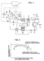
- Fig. 1 is a control system view showing the gas turbine system as the embodiment of the invention.
- An air to be used in a combustion for a gas turbine 1 is adjusted by a compressor inlet guide vane 18, subsequently its humidity is increased by an intake air atomizer 10, subsequently the air is compressed by a compressor, subsequently a heat exchange for the air is performed in an air cooler 7, subsequently its humidity is increased by a humidification tower 8, and subsequently the air is heated by a recuperator 11.
- a thermal energy source of the recuperator 11 is an exhaust gas supplied from the gas turbine 1. The thermal energy is absorbed by the air from the recuperator 11 to obtain the air of high temperature and high humidity for combustion.
- the fuel whose flow rate is adjusted by a fuel regulating control valve 5 is combusted in a combustor 3 with the air of high humidity and high temperature for combustion.
- a combustion gas formed by the fuel and the air with the vapor drives the gas turbine 3, and subsequently discharged as an exhaust gas to an outside of the turbine through an economizer 12 and a gas duct 17.
- a thermal energy of the exhaust gas discharged to the outside of the turbine is collected by a recuperator 11 to heat the air for combustion.
- the humidity included by the combustion exhaust gas is collected by a water recovery system 9.
- a water is sprayed in the gas duct 17 to condense the humidity in the gas so that the water drops to be collected.
- the exhaust gas is discharged into the atmosphere through a stack 16 after collecting the water.
- a driving force generated by the gas turbine is transmitted to the compressor 2 and a generator 4 through a shaft 6.
- a part of the driving force is used to pressurize the air in the compressor. Further, the generator 4 converts the driving force to an electric power.
- the water collected by the water recovery system 9 is stored by a water collecting tank and supplied by pumps 13 and 14 to the spray and the water recovery system 9 to be reused as a humidification water for the spray and a sprayed water for the water recovery system 9.
- the water discharged to the atmosphere through the stack 16 is recovered by a make-up water pump 15.
- the gas turbine system as shown in fig. 1 includes a pressure container bypass valve 19 for enabling a part of the air compressed by the compressor to flow directly to the combustor while preventing the part of the air flowing through the humidification tower 8 and the recuperator 11, a turbine bypass valve 20 for enabling a part of the humidified air to be discharged to an exhaust duct while preventing the part of the humidified air from flowing through the turbine 1 after the heat exchange between the humidified air and the turbine exhaust gas is performed in the recuperator 11, and a turbine control system 21 for controlling operations of the bypass valves 19 and 20 as described below.
- Fig. 2 is a control explanation view of the compressor inlet guide vane in the gas turbine system of the embodiment of the invention.
- an abscissa corresponds to an air pressure at an outlet of the gas turbine compressor
- an ordinate corresponds to a temperature of the exhaust gas of the gas turbine.
- a solid line denotes an exhaust gas temperature control characteristic as a control function to be used for a rated load operation.
- a dot line denotes a compressor inlet guide vane control characteristic as a control function to be used for a partial load operation.
- Point A in fig. 2 is on the control function (solid line) to be used for the rated load operation, and the flow rate of the fuel is controlled at the point A during the rated load operation.
- an opening degree of the compressor inlet guide vane 18 is kept at the same as the opening degree at the A point, and the fuel control valve 5 is throttled to decrease the load so that the operational condition moves to point B on the control function (dot line) for the partial load operation.
- the fuel supply rate is decreased while the flow rate of the air is kept constant, a temperature of the exhaust gas decreases.
- the opening degree of the compressor inlet guide vane 18 By changing the opening degree of the compressor inlet guide vane 18 to adjust the air flow rate as the exhaust temperature is controlled on the control characteristic shown by the dot line, the exhaust temperature is kept high during the partial load operation. Therefore, an heat exchange amount between the exhaust gas and the air for combustion in the recuperator is increased to decrease a fuel consumption in the combustor 3, so that a turbine efficiency is improved and during the partial load operation, an electric power generating efficiency obtainable when the compressor inlet guide vane control is used is improved by 0.5-1.0 % in comparison with that obtainable when the compressor inlet guide vane control is not used.
- the turbine control system opens the pressure vessel bypass valve 19 to enable the part (about 10 %) of the air controlled by the compressor inlet guide vane 18 and compressed by the compressor 2 to flow through the bypass valve 19 connecting an outlet of the compressor and an inlet of the combustor into the combustor 3 while being prevented from being humidified.
- a remainder part (about 90 %) of the air flows through the air cooler 7, the humidification tower 8 and the recuperator 11 into the combustor so that a response of the air to an ordered load is delayed.
- the bypassing air causes temporarily an increase of the air flow rate to compensate the response delay of the air. Therefore, a deterioration in responsibility to the ordered load increase as caused by the delay in air flow rate increase is compensated.
- the delay in air flow rate response occurs even when the load decreases.
- the load decreases, since a thermal capacity of the recuperator 11 is significantly great, the temperature of the air flowing into the combustor 3 is restrained from decreasing to cause a delay in response to the load decrease.
- the turbine control system 21 opens the turbine bypass valve 20 to enable the part (about 10%) of the air flowing toward the combustor 3 from the recuperator 11 to be discharged through the opened turbine bypass valve 20 connecting the outlet of the recuperator and the exhaust duct so that a delay in temperature decrease of the air for combustion is compensated by decreasing temporarily the flow rate of the air flowing into the combustor 3.
- Fig. 3 is a time chart of an output power of the generator obtainable when the operational condition is changed from the partial load operation to the rated load operation in the gas turbine system of the embodiment.
- Fig. 4 is a time chart of the output power of the generator obtainable when the operational condition is changed from the rated load operation to the partial load operation in the gas turbine system of the embodiment.
- MWD denotes an ordered electric power to be generated.
- a thick solid line denotes the output power of the generator obtainable when the bypass system is used in the embodiment, and a dot line denotes the output power of the generator obtainable when the bypass system is not used in the embodiment.
- the pressure vessel bypass valve 19 when the ordered load is increased, the pressure vessel bypass valve 19 is opened to enable the part (about 10%) of the air discharged from the compressor to bypass the pressure vessels to increase temporarily the flow rate of the air flowing into the combustor so that as shown by the thick solid line in fig. 3, the response to the load is improved.
- the bypass valve is closed to adjust the flow rate of the air to restrain an overshoot in response to that the load reaches the desired load and decrease a time period for reaching the rated load in comparison with a case where the bypass system is not used.
- MWD denotes the ordered electric power to be generated.
- a thick solid line denotes the output power of the generator obtainable when the bypass system is used in the embodiment, and a dot line denotes the output power of the generator obtainable when the bypass system is not used in the embodiment.
- the turbine bypass valve 20 when the ordered load is decreased, the turbine bypass valve 20 is opened to enable the part (about 10%) of the air discharged from the compressor to be discharged to the exhaust duct to decrease temporarily the flow rate of the air flowing into the combustor so that the delay in response to the load caused by the delay in temperature decrease of the air in accordance with excessiveness in thermal capacity of the recuperator is improved, and a time period for reaching the partial load is decreased in comparison with a case where the bypass system is not used.
Landscapes
- Engineering & Computer Science (AREA)
- Chemical & Material Sciences (AREA)
- Combustion & Propulsion (AREA)
- Mechanical Engineering (AREA)
- General Engineering & Computer Science (AREA)
- Control Of Turbines (AREA)
- Control Of Positive-Displacement Air Blowers (AREA)
- Air Supply (AREA)
Abstract
Description
- The present invention relates to a gas turbine system, particularly a gas turbine system preferably applicable to a high humidity electric power generating plant in which a humidity of a gaseous matter to be supplied to a gas turbine is increased to improve an output power and an efficiency.
- A high humidity gas turbine system in which a water is injected into a gaseous matter (air) to be supplied to a gas turbine so that an output power and an efficiency are improved, is of high efficiency in comparison with a conventional gas turbine electric power generating plant, and is expected to be used in a compact electric generator for factory or a cogeneration system. Further, since a flexible operation for a dairy start-stop and load variation is needed in the compact electric generating plant or the like, an improvement in load following operation is desired.
- A high humidity gas turbine system for the flexible load following operation, including a bypass system bypassing a humidification tower to directly supply a part of an air compressed by a compressor to a downstream side of the humidification tower, and a humidifier connected to the bypass system to adjust a humidity of the part of air with a spray injection, is known. (For example,
JP-A-2005-307861 - The humidity adjusting means as described in
JP-A-2005-307861 - An object of the present invention is to provide a gas turbine system whose characteristic in response to the load variation such as the load increase or decrease is improved.
- (1) For achieving the abobe object, a gas turbine system comprises a compressor for compressing an air, a compressor inlet guide vane for adjusting a flow rate of the air taken into the compressor, a humidification tower for humidifying the air compressed by the compressor, a combustor for combusting a fuel with the air humidified by the humidification tower to generate a combustion gas, a turbine to be driven by the combustion gas, a recuperator for performing a heat exchange between an exhaust gas discharged from the turbine and the humidified air to be supplied from the humidification tower into the combustor, and a controller for controlling an opening degree of the compressor inlet guide vane in accordance with a load of the system to keep a temperature of the exhaust gas high during a partial load operation of the system, wherein the system further comprises an intake bypass system for introducing a part of the air compressed by the compressor directly to the combustor while preventing the part of the air compressed by the compressor from passing through the humidification tower and the recuperator.
According to the above structure, a responsibility to a load variation such as a load increase is improved. - (2) In the above (1), it is preferable that the system further comprises a discharge bypass system for introducing a part of the humidified air into an exhaust duct after the heat exchange between the exhaust gas and the humidified air is performed by the recuperator while preventing the part of the humidified air from passing through the turbine.
- (3) In the above (1), it is preferable that the intake bypass system has a valve and an air flow rate controller for controlling an opening degree of the valve to adjust a flow rate of the part of the air to be introduced directly to the combustor through the intake bypass system.
- (4) For achieving the above object, a gas turbine system comprises a compressor for compressing an air, a compressor inlet guide vane for adjusting a flow rate of the air taken into the compressor, a humidification tower for humidifying the air compressed by the compressor, a combustor for combusting a fuel with the air humidified by the humidification tower to generate a combustion gas, a turbine to be driven by the combustion gas, a recuperator for performing a heat exchange between an exhaust gas discharged from the turbine and the humidified air to be supplied from the humidification tower into the combustor, and a controller for controlling an opening degree of the compressor inlet guide vane in accordance with a load of the system to keep a temperature of the exhaust gas high during a partial load operation of the system, wherein the system further comprises a discharge bypass system for introducing a part of the humidified air into an exhaust duct after the heat exchange between the exhaust gas and the humidified air is performed by the recuperator while preventing the part of the humidified air from passing through the turbine.
According to the above structure, a responsibility to a load variation such as a load decrease is improved. - (5) In the above (4), it is preferable that the discharge bypass system includes a valve and an air flow rate controller for controlling an opening degree of the valve to adjust a flow rate of a remainder part of the humidified air to be introduced to the combustor.
- According the invention, the responsibility to the load variation such as the load increase or decrease is improved.
- Other objects, features and advantages of the invention will become apparent from the following description of the embodiments of the invention taken in conjunction with the accompanying drawings.
-
- Fig. 1 is a view showing a gas turbine system as an embodiment of the invention.
- Fig. 2 is a diagram showing a condition adjusted by a compressor inlet guide vane in the gas turbine system of the embodiment of the invention.
- Fig. 3 is a diagram showing a relationship between a time proceeding and a generator output obtainable during a change from a partial load operation to a normal load operation in the gas turbine system of the embodiment of the invention.
- Fig. 4 is a diagram showing a relationship between a time proceeding and a generator output obtainable during a change from the normal load operation to the partial load operation in the gas turbine system of the embodiment of the invention.
- Hereafter, with making reference to figs. 1-4, a structure and operation of a gas turbine system as an embodiment of the invention is described.
- At first, with making reference to fig. 1, a system structure of a high humidity gas turbine electric generator plant to which the gas turbine system as the embodiment of the invention is applicable, is described.
- Fig. 1 is a control system view showing the gas turbine system as the embodiment of the invention.
- An air to be used in a combustion for a gas turbine 1 is adjusted by a compressor
inlet guide vane 18, subsequently its humidity is increased by anintake air atomizer 10, subsequently the air is compressed by a compressor, subsequently a heat exchange for the air is performed in anair cooler 7, subsequently its humidity is increased by ahumidification tower 8, and subsequently the air is heated by arecuperator 11. A thermal energy source of therecuperator 11 is an exhaust gas supplied from the gas turbine 1. The thermal energy is absorbed by the air from therecuperator 11 to obtain the air of high temperature and high humidity for combustion. - The fuel whose flow rate is adjusted by a fuel regulating
control valve 5 is combusted in acombustor 3 with the air of high humidity and high temperature for combustion. A combustion gas formed by the fuel and the air with the vapor drives thegas turbine 3, and subsequently discharged as an exhaust gas to an outside of the turbine through aneconomizer 12 and agas duct 17. A thermal energy of the exhaust gas discharged to the outside of the turbine is collected by arecuperator 11 to heat the air for combustion. - The humidity included by the combustion exhaust gas is collected by a water recovery system 9. As a system for collecting the water, a water is sprayed in the
gas duct 17 to condense the humidity in the gas so that the water drops to be collected. The exhaust gas is discharged into the atmosphere through astack 16 after collecting the water. - A driving force generated by the gas turbine is transmitted to the
compressor 2 and a generator 4 through a shaft 6. A part of the driving force is used to pressurize the air in the compressor. Further, the generator 4 converts the driving force to an electric power. - Incidentally, the water collected by the water recovery system 9 is stored by a water collecting tank and supplied by
pumps stack 16 is recovered by a make-upwater pump 15. - The gas turbine system as shown in fig. 1 includes a pressure
container bypass valve 19 for enabling a part of the air compressed by the compressor to flow directly to the combustor while preventing the part of the air flowing through thehumidification tower 8 and therecuperator 11, aturbine bypass valve 20 for enabling a part of the humidified air to be discharged to an exhaust duct while preventing the part of the humidified air from flowing through the turbine 1 after the heat exchange between the humidified air and the turbine exhaust gas is performed in therecuperator 11, and aturbine control system 21 for controlling operations of thebypass valves - With making reference to fig. 2, a control of the compressor inlet guide vane to be used in a case where the load of the gas turbine system of the embodiment is decreased from the normal load operation, is described.
- Fig. 2 is a control explanation view of the compressor inlet guide vane in the gas turbine system of the embodiment of the invention. In fig. 2, an abscissa corresponds to an air pressure at an outlet of the gas turbine compressor, and an ordinate corresponds to a temperature of the exhaust gas of the gas turbine.
- In fig. 2, a solid line denotes an exhaust gas temperature control characteristic as a control function to be used for a rated load operation. A dot line denotes a compressor inlet guide vane control characteristic as a control function to be used for a partial load operation.
- Point A in fig. 2 is on the control function (solid line) to be used for the rated load operation, and the flow rate of the fuel is controlled at the point A during the rated load operation. When the operational condition changes from the point A to the partial load operation, at first, an opening degree of the compressor
inlet guide vane 18 is kept at the same as the opening degree at the A point, and thefuel control valve 5 is throttled to decrease the load so that the operational condition moves to point B on the control function (dot line) for the partial load operation. In this case, since the fuel supply rate is decreased while the flow rate of the air is kept constant, a temperature of the exhaust gas decreases. - When the load is decreased further, the operational condition moves from the point B to a point C, and subsequently to point D. At the point D, the opening degree of the compressor
inlet guide vane 18 is minimum, and when the load is further decreased from the point D, thefuel control valve 5 needs to be throttled further so that a setting value of the exhaust temperature decreases simply from the point D to a point E. - By changing the opening degree of the compressor
inlet guide vane 18 to adjust the air flow rate as the exhaust temperature is controlled on the control characteristic shown by the dot line, the exhaust temperature is kept high during the partial load operation. Therefore, an heat exchange amount between the exhaust gas and the air for combustion in the recuperator is increased to decrease a fuel consumption in thecombustor 3, so that a turbine efficiency is improved and during the partial load operation, an electric power generating efficiency obtainable when the compressor inlet guide vane control is used is improved by 0.5-1.0 % in comparison with that obtainable when the compressor inlet guide vane control is not used. - As described above, when the compressor inlet guide vane control is used, an intake air flow rate of the compressor is throttled in the partial load operation. In the high humidity gas turbine system, since the air compressed by the
compressor 2 flows into thecombustor 3 through theair cooler 7, thehumidification tower 8 and therecuperator 11, these pressure chambers acts as the buffers causing the delay in the air response when the air flow rate is increased in accordance with an increase of the load. - Therefore, in this embodiment, when the load increases, the turbine control system opens the pressure
vessel bypass valve 19 to enable the part (about 10 %) of the air controlled by the compressorinlet guide vane 18 and compressed by thecompressor 2 to flow through thebypass valve 19 connecting an outlet of the compressor and an inlet of the combustor into thecombustor 3 while being prevented from being humidified. A remainder part (about 90 %) of the air flows through theair cooler 7, thehumidification tower 8 and therecuperator 11 into the combustor so that a response of the air to an ordered load is delayed. But, the bypassing air causes temporarily an increase of the air flow rate to compensate the response delay of the air. Therefore, a deterioration in responsibility to the ordered load increase as caused by the delay in air flow rate increase is compensated. - The delay in air flow rate response occurs even when the load decreases. When the load decreases, since a thermal capacity of the
recuperator 11 is significantly great, the temperature of the air flowing into thecombustor 3 is restrained from decreasing to cause a delay in response to the load decrease. - Therefore, in the embodiment, when the load decreases, the
turbine control system 21 opens theturbine bypass valve 20 to enable the part (about 10%) of the air flowing toward thecombustor 3 from therecuperator 11 to be discharged through the openedturbine bypass valve 20 connecting the outlet of the recuperator and the exhaust duct so that a delay in temperature decrease of the air for combustion is compensated by decreasing temporarily the flow rate of the air flowing into thecombustor 3. - With making reference to figs. 3 and 4, an operation and effect of the embodiment are described.
- Fig. 3 is a time chart of an output power of the generator obtainable when the operational condition is changed from the partial load operation to the rated load operation in the gas turbine system of the embodiment. Fig. 4 is a time chart of the output power of the generator obtainable when the operational condition is changed from the rated load operation to the partial load operation in the gas turbine system of the embodiment.
- With making reference to fig. 3, the operation and effect of the bypass system connecting the outlet of the compressor and the inlet of the combustor to each other when the load increases, are described.
- In fig. 3, MWD denotes an ordered electric power to be generated. A thick solid line denotes the output power of the generator obtainable when the bypass system is used in the embodiment, and a dot line denotes the output power of the generator obtainable when the bypass system is not used in the embodiment.
- In this embodiment, when the ordered load is increased, the pressure
vessel bypass valve 19 is opened to enable the part (about 10%) of the air discharged from the compressor to bypass the pressure vessels to increase temporarily the flow rate of the air flowing into the combustor so that as shown by the thick solid line in fig. 3, the response to the load is improved. When the load reaches the vicinity of a desired load, the bypass valve is closed to adjust the flow rate of the air to restrain an overshoot in response to that the load reaches the desired load and decrease a time period for reaching the rated load in comparison with a case where the bypass system is not used. - In fig. 4, MWD denotes the ordered electric power to be generated. A thick solid line denotes the output power of the generator obtainable when the bypass system is used in the embodiment, and a dot line denotes the output power of the generator obtainable when the bypass system is not used in the embodiment.
- In this embodiment, when the ordered load is decreased, the
turbine bypass valve 20 is opened to enable the part (about 10%) of the air discharged from the compressor to be discharged to the exhaust duct to decrease temporarily the flow rate of the air flowing into the combustor so that the delay in response to the load caused by the delay in temperature decrease of the air in accordance with excessiveness in thermal capacity of the recuperator is improved, and a time period for reaching the partial load is decreased in comparison with a case where the bypass system is not used. - It should be further understood by those skilled in the art that although the foregoing description has been made on embodiments of the invention, the invention is not limited thereto and various changes and modifications may be made without departing from the spirit of the invention and the scope of the appended claims.
Claims (7)
- A gas turbine system comprising a compressor (2) for compressing an air, a compressor inlet guide vane (18) for adjusting a flow rate of the air taken into the compressor (2), a humidification tower (8) for humidifying the air compressed by the compressor (2), a combustor (3) for combusting a fuel with the air humidified by the humidification tower (8) to generate a combustion gas, a turbine (1) to be driven by the combustion gas, a recuperator (11) for performing a heat exchange between an exhaust gas discharged from the turbine (1) and the humidified air to be supplied from the humidification tower (8) into the combustor (3), and a controller (21) for controlling an opening degree of the compressor inlet guide vane (18) in accordance with a load of the system to keep a temperature of the exhaust gas high during a partial load operation of the system,
wherein the system further comprises an intake bypass system (19) for introducing a part of the air compressed by the compressor (2) directly to the combustor (3) while preventing the part of the air compressed by the compressor (2) from passing through the humidification tower (8) and the recuperator (11). - The gas turbine system according to claim 1, wherein the system further comprises a discharge bypass system (20) for introducing a part of the humidified air into an exhaust duct (17) after the heat exchange between the exhaust gas and the humidified air is performed by the recuperator (11) while preventing the part of the humidified air from passing through the turbine (1).
- The gas turbine system according to claim 1 or 2, wherein the intake bypass system (19) has a valve (19) and an air flow rate controller (21) for controlling an opening degree of the valve (19) to adjust a flow rate of the part of the air to be introduced directly to the combustor (3) through the intake bypass system (19).
- A gas turbine system comprising a compressor (2) for compressing an air, a compressor inlet guide vane (18) for adjusting a flow rate of the air taken into the compressor (2), a humidification tower (8) for humidifying the air compressed by the compressor (2), a combustor (3) for combusting a fuel with the air humidified by the humidification tower (8) to generate a combustion gas, a turbine (1) to be driven by the combustion gas, a recuperator (11) for performing a heat exchange between an exhaust gas discharged from the turbine (1) and the humidified air to be supplied from the humidification tower (8) into the combustor (3), and a controller (21) for controlling an opening degree of the compressor inlet guide vane (18) in accordance with a load of the system to keep a temperature of the exhaust gas high during a partial load operation of the system,
wherein the system further comprises a discharge bypass system (20) for introducing a part of the humidified air into an exhaust duct (17) after the heat exchange between the exhaust gas and the humidified air is performed by the recuperator (11) while preventing the part of the humidified air from passing through the turbine (1). - The gas turbine system according to claim 4, wherein the discharge bypass system (20) includes a valve (20) and an air flow rate controller (21) for controlling an opening degree of the valve (20) to adjust a flow rate of a remainder part of the humidified air to be introduced to the combustor (3).
- A gas turbine system comprising a compressor (2) for compressing an air, a compressor inlet guide vane (18) for adjusting a flow rate of the air taken into the compressor (2), a humidification tower (8) for humidifying the air compressed by the compressor (2), a combustor (3) for combusting a fuel with the air humidified by the humidification tower (8) to generate a combustion gas, a turbine (1) to be driven by the combustion gas, a recuperator (11) for performing a heat exchange between an exhaust gas discharged from the turbine (1) and the humidified air to be supplied from the humidification tower (8) into the combustor (3), and a controller (21) for controlling an opening degree of the compressor inlet guide vane (18),
wherein the system further comprises at least one of a first bypass path (19) connected fluidly between the compressor (2) and the humidification tower (8) and connected fluidly to the combustor (3) to bypass the humidification tower (8) and the recuperator (11) to enable a part of the air compressed by the compressor (2) to flow to the combustor (3) while the part of the air compressed by the compressor (2) is prevented from passing through the humidification tower (8) and the recuperator (11), and a second bypass path (20) connected fluidly between the combustor (3) and at least one of the recuperator (11) and the humidification tower (8) and connected fluidly between the turbine (1) and the recuperator (11) to bypass the combustor to enable a part of the humidified air to be mixed with the exhaust gas discharged from the turbine (1) to the recuperator (11) while the part of the humidified air after passing through the at least one of the recuperator (11) and the humidification tower (8) is prevented from passing through the combustor (3). - The gas turbine system according to claim 6, wherein the at least one of the first bypass path (19) and the second bypass path (20) has a valve (19, 20) for controlling a flow rate therethough.
Applications Claiming Priority (1)
| Application Number | Priority Date | Filing Date | Title |
|---|---|---|---|
| JP2006242313A JP4275690B2 (en) | 2006-09-07 | 2006-09-07 | Gas turbine system |
Publications (3)
| Publication Number | Publication Date |
|---|---|
| EP1898066A2 true EP1898066A2 (en) | 2008-03-12 |
| EP1898066A3 EP1898066A3 (en) | 2012-06-27 |
| EP1898066B1 EP1898066B1 (en) | 2017-07-19 |
Family
ID=38521497
Family Applications (1)
| Application Number | Title | Priority Date | Filing Date |
|---|---|---|---|
| EP07017395.0A Active EP1898066B1 (en) | 2006-09-07 | 2007-09-05 | High humidity gas turbine system with humidifier bypass |
Country Status (3)
| Country | Link |
|---|---|
| US (1) | US8069646B2 (en) |
| EP (1) | EP1898066B1 (en) |
| JP (1) | JP4275690B2 (en) |
Cited By (5)
| Publication number | Priority date | Publication date | Assignee | Title |
|---|---|---|---|---|
| WO2010110833A2 (en) * | 2008-12-31 | 2010-09-30 | Frontline Aerospace, Inc. | Recuperator for gas turbine engines |
| CN103291639A (en) * | 2013-06-29 | 2013-09-11 | 济钢集团有限公司 | Pressure regulating system with high-pressure gas compressor pressure regulating device |
| EP2243941A3 (en) * | 2009-04-22 | 2015-07-08 | Mitsubishi Hitachi Power Systems, Ltd. | Gas turbine system using high-humidity air |
| CN105863843A (en) * | 2016-06-17 | 2016-08-17 | 山东钢铁股份有限公司 | Coal gas pressurizing machine and gas turbine pressure regulating method |
| EP3073096A1 (en) * | 2015-03-25 | 2016-09-28 | Mitsubishi Hitachi Power Systems, Ltd. | Advanced humid air turbine system and exhaust gas treatment system |
Families Citing this family (10)
| Publication number | Priority date | Publication date | Assignee | Title |
|---|---|---|---|---|
| JP4811991B2 (en) * | 2005-07-06 | 2011-11-09 | 株式会社日立製作所 | High humidity gas turbine equipment |
| JP4466667B2 (en) * | 2007-03-19 | 2010-05-26 | 株式会社日立製作所 | High-humidity air-utilizing gas turbine, control device for high-humidity air-utilizing gas turbine, and control method for high-humidity air-utilizing gas turbine |
| US20090235634A1 (en) * | 2008-03-24 | 2009-09-24 | General Electric Company | System for extending the turndown range of a turbomachine |
| US20110100005A1 (en) * | 2009-10-30 | 2011-05-05 | Sampson Glenn A | Water reclamation in a concentrated solar power-enabled power plant |
| US20120159962A1 (en) * | 2010-12-22 | 2012-06-28 | General Electric Company | Water self-sufficient turbine system |
| WO2012105053A1 (en) * | 2011-02-04 | 2012-08-09 | 株式会社日立製作所 | Control device for gas turbine power generation plant |
| WO2013069123A1 (en) * | 2011-11-09 | 2013-05-16 | 株式会社日立製作所 | Control device for gas turbine power-generating plant |
| JP6267087B2 (en) * | 2014-09-18 | 2018-01-24 | 三菱日立パワーシステムズ株式会社 | Power control apparatus, gas turbine, and power control method |
| JP6267084B2 (en) * | 2014-09-02 | 2018-01-24 | 三菱日立パワーシステムズ株式会社 | Control device, system, and control method |
| DE112015004014B4 (en) * | 2014-09-02 | 2024-05-23 | Mitsubishi Heavy Industries, Ltd. | Control device, system, control method, energy control device, gas turbine and energy control method |
Family Cites Families (17)
| Publication number | Priority date | Publication date | Assignee | Title |
|---|---|---|---|---|
| JPS6166019A (en) | 1984-09-07 | 1986-04-04 | Mitsubishi Heavy Ind Ltd | Gas turbine combustor |
| JPH07189746A (en) * | 1993-12-28 | 1995-07-28 | Hitachi Ltd | Gas turbine combustor control method |
| JPH0842360A (en) | 1994-08-01 | 1996-02-13 | Mitsubishi Heavy Ind Ltd | Method for controlling gas turbine exhaust gas temperature |
| WO1998048159A1 (en) * | 1997-04-22 | 1998-10-29 | Hitachi, Ltd. | Gas turbine equipment |
| JPH11257006A (en) * | 1998-03-17 | 1999-09-21 | Hitachi Ltd | Power generation system |
| JP2000054857A (en) | 1998-08-10 | 2000-02-22 | Hitachi Ltd | Gas turbine |
| EP1132594B1 (en) * | 1998-10-23 | 2006-02-15 | Hitachi, Ltd. | Gas turbine power generation equipment and air humidifying apparatus |
| US6578354B2 (en) * | 2000-01-21 | 2003-06-17 | Hitachi, Ltd. | Gas turbine electric power generation equipment and air humidifier |
| US6981360B2 (en) * | 2001-04-09 | 2006-01-03 | Hitachi, Ltd. | Gas turbine power generator having humidifying and cooling means |
| JP2002371860A (en) | 2001-06-15 | 2002-12-26 | Kubota Corp | Power generating method by use of pressurizing combustion furnace for burning waste |
| EP1275820B1 (en) * | 2001-07-13 | 2006-04-05 | ALSTOM Technology Ltd | Gas turbine plant and method of operation therefor |
| US7251926B2 (en) * | 2001-07-26 | 2007-08-07 | Hitachi, Ltd. | Gas turbine installation |
| EP1474595B1 (en) * | 2002-01-07 | 2007-03-14 | ALSTOM Technology Ltd | Method for operating a gas turbine group |
| JP4100316B2 (en) * | 2003-09-30 | 2008-06-11 | 株式会社日立製作所 | Gas turbine equipment |
| JP2005307861A (en) | 2004-04-22 | 2005-11-04 | Hitachi Ltd | High moisture gas turbine power generation plant, control device, program and recording medium |
| JP4457778B2 (en) * | 2004-06-30 | 2010-04-28 | 株式会社日立製作所 | High humidity gas turbine power plant |
| JP4466667B2 (en) * | 2007-03-19 | 2010-05-26 | 株式会社日立製作所 | High-humidity air-utilizing gas turbine, control device for high-humidity air-utilizing gas turbine, and control method for high-humidity air-utilizing gas turbine |
-
2006
- 2006-09-07 JP JP2006242313A patent/JP4275690B2/en active Active
-
2007
- 2007-09-04 US US11/849,499 patent/US8069646B2/en active Active
- 2007-09-05 EP EP07017395.0A patent/EP1898066B1/en active Active
Non-Patent Citations (1)
| Title |
|---|
| None |
Cited By (6)
| Publication number | Priority date | Publication date | Assignee | Title |
|---|---|---|---|---|
| WO2010110833A2 (en) * | 2008-12-31 | 2010-09-30 | Frontline Aerospace, Inc. | Recuperator for gas turbine engines |
| WO2010110833A3 (en) * | 2008-12-31 | 2010-12-02 | Frontline Aerospace, Inc. | Recuperator for gas turbine engines |
| EP2243941A3 (en) * | 2009-04-22 | 2015-07-08 | Mitsubishi Hitachi Power Systems, Ltd. | Gas turbine system using high-humidity air |
| CN103291639A (en) * | 2013-06-29 | 2013-09-11 | 济钢集团有限公司 | Pressure regulating system with high-pressure gas compressor pressure regulating device |
| EP3073096A1 (en) * | 2015-03-25 | 2016-09-28 | Mitsubishi Hitachi Power Systems, Ltd. | Advanced humid air turbine system and exhaust gas treatment system |
| CN105863843A (en) * | 2016-06-17 | 2016-08-17 | 山东钢铁股份有限公司 | Coal gas pressurizing machine and gas turbine pressure regulating method |
Also Published As
| Publication number | Publication date |
|---|---|
| EP1898066A3 (en) | 2012-06-27 |
| US8069646B2 (en) | 2011-12-06 |
| JP2008064014A (en) | 2008-03-21 |
| JP4275690B2 (en) | 2009-06-10 |
| EP1898066B1 (en) | 2017-07-19 |
| US20080060345A1 (en) | 2008-03-13 |
Similar Documents
| Publication | Publication Date | Title |
|---|---|---|
| US8069646B2 (en) | Gas turbine system having an air intake bypass system and an air discharge bypass system | |
| US20230366349A1 (en) | Heat engine with steam supply device | |
| US8266910B2 (en) | System and method for changing the efficiency of a combustion turbine | |
| US7104071B2 (en) | Method for operating a gas turbine group | |
| US7124591B2 (en) | Method for operating a gas turbine | |
| US6226974B1 (en) | Method of operation of industrial gas turbine for optimal performance | |
| JP6276520B2 (en) | Gas turbine compressor inlet pressurization and flow control system | |
| US7500349B2 (en) | Power plant and operating method | |
| US7293414B1 (en) | High performance method for throttling of closed gas turbine cycles | |
| US20110210555A1 (en) | Gas turbine driven electric power system with constant output through a full range of ambient conditions | |
| US20070240400A1 (en) | Gas turbine inlet conditioning system and method | |
| US20050235649A1 (en) | Method for operating a gas turbine | |
| JP2006517636A (en) | Operation method of gas turbine group | |
| US20110179793A1 (en) | Method for operating an internal combustion engine having a steam power plant | |
| US20100146978A1 (en) | Gas Turbine Base Load Control by Chilling Modulation | |
| US9181872B2 (en) | Power plant and method for retrofit | |
| US11976588B2 (en) | Gas turbine hot air injection power augmentation utilizing compressed stored air | |
| JP4841497B2 (en) | Co-generation power generation facility using single-shaft combined cycle power generation facility and operation method thereof | |
| JP2002106305A (en) | Starting controller of combined cycle power generation plant | |
| CN114278441A (en) | Gas turbine and fuel flow adjusting method thereof | |
| EP3650674A1 (en) | Method for operating a gas turbine engine and gas turbine engine | |
| JP4550677B2 (en) | High humidity gas turbine equipment and operation method thereof | |
| JPH07301128A (en) | Gas turbine exhaust gas temperature control device | |
| WO2020095955A1 (en) | Gas turbine system | |
| JPH03185222A (en) | Compressed air power-generation device |
Legal Events
| Date | Code | Title | Description |
|---|---|---|---|
| PUAI | Public reference made under article 153(3) epc to a published international application that has entered the european phase |
Free format text: ORIGINAL CODE: 0009012 |
|
| AK | Designated contracting states |
Kind code of ref document: A2 Designated state(s): AT BE BG CH CY CZ DE DK EE ES FI FR GB GR HU IE IS IT LI LT LU LV MC MT NL PL PT RO SE SI SK TR |
|
| AX | Request for extension of the european patent |
Extension state: AL BA HR MK YU |
|
| 17P | Request for examination filed |
Effective date: 20090429 |
|
| PUAL | Search report despatched |
Free format text: ORIGINAL CODE: 0009013 |
|
| AK | Designated contracting states |
Kind code of ref document: A3 Designated state(s): AT BE BG CH CY CZ DE DK EE ES FI FR GB GR HU IE IS IT LI LT LU LV MC MT NL PL PT RO SE SI SK TR |
|
| AX | Request for extension of the european patent |
Extension state: AL BA HR MK RS |
|
| RIC1 | Information provided on ipc code assigned before grant |
Ipc: F02C 7/08 20060101ALI20120522BHEP Ipc: F02C 3/30 20060101AFI20120522BHEP |
|
| AKX | Designation fees paid |
Designated state(s): CH DE FR GB LI |
|
| RAP1 | Party data changed (applicant data changed or rights of an application transferred) |
Owner name: MITSUBISHI HITACHI POWER SYSTEMS, LTD. |
|
| RAP1 | Party data changed (applicant data changed or rights of an application transferred) |
Owner name: MITSUBISHI HITACHI POWER SYSTEMS, LTD. |
|
| GRAP | Despatch of communication of intention to grant a patent |
Free format text: ORIGINAL CODE: EPIDOSNIGR1 |
|
| STAA | Information on the status of an ep patent application or granted ep patent |
Free format text: STATUS: GRANT OF PATENT IS INTENDED |
|
| INTG | Intention to grant announced |
Effective date: 20170130 |
|
| GRAS | Grant fee paid |
Free format text: ORIGINAL CODE: EPIDOSNIGR3 |
|
| GRAA | (expected) grant |
Free format text: ORIGINAL CODE: 0009210 |
|
| STAA | Information on the status of an ep patent application or granted ep patent |
Free format text: STATUS: THE PATENT HAS BEEN GRANTED |
|
| AK | Designated contracting states |
Kind code of ref document: B1 Designated state(s): CH DE FR GB LI |
|
| REG | Reference to a national code |
Ref country code: GB Ref legal event code: FG4D |
|
| RIN1 | Information on inventor provided before grant (corrected) |
Inventor name: KATAGIRI, YUKINORI Inventor name: NAKANO, YUKI |
|
| REG | Reference to a national code |
Ref country code: CH Ref legal event code: EP |
|
| REG | Reference to a national code |
Ref country code: DE Ref legal event code: R096 Ref document number: 602007051661 Country of ref document: DE |
|
| REG | Reference to a national code |
Ref country code: FR Ref legal event code: PLFP Year of fee payment: 11 |
|
| REG | Reference to a national code |
Ref country code: DE Ref legal event code: R097 Ref document number: 602007051661 Country of ref document: DE |
|
| REG | Reference to a national code |
Ref country code: CH Ref legal event code: PL |
|
| PLBE | No opposition filed within time limit |
Free format text: ORIGINAL CODE: 0009261 |
|
| STAA | Information on the status of an ep patent application or granted ep patent |
Free format text: STATUS: NO OPPOSITION FILED WITHIN TIME LIMIT |
|
| 26N | No opposition filed |
Effective date: 20180420 |
|
| PG25 | Lapsed in a contracting state [announced via postgrant information from national office to epo] |
Ref country code: CH Free format text: LAPSE BECAUSE OF NON-PAYMENT OF DUE FEES Effective date: 20170930 Ref country code: LI Free format text: LAPSE BECAUSE OF NON-PAYMENT OF DUE FEES Effective date: 20170930 |
|
| REG | Reference to a national code |
Ref country code: FR Ref legal event code: PLFP Year of fee payment: 12 |
|
| REG | Reference to a national code |
Ref country code: DE Ref legal event code: R082 Ref document number: 602007051661 Country of ref document: DE Representative=s name: MERH-IP MATIAS ERNY REICHL HOFFMANN PATENTANWA, DE Ref country code: DE Ref legal event code: R081 Ref document number: 602007051661 Country of ref document: DE Owner name: MITSUBISHI POWER, LTD., JP Free format text: FORMER OWNER: MITSUBISHI HITACHI POWER SYSTEMS, LTD., YOKOHAMA-SHI, KANAGAWA, JP |
|
| PGFP | Annual fee paid to national office [announced via postgrant information from national office to epo] |
Ref country code: GB Payment date: 20230727 Year of fee payment: 17 |
|
| PGFP | Annual fee paid to national office [announced via postgrant information from national office to epo] |
Ref country code: FR Payment date: 20230808 Year of fee payment: 17 Ref country code: DE Payment date: 20230802 Year of fee payment: 17 |