EP1897773B1 - System und Verfahren zur Bestimmung der Aufmerksamkeit auf einem Objekt - Google Patents
System und Verfahren zur Bestimmung der Aufmerksamkeit auf einem Objekt Download PDFInfo
- Publication number
- EP1897773B1 EP1897773B1 EP06120345A EP06120345A EP1897773B1 EP 1897773 B1 EP1897773 B1 EP 1897773B1 EP 06120345 A EP06120345 A EP 06120345A EP 06120345 A EP06120345 A EP 06120345A EP 1897773 B1 EP1897773 B1 EP 1897773B1
- Authority
- EP
- European Patent Office
- Prior art keywords
- time
- entry
- past
- host vehicle
- gaze
- Prior art date
- Legal status (The legal status is an assumption and is not a legal conclusion. Google has not performed a legal analysis and makes no representation as to the accuracy of the status listed.)
- Active
Links
- 238000000034 method Methods 0.000 title claims description 18
- 230000001133 acceleration Effects 0.000 claims description 10
- 238000011156 evaluation Methods 0.000 claims description 3
- 238000012937 correction Methods 0.000 description 5
- 238000001514 detection method Methods 0.000 description 5
- 230000007423 decrease Effects 0.000 description 3
- 238000005070 sampling Methods 0.000 description 2
- 230000003247 decreasing effect Effects 0.000 description 1
- 230000001419 dependent effect Effects 0.000 description 1
- 230000000694 effects Effects 0.000 description 1
- 230000002747 voluntary effect Effects 0.000 description 1
Images
Classifications
-
- B—PERFORMING OPERATIONS; TRANSPORTING
- B60—VEHICLES IN GENERAL
- B60K—ARRANGEMENT OR MOUNTING OF PROPULSION UNITS OR OF TRANSMISSIONS IN VEHICLES; ARRANGEMENT OR MOUNTING OF PLURAL DIVERSE PRIME-MOVERS IN VEHICLES; AUXILIARY DRIVES FOR VEHICLES; INSTRUMENTATION OR DASHBOARDS FOR VEHICLES; ARRANGEMENTS IN CONNECTION WITH COOLING, AIR INTAKE, GAS EXHAUST OR FUEL SUPPLY OF PROPULSION UNITS IN VEHICLES
- B60K28/00—Safety devices for propulsion-unit control, specially adapted for, or arranged in, vehicles, e.g. preventing fuel supply or ignition in the event of potentially dangerous conditions
- B60K28/02—Safety devices for propulsion-unit control, specially adapted for, or arranged in, vehicles, e.g. preventing fuel supply or ignition in the event of potentially dangerous conditions responsive to conditions relating to the driver
-
- B—PERFORMING OPERATIONS; TRANSPORTING
- B60—VEHICLES IN GENERAL
- B60W—CONJOINT CONTROL OF VEHICLE SUB-UNITS OF DIFFERENT TYPE OR DIFFERENT FUNCTION; CONTROL SYSTEMS SPECIALLY ADAPTED FOR HYBRID VEHICLES; ROAD VEHICLE DRIVE CONTROL SYSTEMS FOR PURPOSES NOT RELATED TO THE CONTROL OF A PARTICULAR SUB-UNIT
- B60W40/00—Estimation or calculation of non-directly measurable driving parameters for road vehicle drive control systems not related to the control of a particular sub unit, e.g. by using mathematical models
- B60W40/08—Estimation or calculation of non-directly measurable driving parameters for road vehicle drive control systems not related to the control of a particular sub unit, e.g. by using mathematical models related to drivers or passengers
- B60W40/09—Driving style or behaviour
-
- B—PERFORMING OPERATIONS; TRANSPORTING
- B60—VEHICLES IN GENERAL
- B60W—CONJOINT CONTROL OF VEHICLE SUB-UNITS OF DIFFERENT TYPE OR DIFFERENT FUNCTION; CONTROL SYSTEMS SPECIALLY ADAPTED FOR HYBRID VEHICLES; ROAD VEHICLE DRIVE CONTROL SYSTEMS FOR PURPOSES NOT RELATED TO THE CONTROL OF A PARTICULAR SUB-UNIT
- B60W2540/00—Input parameters relating to occupants
- B60W2540/22—Psychological state; Stress level or workload
-
- B—PERFORMING OPERATIONS; TRANSPORTING
- B60—VEHICLES IN GENERAL
- B60W—CONJOINT CONTROL OF VEHICLE SUB-UNITS OF DIFFERENT TYPE OR DIFFERENT FUNCTION; CONTROL SYSTEMS SPECIALLY ADAPTED FOR HYBRID VEHICLES; ROAD VEHICLE DRIVE CONTROL SYSTEMS FOR PURPOSES NOT RELATED TO THE CONTROL OF A PARTICULAR SUB-UNIT
- B60W2540/00—Input parameters relating to occupants
- B60W2540/221—Physiology, e.g. weight, heartbeat, health or special needs
Definitions
- the invention relates to an object awareness determination system according to the preamble of claim 1. Such a system is known from US 2004/0178890 A1 .
- the invention furthermore relates a method for determining awareness of an object according to claim 14.
- Modern vehicles are increasingly becoming equipped with active safety systems such as collision warning systems, lane keeping assistance, and automated braking. Also systems that perform automated steering in order to avoid collisions have been suggested.
- a problem related to active safety systems that intervenes the driver either only via sending an alarm signal to the driver, or via intervention in the command over the vehicle, is that any unnecessary intervention by the active safety system reduces the driving comfort and may become annoying to the driver.
- a driver may find a vehicle equipped with such a system unreliable.
- a further problem related to active safety systems is to decide when to intervene. If intervention is made early, intervention may be made by use of small corrections as regards braking effect or yaw angle correction.
- Awareness of an object may be determined by first locating the object by an external object sensor system arranged on a host vehicle.
- the sensor system determines a direction toward the object.
- An eye gaze monitor determines the direction of gaze of the driver of the host vehicle.
- a comparator determines that the driver observes the object if the direction of the gaze of the driver corresponds to the direction toward the object. When having observed the object the driver will be assumed to be aware of the object for a period of time from the time of observation.
- the detecting range of commercially available sensor systems for object detection is relatively limited. While it may be possible to detect position and velocity of an object at a relatively large distance, that is around 150 m or more, it is more difficult to determine the type of object at a large distance.
- a typical value for reliable detection of objects, including detection of position, velocity and type of object, is typically less than 50 m. Traffic scenarios frequently include objects moving at high speed relative to the host vehicle. Vehicles running in the opposite direction of the host vehicle may approach the host vehicle at speeds exceeding 50 m/s relative to the host vehicle under normal circumstances.
- the short detection range of the sensor system makes it difficult to accurately determine whether the driver of the host vehicle is aware of an external object or not, and furthermore makes it difficult to based on determined awareness of the object to separate between early intervention and late intervention of an active safety system.
- the object awareness system includes an external object sensor system arranged on a host vehicle.
- the sensor system is arranged to, within a detecting range of said sensor system, sense objects and generate input data relating to objects external to said host vehicle, wherein said input data include an object position (x, y), an object velocity
- the object awareness determination system further comprises a controller for determining awareness of the user to an object that recently have entered the detecting range of the external object sensor system.
- the controller is arranged to determine awareness of said object based on an assessed observation of the recently entered object by the user before the object has entered the detecting range of said external object sensor system.
- the object has entered into the detecting range such that relevant input data concerning the object, including position and speed and optionally acceleration may be determined.
- these input data may be determined at entry into the detecting range, while other systems relies on a plurality of samples in order to determine speed and acceleration. Since accuracy of estimation of past trajectories decreases with increased distance from the time of observation it is preferred to base the past trajectory estimation on an observation made as early as possible. For this reason, the past trajectory should preferably be based on an observation of the external object made at its entry into the detecting range or at least based on an early set of observations made by the sensor systems.
- the object awareness determination system thus determines awareness by the driver of an object, not only on observations made by the driver when the objects are within the detecting range of the external object sensor system, but also relies on observations, by the driver of objects made outside the detecting range of the external object sensor system.
- the object awareness determination system records the direction of gaze of the driver, the host vehicle position and the yaw angle of the vehicle. When an external object appears in the detecting range of the sensor system a past trajectory of the external object is calculated.
- the controller may determine whether the driver had observed the external object before it entered the detecting range.
- the comparator determines that the driver had observed the object if the direction of the gaze of the driver at some time before entry into the detection range, the direction of gaze of the driver corresponded to the direction toward the object at that time.
- the driver will be assumed to be aware of the object for a period of time from the time of observation.
- the invention furthermore relates to a method for determination of awareness of external objects.
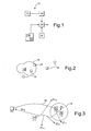
- the object determination system will initially be described with references to figure 1 , which shows a block scheme of an object awareness determination system 10 according to the invention, and figure 2 , which shows a traffic situation including a host vehicle and a set of external objects.
- the object awareness determination system 10 includes an external object sensor system 12 arranged on a host vehicle 14.
- the sensor system 12 is arranged to, within a detecting range 16 of sensor system 12, sense objects and generate input data relating to objects external 18 to the host vehicle, wherein said input data include an object position (x, y), an object velocity
- Sensor systems providing the relevant input data are commercially available and well known to persons skilled in the art. A suitable system is sold under the trade name Mobil Eye.
- the object awareness determination system 10 furthermore includes a controller 20 for determining awareness of the user to an object 22 that recently have entered the detecting range 16 of the external object sensor system.
- the controller 20 is arranged to determine awareness of the object 22 which have recently entered the detecting range 16 of the sensor system 12 based on an assessed observation of the recently entered object 18 by the user before the object has entered the detecting range 16 of said external object sensor system.
- “recently have entered the detecting range” is intended that the object has entered into the detecting range such that relevant input data concerning the object, including position and speed and optionally acceleration may be determined. In some know sensor systems these input data may be determined at entry into the detecting range, while other systems relies on a plurality of samples in order to determine speed and acceleration.
- the past trajectory should preferably be based on an observation of the external object made at its entry into the detecting range or at least based on an early set of observations made by the sensor systems. If the sensor system only may determine position, two consecutive observations will be needed in order to determine velocity and three will be needed in order to determine the acceleration of the external object.
- a suitable sampling interval for the sensor system is at least 10Hz. The position, velocity and acceleration may the be determined within approximately 0,2 seconds from entry into the detecting range. If the sensor system may detect the velocity of an object The position, velocity and acceleration may the be determined within approximately 0,1 seconds from entry into the detecting range by using a sampling rate of 10Hz
- the object awareness determination system 10 further includes an eye gaze monitor 24 arranged for determining the direction of gaze ⁇ rel of a user relative to the host vehicle.
- Eye gaze monitors 24 are well known in the art. Eye gaze monitors are used to determine the direction of gaze of the user relative to the host vehicle.
- the host vehicle yaw angle ⁇ and host vehicle position (x,y) is determined by a host vehicle movement tracker 26 arranged on the host vehicle 14.
- Host vehicle movement trackers are well known in the art.
- the host vehicle movement tracker 26 is arranged to determine past host vehicle position and past host vehicle yaw angle, preferably by use of recorded past host vehicle yaw angle and the calculation based on the model below.
- An eye gaze recorder 25 arranged for recording the direction of gaze of a user determined by the eye gaze monitor is included in the system.
- a past trajectory estimator 28 is included in the object awareness determination system.
- the past trajectory estimator 28 is arranged to, after entry of an object into the detecting range 16 of the external object sensor system 12, estimate the past trajectory of the object which has recently entered into the detecting range 16 within a time span [t- n , to] preceding a time of first entry (t 0 ) of said object into said detecting range.
- the past trajectory estimator 28 is arranged to, for each object that have recently entered the detecting range, retrieve object position (x, y), object velocity
- t -i is a set of discrete point in time before an external object has entered the detecting range 16, which set of points in time forms a time span [t -n , t -1 ].
- the time span is delimited by the end point t -n since the information available concerning the movement of the external object does not allow accurate estimation of the past position of the external object for very long time spans.
- ⁇ t is t 0 - t -i .
- the controller 20 is arranged to determine awareness of an object 22 that have recently entered into the detecting range based on an assessed observation, which observation is being assessed by use of a past host vehicle position (x,y) host,past , host vehicle yaw angle ⁇ rec , recorded direction of gaze ⁇ rel,rec of the user , and estimated past trajectory of the object (x,y) obj,est which has entered the detecting range 16 of the external object sensor system.
- the past trajectory of the host vehicle may be a recorded position given by GPS sensor, a recorded position given by a vehicle tracking system or calculated from data representing the motion of the vehicle.
- (x',y') -i;host,rec is the past position (x,y) host, past of the host vehicle at discrete pointis in time -i, T s is the sample interval; ⁇ abs,-k is the absolute host vehicle yaw angle rate at time t -k ; ⁇ -i,rec is the yaw angle at time t -i; ; (x',y') -i;host,rec is the position of the host vehicle at time t -i; ; ⁇ -k is the yaw angle at time t -k .
- a recorded host vehicle movement track 30 including recorded host vehicle position and host vehicle yaw angle is shown.
- a set of recorded direction of gaze 32 -5 - 32 -1 of the user within a time span [t -n , t 0 ] preceding a time of first entry (t 0 ) of an external object into a detecting range of the sensor system 12 arranged on the host vehicle are shown.
- a past trajectory 34 of the external object 22 estimated by the past trajectory estimator 28 for the angle is shown.
- a set of recorded directions of gaze 32 -5 - 32 -1 of the user, within a time span [t -n , t -1 ] preceding a time of first entry (t 0 ) of an external object into a detecting range, is indicated on the drawing.
- the absolute direction of gaze ⁇ abs corresponds to the direction of the external object for the recorded direction of gaze 32 -5 .
- the controller may thus determine that the driver observed the external object before entry into the detecting range of the sensor system by using recorded host vehicle position and yaw angle, recorded direction of gaze of the driver and an estimated past trajectory of the external object that recently had entered the detecting range of the sensor system.
- the controller may determine that the user is observing the object at the point of time t -i within said time span [t -n , t -1 ] preceding a time of first entry (t 0 ) if the object position is within a sector around said absolute direction of gaze at the point of time t -i .
- a relevant size of sector may be around ⁇ 2°.
- a further requirement of that the object must be within the sector during a predetermined minimum interval, which suitably may be 30ms.
- a single observation at a single point in time may also be sufficient for the purposes of this invention.
- the controller 20 is arranged to start with determining if the user is observing the object at a point of time (t -1 ) immediately preceding said time of first entry (t 0 ), and to continue with points of time t i consecutively being more distant from time of first entry (t 0 ).
- the controller may be arranged to stop the evaluation for points of times being more distant from the time of first entry (t 0 ) than a point of time t -i as soon as the controller has determined that the user is observing the object at the point of time t -i due to that the object position is determined to be within a sector around said absolute direction of gaze at the point of time t -i
- a suitable size of the time span [t -n , t 0 ] preceding a time of first entry (t 0 ) of an external object into a detecting range of the sensor system 12, during which the past trajectory of the external object is estimated is around 2 - 10 seconds, preferably around 5 seconds.
- the size of the interval may depend on the velocity of the host vehicle or of an aggregated average value of the velocities of the external objects observed by the sensor system.
Landscapes
- Engineering & Computer Science (AREA)
- Transportation (AREA)
- Mechanical Engineering (AREA)
- Physics & Mathematics (AREA)
- Automation & Control Theory (AREA)
- Mathematical Physics (AREA)
- Chemical & Material Sciences (AREA)
- Combustion & Propulsion (AREA)
- Traffic Control Systems (AREA)
Claims (26)
- Objekterkennungserfassungssystem umfassend:ein externes Objekterkennungssystem (10), das auf einem Trägerfahrzeug(14) angeordnet ist, wobei das Erfassungssystem (10) angeordnet ist, um innerhalb eines Erfassungsbereichs (16) des Erfassungssystems (10) Objekte (18) zu erkennen und Eingangsdaten, die Objekte (18) außerhalb des Trägerfahrzeuges (14) betreffen zu erzeugen, wobei die Eingangsdaten eine Objektlage (x, y), eine Objektgeschwindigkeit |(ẋ,ẏ)| und eine Richtung der Objektbewegung ((ẋ,ẏ)/|(ẋ,ẏ)|), die jedem Objekt in dem Erfassungsbereich (16) zugeordnet wird, umfassen,ein Steuergerät (20) zum Ermitteln einer Erfassung des Nutzers betreffend ein Objekt (22), das kürzlich in den Erfassungsbereich (16) des externen Objekterkennungssystems (10) eingetreten ist, wobei das Steuergerät (20) angeordnet ist, um die Erfassung des Objekts (22) basierend auf einer gewichteten Beobachtung des kürzlich eingetretenen Objekts (22) durch den Nutzer bevor das Objekt in den Erfassungsbereich (16) des externen Objekterkennungssystems (10) eingetreten ist zu erfassen, und eine Wertung durchgeführt wird, bei der eine ehemalige Blickrichtung des Fahrers mit einer ehemaligen Position des externen Objekts verglichen wird,dadurch gekennzeichnet, dass das externe Objekterkennungssystem (10) ferner einen Schätzer für den ehemaligen Kurvenverlauf (28) zum Schätzen der ehemaligen Kurve des externen Objekts aufweist.
- Objekterkennungserfassungssystem nach Anspruch 1, dadurch gekennzeichnet, dass das Objekterkennungserfassungssystem ferner umfasst
ein Augenblickrichtungskontrollgerät (24), das angeordnet ist um die Richtung des Blicks (ϕ rel ) eines Nutzers zu ermitteln,
einen Bewegungserfasser (26) des Trägerfahrzeuges, der auf dem Trägerfahrzeugangeordnet ist, wobei der Bewegungserfasser (26) des Trägerfahrzeuges angeordnet ist, um eine ehemalige Position ((x,y) host,past ) des Trägerfahrzeuges und eine ehemalige Gierrate (ϕ -i ) des Trägerfahrzeuges zu ermitteln,
ein Augenblickrichtungsaufzeichnungsgerät (25), das angeordnet ist um die Richtung des Blicks (ϕ rel;-i ) eines Nutzers, die von dem Augenblickrichtungskontrollgerät (24) ermittelt wurde, aufzuzeichnen,
einen Schätzer für ehemalige Kurvenverläufe (28), der angeordnet ist um nach dem Eintreten eines Objekts (22) in den Erfassungsbereich (16) des externen Objekterkennungssystems (10) einen ehemaligen Kurvenverlauf (28) des Objekts innerhalb einer Zeitspanne [t-n ,t -1] vor einem Zeitpunkt des ersten Eintretens (t 0) des Objekts (22) in den Erfassungsbereich (16) zu schätzen,
wobei das Steuergerät (20) zum Ermitteln der Erfassung des Objekts (22) basierend auf einer gewichteten Beobachtung angeordnet ist, wobei die Beobachtung mittels einer festgelegten ehemaligen Fahrzeugposition ((x,y) host,pasf ), der ehemaligen Gierrate des Trägerfahrzeuges (ϕ -i ), der aufgezeichneten Blickrichtung (ϕ rel,-i ) des Nutzers und des geschätzten Kurvenverlaufs (34) des Objekts (22), welches in den Erfassungsbereich (16) des externen Objekterkennungssystems (10) eingetreten ist, gewichtet wird. - Objekterkennungserfassungssystem nach Anspruch 2, dadurch gekennzeichnet, dass das Steuergerät (20) angeordnet ist, um für einen Zeitpunkt t-i innerhalb der Zeitspanne [t-n ,t -1], vor einem Zeitpunkt des ersten Eintretens (t 0) eine Objektlage (x,y)(ti ) aus dem ehemaligen Kurvenverlauf (34), eine ehemaligen Fahrzeugposition ((x,y) host,past ), und eine ehemaligen Gierrate des Trägerfahrzeuges (ϕ -i ) aus dem Bewegungserfasser (26) des Trägerfahrzeuges und eine aufgezeichnete Blickrichtung (ϕ rel,-i ) aus dem Augenblickrichtungsaufzeichnungsgerät (25) abzurufen.
- Objekterkennungserfassungssystem nach Anspruch 3, dadurch gekennzeichnet, dass das Steuergerät (20) angeordnet ist, um eine absolute Blickrichtung (ϕ abs,-i ) zu einem Zeitpunkt t-i innerhalb der Zeitspanne [t-n ,t -1] vor einem Zeitpunkt des ersten Eintretens (t 0) aus einer aufgezeichneten Blickrichtung (ϕ rel,-i ) und einer aufgezeichnete Gierrate (ϕ rel,-i ) des Trägerfahrzeuges zu einem Zeitpunkt t-i abzurufen.
- Objekterkennungserfassungssystem nach Anspruch 4, dadurch gekennzeichnet, dass das Steuergerät (20) angeordnet ist um zu ermitteln, dass der Nutzer das Objekt(22) zu dem Zeitpunkt t-i innerhalb der Zeitspanne [t-n ,t -1] vor einem Zeitpunkt des ersten Eintretens (t 0) beachtet, falls die Objektlage (x,y)(t-i ) zu dem Zeitpunkt t-i innerhalb eines Sektors um die absolute Blickrichtung (ϕ abs , -i )ist.
- Objekterkennungserfassungssystem nach Anspruch 5, dadurch gekennzeichnet, dass die Zeitdauer [t-n ,t -1] einen Satz diskreter Zeitpunkte ti {i=-n:-1} umfasst, dass der Schätzer für den ehemaligen Kurvenverlauf (28) angeordnet ist um die Objektlage (x,y)(ti ) zu den diskreten Zeitpunkten ti {i=-n:-1} zu ermitteln und dass das Steuergerät angeordnet ist, um zu ermitteln, dass der Nutzer das Objekt innerhalb der Zeitspanne [t-n ,t -1] vor einem Zeitpunkt des ersten Eintretens (t 0) beachtet, falls die Objektlage (x,y)(t-i ) innerhalb eines Sektors um die absolute Blickrichtung (ϕ abs , -i ) zu einem der diskreten Zeitpunkten ti {i=-n:-1} ist.
- Objekterkennungserfassungssystem nach Anspruch 6, dadurch gekennzeichnet, dass das Steuergerät angeordnet ist, um mit dem Ermitteln zu beginnen, falls der Nutzer das Objekt zu einem Zeitpunkt (t -1) unmittelbar vor dem Zeitpunkt des ersten Eintretens (t 0) beachtet und um mit Zeitpunkten ti fortzufahren, die fortlaufend von dem Zeitpunkt (t 0) des ersten Eintretens weiter beabstandet sind.
- Objekterkennungserfassungssystem nach Anspruch 7, dadurch gekennzeichnet, dass das Steuergerät (20) angeordnet ist, um die Auswertung der Zeitpunkte, die weiter von dem Zeitpunkt des ersten Eintretens (t 0) beabstandet sind als ein Zeitpunkt t-i zu beenden, sobald das Steuergerät ermittelt hat, dass der Nutzer das Objekt zu dem Zeitpunkt t-i aufgrund dessen, dass die Objektposition innerhalb eines Sektors um die absolute Blickrichtung zu dem Zeitpunkt t-i ist, beachtet.
- Objekterkennungserfassungssystem nach einem der vorhergehenden Ansprüche, dadurch gekennzeichnet, dass der Schätzer für den ehemaligen Kurvenverlauf (28) angeordnet ist um für jedes Objekt (22), das kürzlich in den Erfassungsbereich (16) eingetreten ist Objektposition (x, y), Objektgeschwindigkeit |(ẋ,ẏ)| und Richtung der Objektbewegung ((ẋ,ẏ)/|(ẋ,ẏ)|) zu oder nach dem Zeitpunkt des ersten Eintretens (t 0) von dem externen Objekterkennungssystem (10) abzufragen und den ehemaligen Kurvenverlauf (34) basierend auf der Objektposition (x, y), der Objektgeschwindigkeit |(ẋ,ẏ)| und der Richtung der Objektbewegung ((ẋ,ẏ)/|(ẋ,ẏ)|) zu oder nach dem Zeitpunkt des ersten Eintretens (t 0) zu ermitteln.
- Objekterkennungserfassungssystem nach Anspruch 9, dadurch gekennzeichnet, dass der Schätzer für den ehemaligen Kurvenverlauf (28) angeordnet ist, um die Objektlage (x,y)(ti ) zu einem Zeitpunkt t-i innerhalb der Zeitspanne [t-n ,t -1] vor einem Zeitpunkt des ersten Eintretens (t 0) wie folgt zu schätzen:

- Objekterkennungserfassungssystem nach einem der vorhergehenden Ansprüche, dadurch gekennzeichnet, dass die Zeitspanne [t-n ,t -1] vor einem Zeitpunkt des ersten Eintretens (t 0) mindestens 2 Sekunden unmittelbar vor dem Zeitpunkt des ersten Eintretens entspricht.
- Objekterkennungserfassungssystem nach einem der vorhergehenden Ansprüche, dadurch gekennzeichnet, dass die Zeitspanne [t-n ,t 0] vor einem Zeitpunkt des ersten Eintretens (t 0) weniger als 10 Sekunden unmittelbar vor dem Zeitpunkt des ersten Eintretens entspricht.
- Objekterkennungserfassungssystem nach einem der vorhergehenden Ansprüche, dadurch gekennzeichnet, dass die Zeitspanne [t-n ,t -1] ungefähr 5 Sekunden unmittelbar vor einem Zeitpunkt des ersten Eintretens entspricht.
- Verfahren zum Ermitteln der Erfassung eines Objekts umfassend folgende Schritte:- Verwendung eines externen Objekterkennungssystems (10), das auf einem Trägerfahrzeug (14) angeordnet ist, um innerhalb eines Erfassungsbereichs (16) des Sensorsystems Objekte (18) zu erkennen und Eingangsdaten die Objekte (18) außerhalb des Trägerfahrzeuges (14) betreffen zu erzeugen, wobei die Eingangsdaten eine Objektlage (x, y), eine Objektgeschwindigkeit |(ẋ,ẏ)| und eine Richtung der Objektbewegung ((ẋ,ẏ)/(ẋ,ẏ)|), die jedem Objekt in dem Erfassungsbereich (16) zugeordnet wird, umfassen,- Abschätzen des ehemaligen Kurvenverlaufs des externen Objekts,- Ermitteln einer Erfassung des Nutzers betreffend ein Objekt (22), das kürzlich in den Erfassungsbereich (16) des externen Objekterkennungssystems (10) eingetreten ist mittels eines Steuergeräts (20), wobei das Steuergerät (20) die Erfassung des Objekts (22) basierend auf einer gewichteten Beobachtung des kürzlich eingetretenen Objekts (22) durch den Nutzer bevor das Objekt in den Erfassungsbereich (16) des externen Objekterkennungssystems (10) eingetreten ist ermittelt, und eine Wertung durchgeführt wird, bei der eine ehemalige Blickrichtung des Fahrers mit einer ehemaligen Position des externen Objekts verglichen wird.
- Verfahren nach Anspruch 14, dadurch gekennzeichnet, dass das Verfahren ferner die Schritte aufweist:- Ermitteln der Richtung des Blicks (ϕ rel ) eines Nutzers mittels eines Augenblickrichtungskontrollgerätes (24),- Ermitteln einer ehemaligen Trägerfahrzeugposition ((x,y) host,past ) und einer ehemaligen Gierrate (ϕ -i ) des Trägerfahrzeuges mittels eines Bewegungserfassers (26) des Trägerfahrzeuges, der auf dem Trägerfahrzeug angeordnet ist,- Aufzeichnen der Blickrichtung (ϕ rel,-i ) eines Nutzers, die von dem Augenblickrichtungskontrollgerät (24) ermittelt wurde, mittels Verwendung eines Augenblickrichtungskontrollgerätes (24),- Abschätzen des ehemaligen Kurvenverlaufs (34) des Objekts (22) innerhalb einer Zeitspanne [t-n ,t -1] vor einem Zeitpunkt des ersten Eintretens (t 0) des Objekts (22) in den Erfassungsbereich (16), mittels Verwendung eines Schätzers des ehemaligen Kurvenverlaufs (28), nach dem Eintreten des Objekts (22) in den Erfassungsbereich (16) des externen Objekterkennungssystems,- wobei das Steuergerät (20) die Erfassung des Objekts (22) basierend auf einer gewichteten Beobachtung ermittelt, wobei die Beobachtung mittels einer festgelegten ehemaligen Fahrzeugposition ((x,y) host,past ), der ehemaligen Gierrate des Trägerfahrzeuges (ϕ -i ), der aufgezeichneten Blickrichtung (ϕ re/,-i ) des Nutzers und des geschätzten ehemaligen Kurvenverlaufs (34) des Objekts (22), welches in den Erfassungsbereich (16) des externen Objekterkennungssystems (10) eingetreten ist, gewichtet wird.
- Verfahren nach Anspruch 15, dadurch gekennzeichnet, dass das Steuergerät (20) für einen Zeitpunkt t-i innerhalb der Zeitspanne [t-n ,t -1] vor einem Zeitpunkt des ersten Eintretens (t 0), eine Obj ektlage (x,y)(ti ) aus dem ehemaligen Kurvenverlauf (34), einer ehemaligen Fahrzeugposition ((x,y host,past ), und einer Gierrate des Trägerfahrzeuges (ϕ -i ) aus dem Bewegungserfasser (26) des Trägerfahrzeuges und einer Blickrichtung (ϕ rel,-i ) aus dem Augenblickrichtungsaufzeichnungsgerät (25) abruft.
- Verfahren nach Anspruch 16, dadurch gekennzeichnet, dass das Steuergerät (20) eine absolute Blickrichtung (ϕ abs,-i ) zu einem Zeitpunkt t-i innerhalb der Zeitspanne [t-n ,t -1] vor einem Zeitpunkt des ersten Eintretens (t 0) von einer aufgezeichneten Blickrichtung (ϕ rel , -i ) und eine aufgezeichnete Gierrate (ϕ rel , -i ) des Trägerfahrzeuges zu dem einen Zeitpunkt t-i abruft.
- Verfahren nach Anspruch 17, dadurch gekennzeichnet, dass das Steuergerät (20) ermittelt, dass der Nutzer das Objekt(22) zu dem Zeitpunkt t-i innerhalb der Zeitspanne [t-n ,t -1] vor einem Zeitpunkt des ersten Eintretens (t 0), falls die Objektlage (x,y)(t-i ) innerhalb eines Sektors um die absolute Blickrichtung (ϕ abs,-i ) zu dem Zeitpunkt t-i ist, beachtet.
- Verfahren nach Anspruch 18, dadurch gekennzeichnet, dass die Zeitdauer [t-n ,t -1] einen Satz diskreter Zeitpunkte ti {i=-n:-1} umfasst, dass der Schätzer für den ehemaligen Kurvenverlauf (28) die Objektlage (x,y)(ti ) zu den diskreten Zeitpunkten ti {i=-n:-1} ermittelt und dass das Steuergerät (20) ermittelt, dass der Nutzer das Objekt innerhalb der Zeitspanne [t-n ,t -1] vor einem Zeitpunkt des ersten Eintretens (t 0), falls die Objektlage (x,y)(t-i ) innerhalb eines Sektors um die absolute Blickrichtung (ϕ abs,-i ) zu einem der diskreten Zeitpunkten ti {i=-n:-1} ist, beachtet.
- Verfahren nach Anspruch 19, dadurch gekennzeichnet, dass das Steuergerät mit dem Ermitteln beginnt, falls der Nutzer das Objekt zu einem Zeitpunkt (t -1) unmittelbar vor dem Zeitpunkt des ersten Eintretens (t 0) beachtet und mit Zeitpunkten t i fortfährt, die fortlaufend von dem Zeitpunkt (t 0) des ersten Eintretens weiter beabstandet sind.
- Verfahren nach Anspruch 20, dadurch gekennzeichnet, dass das Steuergerät (20) die Auswertung der Zeitpunkte, die weiter von dem Zeitpunkt des ersten Eintretens (t 0) beabstandet sind als ein Zeitpunkt t-i beendet, sobald das Steuergerät ermittelt hat, dass der Nutzer das Objekt zu dem Zeitpunkt t-i aufgrund dessen, dass die Objektposition innerhalb eines Sektors um die absolute Blickrichtung zu dem Zeitpunkt t-i ist, beachtet.
- Verfahren nach einem der Ansprüche 14 - 21, dadurch gekennzeichnet, dass der Abschätzer für den ehemaligen Kurvenverlauf (28) für jedes Objekt (22), das kürzlich in den Erfassungsbereich (16) eingetreten ist Objektposition (x,y), Objektgeschwindigkeit |(ẋ,ẏ)| und Richtung der Objektbewegung ((ẋ,ẏ)/|(ẋ,ẏ)|) zu oder nach dem Zeitpunkt des ersten Eintretens (t 0) von dem externen Objekterkennungssystem (10) abfragt und den ehemaligen Kurvenverlauf (34) basierend auf der Objektposition (x, y), der Objektgeschwindigkeit |(ẋ,ẏ)| und der Richtung der Objektbewegung ((ẋ,ẏ)/|(ẋ,ẏ)|) zu oder nach dem Zeitpunkt des ersten Eintretens (t 0) ermittelt.
- Verfahren nach Anspruch 22, dadurch gekennzeichnet, dass der Schätzer für den ehemaligen Kurvenverlauf (28) die Objektlage (x,y)(ti ) zu einem Zeitpunkt t-i innerhalb der Zeitspanne [t-n ,t 0] vor einem Zeitpunkt des ersten Eintretens (t 0) wie folgt schätzt:

- Verfahren nach Anspruch 14 - 23, dadurch gekennzeichnet, dass die Zeitspanne [t-n ,t -1] vor einem Zeitpunkt des ersten Eintretens (t 0) mindestens 2 Sekunden unmittelbar vor dem Zeitpunkt des ersten Eintretens entspricht.
- Verfahren nach Anspruch 14 - 23, dadurch gekennzeichnet, dass die Zeitspanne [t-n ,t -1] vor einem Zeitpunkt des ersten Eintretens (t 0) weniger als 10 Sekunden unmittelbar vor dem Zeitpunkt des ersten Eintretens entspricht.
- Verfahren nach Anspruch 14 - 23, dadurch gekennzeichnet, dass die Zeitspanne [t-n ,t -1] ungefähr 5 Sekunden unmittelbar vor einem Zeitpunkt des ersten Eintretens entspricht.
Priority Applications (3)
| Application Number | Priority Date | Filing Date | Title |
|---|---|---|---|
| EP06120345A EP1897773B1 (de) | 2006-09-08 | 2006-09-08 | System und Verfahren zur Bestimmung der Aufmerksamkeit auf einem Objekt |
| DE602006010380T DE602006010380D1 (de) | 2006-09-08 | 2006-09-08 | System und Verfahren zur Bestimmung der Aufmerksamkeit auf einem Objekt |
| US11/851,706 US7804413B2 (en) | 2006-09-08 | 2007-09-07 | Object awareness determination system and a method for determining awareness of an object |
Applications Claiming Priority (1)
| Application Number | Priority Date | Filing Date | Title |
|---|---|---|---|
| EP06120345A EP1897773B1 (de) | 2006-09-08 | 2006-09-08 | System und Verfahren zur Bestimmung der Aufmerksamkeit auf einem Objekt |
Publications (2)
| Publication Number | Publication Date |
|---|---|
| EP1897773A1 EP1897773A1 (de) | 2008-03-12 |
| EP1897773B1 true EP1897773B1 (de) | 2009-11-11 |
Family
ID=37691049
Family Applications (1)
| Application Number | Title | Priority Date | Filing Date |
|---|---|---|---|
| EP06120345A Active EP1897773B1 (de) | 2006-09-08 | 2006-09-08 | System und Verfahren zur Bestimmung der Aufmerksamkeit auf einem Objekt |
Country Status (3)
| Country | Link |
|---|---|
| US (1) | US7804413B2 (de) |
| EP (1) | EP1897773B1 (de) |
| DE (1) | DE602006010380D1 (de) |
Families Citing this family (11)
| Publication number | Priority date | Publication date | Assignee | Title |
|---|---|---|---|---|
| JP5354514B2 (ja) * | 2008-03-31 | 2013-11-27 | 現代自動車株式会社 | 脇見運転検出警報システム |
| EP2169500B1 (de) * | 2008-09-25 | 2012-04-04 | Volvo Car Corporation | Verfahren zur Beurteilung des Fahrzeugverlaufs in einer Straßenumgebung und Verlaufsbeurteilungssystem |
| US7991552B2 (en) * | 2008-11-06 | 2011-08-02 | Ford Global Technologies, Llc | System and method for determining a side-impact collision status of a nearby vehicle |
| US7991551B2 (en) * | 2008-11-06 | 2011-08-02 | Ford Global Technologies, Llc | System and method for determining a collision status of a nearby vehicle |
| WO2010053410A1 (en) * | 2008-11-07 | 2010-05-14 | Volvo Lastavagnar Ab | Method and system for combining sensor data |
| US8384534B2 (en) * | 2010-01-14 | 2013-02-26 | Toyota Motor Engineering & Manufacturing North America, Inc. | Combining driver and environment sensing for vehicular safety systems |
| US9601020B2 (en) * | 2010-10-05 | 2017-03-21 | Toyota Jidosha Kabushiki Kaisha | Collision determination device |
| CN104924907B (zh) * | 2015-06-19 | 2018-09-14 | 宇龙计算机通信科技(深圳)有限公司 | 一种调节车速的方法及装置 |
| US10776636B2 (en) | 2015-12-29 | 2020-09-15 | Faraday&Future Inc. | Stereo camera-based detection of objects proximate to a vehicle |
| WO2017132143A1 (en) * | 2016-01-29 | 2017-08-03 | Faraday&Future Inc. | System and method for tracking moving objects to avoid interference with vehicular door operations |
| US11365975B2 (en) * | 2018-09-27 | 2022-06-21 | Honda Motor Co., Ltd. | Visual confirmation system for driver assist system |
Family Cites Families (7)
| Publication number | Priority date | Publication date | Assignee | Title |
|---|---|---|---|---|
| JPH097100A (ja) * | 1995-06-19 | 1997-01-10 | Honda Motor Co Ltd | 運転者注視点予測装置及びこれを用いた車両用運転支援システム |
| US6659240B2 (en) * | 1999-08-10 | 2003-12-09 | Lars Dernebo | Arrangement for a piston and cylinder device |
| DE10135742A1 (de) * | 2001-07-21 | 2003-02-27 | Daimler Chrysler Ag | Kraftfahrzeug mit automatischer Blickrichtungserkennung und Verfahren zu dessen Betrieb |
| US6859144B2 (en) * | 2003-02-05 | 2005-02-22 | Delphi Technologies, Inc. | Vehicle situation alert system with eye gaze controlled alert signal generation |
| US6906619B2 (en) * | 2003-02-27 | 2005-06-14 | Motorola, Inc. | Visual attention influenced condition indicia apparatus and method |
| US6989754B2 (en) * | 2003-06-02 | 2006-01-24 | Delphi Technologies, Inc. | Target awareness determination system and method |
| JP4466299B2 (ja) * | 2004-09-28 | 2010-05-26 | 日本電気株式会社 | 車両用警報装置、車両用警報方法及び車両用警報発生プログラム |
-
2006
- 2006-09-08 EP EP06120345A patent/EP1897773B1/de active Active
- 2006-09-08 DE DE602006010380T patent/DE602006010380D1/de active Active
-
2007
- 2007-09-07 US US11/851,706 patent/US7804413B2/en active Active
Also Published As
| Publication number | Publication date |
|---|---|
| DE602006010380D1 (de) | 2009-12-24 |
| US7804413B2 (en) | 2010-09-28 |
| EP1897773A1 (de) | 2008-03-12 |
| US20080061999A1 (en) | 2008-03-13 |
Similar Documents
| Publication | Publication Date | Title |
|---|---|---|
| EP1897773B1 (de) | System und Verfahren zur Bestimmung der Aufmerksamkeit auf einem Objekt | |
| US7755473B2 (en) | Active safety system for a vehicle and a method for operation in an active safety system | |
| US8849515B2 (en) | Steering assist in driver initiated collision avoidance maneuver | |
| US8868325B2 (en) | Collision judgment apparatus for vehicle | |
| US8219299B2 (en) | Method for speed regulation of a motor vehicle in a complex traffic situation | |
| US8630793B2 (en) | Vehicle controller | |
| US20130116856A1 (en) | Method for operating a vehicle system of a motor vehicle and motor vehicle | |
| EP2046598B1 (de) | Betriebshilfsvorrichtung | |
| JP5045374B2 (ja) | 運転状態判定装置 | |
| US10192446B2 (en) | Method, system, and computer program product for detecting a possible lane change of a fellow vehicle, also a vehicle | |
| US9428057B2 (en) | Information provision device for use in vehicle | |
| US20200346644A1 (en) | Lane change intention estimation of a vehicle | |
| US7974778B2 (en) | Vehicular control object determination system and vehicular travel locus estimation system | |
| CN103782330A (zh) | 驾驶辅助装置以及驾驶辅助方法 | |
| EP1963128B1 (de) | Datenerzeugungssystem | |
| EP2492163B1 (de) | System und Verfahren zur Beurteilung der Queue-Ansteuerung | |
| US10908607B2 (en) | Enhanced traffic jam assist | |
| EP2172920B1 (de) | Bedrohungsbewertung für unerwartete Ereignisse | |
| CN111038511B (zh) | 用于adas的车辆过弯时选取目标的方法、系统和车 | |
| KR101511864B1 (ko) | 적응형 순항제어장치 및 그 제어방법 | |
| JP4234084B2 (ja) | 車両用走行軌跡推定装置 | |
| JP2006113627A (ja) | 車両用制御対象判定装置 | |
| JP6753234B2 (ja) | 運転者状態推定方法及び運転者状態推定装置 | |
| US11661070B2 (en) | Driving consciousness estimation device | |
| JP2006178674A (ja) | 走行支援装置 |
Legal Events
| Date | Code | Title | Description |
|---|---|---|---|
| PUAI | Public reference made under article 153(3) epc to a published international application that has entered the european phase |
Free format text: ORIGINAL CODE: 0009012 |
|
| AK | Designated contracting states |
Kind code of ref document: A1 Designated state(s): AT BE BG CH CY CZ DE DK EE ES FI FR GB GR HU IE IS IT LI LT LU LV MC NL PL PT RO SE SI SK TR |
|
| AX | Request for extension of the european patent |
Extension state: AL BA HR MK YU |
|
| 17P | Request for examination filed |
Effective date: 20080826 |
|
| AKX | Designation fees paid |
Designated state(s): DE GB SE |
|
| GRAP | Despatch of communication of intention to grant a patent |
Free format text: ORIGINAL CODE: EPIDOSNIGR1 |
|
| GRAS | Grant fee paid |
Free format text: ORIGINAL CODE: EPIDOSNIGR3 |
|
| GRAA | (expected) grant |
Free format text: ORIGINAL CODE: 0009210 |
|
| AK | Designated contracting states |
Kind code of ref document: B1 Designated state(s): DE GB SE |
|
| REG | Reference to a national code |
Ref country code: GB Ref legal event code: FG4D |
|
| REF | Corresponds to: |
Ref document number: 602006010380 Country of ref document: DE Date of ref document: 20091224 Kind code of ref document: P |
|
| REG | Reference to a national code |
Ref country code: SE Ref legal event code: TRGR |
|
| PLBE | No opposition filed within time limit |
Free format text: ORIGINAL CODE: 0009261 |
|
| STAA | Information on the status of an ep patent application or granted ep patent |
Free format text: STATUS: NO OPPOSITION FILED WITHIN TIME LIMIT |
|
| 26N | No opposition filed |
Effective date: 20100812 |
|
| REG | Reference to a national code |
Ref country code: GB Ref legal event code: 732E Free format text: REGISTERED BETWEEN 20111020 AND 20111025 |
|
| REG | Reference to a national code |
Ref country code: DE Ref legal event code: R082 Ref document number: 602006010380 Country of ref document: DE Representative=s name: HOFFMANN - EITLE, DE |
|
| REG | Reference to a national code |
Ref country code: DE Ref legal event code: R081 Ref document number: 602006010380 Country of ref document: DE Owner name: VOLVO CAR CORPORATION, SE Free format text: FORMER OWNER: FORD GLOBAL TECHNOLOGIES, LLC, DEARBORN, MICH., US Effective date: 20120207 Ref country code: DE Ref legal event code: R082 Ref document number: 602006010380 Country of ref document: DE Representative=s name: HOFFMANN - EITLE, DE Effective date: 20120207 Ref country code: DE Ref legal event code: R082 Ref document number: 602006010380 Country of ref document: DE Representative=s name: HOFFMANN - EITLE PATENT- UND RECHTSANWAELTE PA, DE Effective date: 20120207 |
|
| PGFP | Annual fee paid to national office [announced via postgrant information from national office to epo] |
Ref country code: SE Payment date: 20190918 Year of fee payment: 14 |
|
| PGFP | Annual fee paid to national office [announced via postgrant information from national office to epo] |
Ref country code: GB Payment date: 20190905 Year of fee payment: 14 |
|
| GBPC | Gb: european patent ceased through non-payment of renewal fee |
Effective date: 20200908 |
|
| PG25 | Lapsed in a contracting state [announced via postgrant information from national office to epo] |
Ref country code: SE Free format text: LAPSE BECAUSE OF NON-PAYMENT OF DUE FEES Effective date: 20200909 Ref country code: GB Free format text: LAPSE BECAUSE OF NON-PAYMENT OF DUE FEES Effective date: 20200908 |
|
| REG | Reference to a national code |
Ref country code: SE Ref legal event code: EUG |
|
| PGFP | Annual fee paid to national office [announced via postgrant information from national office to epo] |
Ref country code: DE Payment date: 20230822 Year of fee payment: 18 |