EP1897463A2 - Entlüftungssystem für Produktausgabesystem - Google Patents
Entlüftungssystem für Produktausgabesystem Download PDFInfo
- Publication number
- EP1897463A2 EP1897463A2 EP07115575A EP07115575A EP1897463A2 EP 1897463 A2 EP1897463 A2 EP 1897463A2 EP 07115575 A EP07115575 A EP 07115575A EP 07115575 A EP07115575 A EP 07115575A EP 1897463 A2 EP1897463 A2 EP 1897463A2
- Authority
- EP
- European Patent Office
- Prior art keywords
- piston
- seal
- product
- flange
- chamber
- Prior art date
- Legal status (The legal status is an assumption and is not a legal conclusion. Google has not performed a legal analysis and makes no representation as to the accuracy of the status listed.)
- Granted
Links
Images

Classifications
-
- A—HUMAN NECESSITIES
- A45—HAND OR TRAVELLING ARTICLES
- A45D—HAIRDRESSING OR SHAVING EQUIPMENT; EQUIPMENT FOR COSMETICS OR COSMETIC TREATMENTS, e.g. FOR MANICURING OR PEDICURING
- A45D40/00—Casings or accessories specially adapted for storing or handling solid or pasty toiletry or cosmetic substances, e.g. shaving soaps or lipsticks
- A45D40/02—Casings wherein movement of the lipstick or like solid is a sliding movement
- A45D40/04—Casings wherein movement of the lipstick or like solid is a sliding movement effected by a screw
-
- B—PERFORMING OPERATIONS; TRANSPORTING
- B05—SPRAYING OR ATOMISING IN GENERAL; APPLYING FLUENT MATERIALS TO SURFACES, IN GENERAL
- B05C—APPARATUS FOR APPLYING FLUENT MATERIALS TO SURFACES, IN GENERAL
- B05C17/00—Hand tools or apparatus using hand held tools, for applying liquids or other fluent materials to, for spreading applied liquids or other fluent materials on, or for partially removing applied liquids or other fluent materials from, surfaces
- B05C17/005—Hand tools or apparatus using hand held tools, for applying liquids or other fluent materials to, for spreading applied liquids or other fluent materials on, or for partially removing applied liquids or other fluent materials from, surfaces for discharging material from a reservoir or container located in or on the hand tool through an outlet orifice by pressure without using surface contacting members like pads or brushes
- B05C17/00576—Hand tools or apparatus using hand held tools, for applying liquids or other fluent materials to, for spreading applied liquids or other fluent materials on, or for partially removing applied liquids or other fluent materials from, surfaces for discharging material from a reservoir or container located in or on the hand tool through an outlet orifice by pressure without using surface contacting members like pads or brushes characterised by the construction of a piston as pressure exerting means, or of the co-operating container
- B05C17/00579—Hand tools or apparatus using hand held tools, for applying liquids or other fluent materials to, for spreading applied liquids or other fluent materials on, or for partially removing applied liquids or other fluent materials from, surfaces for discharging material from a reservoir or container located in or on the hand tool through an outlet orifice by pressure without using surface contacting members like pads or brushes characterised by the construction of a piston as pressure exerting means, or of the co-operating container comprising means for allowing entrapped air to escape to the atmosphere
-
- A—HUMAN NECESSITIES
- A45—HAND OR TRAVELLING ARTICLES
- A45D—HAIRDRESSING OR SHAVING EQUIPMENT; EQUIPMENT FOR COSMETICS OR COSMETIC TREATMENTS, e.g. FOR MANICURING OR PEDICURING
- A45D2200/00—Details not otherwise provided for in A45D
- A45D2200/05—Details of containers
- A45D2200/051—Airtight containers
Definitions
- This invention relates to a device for dispensing a product, such as a cosmetic product, from a housing using a piston venting system to help control the flow of the product out of the housing and to eliminate pressurization of the package during filling.
- the invention relates to a packaging and dispensing device, and particularly to a device that is suitable for the packaging of a product in a housing having an opening at one end for dispensing product.
- An operable end of the device is designed to be controlled by the user to regulate a dispensing of the product.
- the operable device can controllably move a product engaging structure to force product out of the device in an amount desired by the user.
- air can become compressed between the product and other parts of the device when the device is filled during manufacturing. That is, in the related art, an air gap can be formed between an end of the product fill and the product engaging structure designed to propel the product out of the device. The air that becomes compressed could prevent proper assembly due to buildup of pressure.
- the compressed air could prematurely force the product out of the device at an undesirable time.
- the presence of the compressed air could cause the product to dry out or otherwise reduce the performance characteristics of the product and thus, affect the quality of the product.
- dispensing devices of the related art lack proper venting and therefore difficulty in producing the device is increased and/or an unacceptable loss of the product results when dispensing the product out of the device. Unintentional loss through the dispensing holes of the device and a changing of the characteristics of the product are wasteful and can also interfere with the ability of the device to dispense a desirable amount of product to the user.
- the venting system includes at least one vent formed with a product engaging device to allow air to move in a direction substantially away from the product and out through the vent.
- the product engaging device is a piston.
- the air that passes through the vent is flowed to a vent chamber to be stored and/or discharged.
- the chamber can be a channel or groove formed around a circumference of the piston.
- the chamber is formed into a plurality of chambers and a plurality of vents is provided in fluid communication with a respective chamber of the plurality of chambers.
- a forward seal and a rear seal are provided on a portion of the piston and are configured to form and airtight seal around an edge of the vent chamber in order to contain the air that passed through the vent into the chamber.
- An example of the invention includes a piston with a flange portion formed at one end of the piston and having the at least one vent formed on the flange portion.
- the forward and rear seal are provided on the flange and engage an interior surface of the housing containing the product and the vent is formed in an area between the seals.
- a first portion of the device filled with product is mated with a second portion of the device configured to control the rate of discharge of the product, and air that is trapped in between the first portion and second portion of the device is forced to flow through a gap formed by the flange and then through the at least one vent into the chamber.
- at least one of the at least one vent is formed substantially perpendicularly to a direction of movement of the piston.
- the device according to the invention may advantageously be used for packaging and dispensing of a cosmetic or dermatological product, in the form of a liquid, soft, semi-soft, or hard product.
- the invention can provide a number of advantageous features and benefits. It is to be understood that, in practicing the invention, an embodiment can be constructed to include one or more features or benefits of embodiments disclosed herein, but not others. Accordingly, it is to be understood that the preferred embodiments discussed herein are provided as examples and are not to be construed as limiting, particularly since embodiments can be formed to practice the invention that do not include each of the features of the disclosed examples.
- the piston venting system of examples of the invention is a device for evacuation of the trapped air that has formed between various components of the dispensing device.
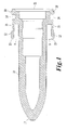
- Fig. 1 is a schematic showing a piston 10 according to an example of the invention.
- the piston 10 can be formed having a generally cylindrical cross-sectional shape with a tip end 17 and an open end 11.
- the piston can have any desirable shape such as square and oval and can be formed from any material, such as plastic.
- the open end 11 of the piston 10 can lead to a hollow interior of the piston 10 that is configured to receive, for example a driving device 25 described with respect to figures 2 and 3.
- the hollow interior of the piston 10 can extend along any length of the piston 10.
- the interior of the piston 10 can be any shape and can have any desirable cross section designed to receive the driving device 25.
- the piston 10 could be formed without a hollow interior and be configured to engage the driving device 25 at an exterior surface thereof.
- vent 15 can be formed along an outer edge of the piston 10.
- the vent 15 can be formed along a flange 13 of the piston 10.
- the flange 13 can be formed at a distance away from an outer edge of the piston 10 forming the gap 9 there between.
- the size of the gap 9 can be any size depending on the overall dimensions of the remaining features of the device according to examples of the invention.
- the flange 13 can extend around a portion of or completely around the body of the piston 10.
- a plurality of vents 15 can be formed along the flange 13 and can be any shape or size such as for example, an oval, conical, and/or square. Further, the vents 15 can be located anywhere along the length of the flange 13 as so desired. Additionally, the one or more vents 15 can be formed through the flange 13 substantially perpendicular to the movement of the piston 10 and/or flow of the product 20. However, it should be appreciated that the one or more vents 15 can be formed at any angle through the flange 13 depending on functional and/or manufacturing considerations. Accordingly, when air is forced in and around the gap 9, at least a portion of the air can escape from the gap 9 through the at least one vent 15.
- the one or more vents 15 can lead to a secondary vent chamber 14.
- the secondary chamber 14 is formed in part by a forward piston seal 12 and a rear piston seal 18, and a contour of the outer surface of the piston 10. As such, air in the gap 9 is in fluid communication with the vent chamber 14 through the at least one vent 15.
- the vent chamber 14 can be in the shape of a channel like structure that is formed around the periphery of the piston 10. Alternatively, according to examples of the invention, the vent chamber 14 can be formed only around a portion of the periphery of the piston 10 and/or can be divided up and form multiple chamber sections. Further, the one or more chambers 14 are formed to be in fluid communication with one or more of the at least one vent 15.
- vent 15 can be formed depending on the number of vents 15 created.
- the fluid communication between the gap 9, vent 15 and vent chamber 14 provides for the release of for example, the compressed air formed in the air gap 9. Accordingly, a reduction or prevention of a pressure build-up during filling of the device with a user product and/or at any other time during or after assembly of the device can be addressed or achieved.
- Fig. 2 is a schematic showing an end portion 30 for a device according to an example of the invention.
- the end portion 30 can be secured to the structure of base portion 6 or can be formed integrally there with.
- the end portion 30 can provide an end support for the base portion 6 and have a generally flat bottom surface to allow the device to be stored vertically if desired.
- a driving device 25 can be a threaded rod or similar type structure that has one end secured to or embedded in the end portion 30 and the other end configured to engage the piston 10.
- the end configured to engage the piston 10 can be a flat surface or formed with one or more protrusions or grooves. As such, it should be appreciated that the piston engaging end can have any desirable shape and/or configuration.
- the driving device 25 may be generally parallel to the housing of the base portion 6 or can be formed at an angle if so desired.
- the driving device 25 is configured to receive the threads of the end portion 30 and move upwardly and downwardly depending on the rotation of the end portion 30 controlled by the user. Due to the connection between the driving device 25 and the piston 10, as the driving device 25 is moved upwardly or downwardly a corresponding movement of the piston 10 is generated. Accordingly, the movement of the product stored in the device is controlled by the movement of the piston 10.
- Figures 3 and 4 are schematics showing a cross-sectional view of a portion of a product dispensing device created by the engagement of the housing 5 and the base assembly portion 6.
- the base assembly 6 that includes the piston 10 and end portion 30 can be engaged with the housing 5.
- one end of the driving device 25 is engaged with at least a portion of the piston 10. It should be appreciated that the driving device 25 can engage an interior portion of the piston 10 if the piston has a hollow portion, or can engage an outer end surface of the piston 10.
- the driving device 25 can include a notch or protrusion or similar type structure to engage with a notch or protrusion or similar type structure of the piston 10 to provide for a secure connection with the piston 10 or portion thereof. Accordingly, one or more embodiments of the invention provide for a rotation of the end portion 30 which translates the move to the driving device 25 and correspondingly moves the piston 10 in a desired manner.
- the operable device end portion 30 can be located at or near an end of the device in order to drive the product from the opposite end of the device and be applied to the user.
- the product dispensing device of an example of the invention can be tubular having a length with a greater dimension than a width. It should be appreciated that the device can be any size and configuration and can have a round, oval, square, rectangular, or any other desirable shape.
- a reservoir or hollow area is provided that contains the product 20 to be discharged from the device.
- the housing 5 has side walls and one end forming a tip for dispensing the product and another end having an open portion. Therefore, the consumer product 20, such as lipstick, lip gloss, cream, or any other type of cosmetic product, can be filled into at least a portion of the reservoir area of the housing 5 to be stored and contained therein.
- the product 20 can be a soft, semi-soft, hard, liquid, or other flowable product and can also be a gel, cream, or powder.
- An end piece, such as a cap or cap-like device can be placed over the tip dispensing end of the housing 5 before, during or after the product is filled into the housing in order to help contain the product in the housing.
- the product dispensing device of one or more examples of the invention is created by connecting the housing 5 and the housing of the base assembly portion 6. As the housing 5 and base portion 6 are secured together, the forward piston seal 12 will engage an interior surface of the housing 5 reducing or preventing air from escaping between the forward piston seal 12 and housing 5. Similarly, the rear piston seal 18 will slidably engage an interior surface of the housing 5 forming a seal there between. As such, creating a seal between the housing 5 and the one or more seals will force the compressed air formed from the engaging of the housing 5 and base assembly 6, to flow into the air gap 9 and out through the at least one vent 15 into the vent chamber 14. According to an example of the invention, vents can be formed in the housing 5 and/or base portion 6 to allow the air in the vent chamber 14 to escape therein.
- the secondary chamber 14 is formed in part by the forward piston seal 12 and the rear piston seal 18.
- the forward seal 12 and rear seal 18 have a first diameter that will allow the seals to engage the interior surface of the housing 5.
- the chamber 14 can be formed from a contour of the piston 10 in an area of the piston between the forward 12 and rear 18 seals.
- the contour of the chamber can be any desirable shape having a diameter smaller than a diameter of the forward 12 and rear 18 seals. That is, the outer surface of the contour should not engage the interior surface of the housing 5 in order to allow an open area into which the air can flow when forced through the vent 15.
- both the forward piston seal 12 and rear piston seal 18 are continuously engaged with the interior wall of the housing 5 after the housing 5 and base assembly portion 6 are engaged.
- the forward seal 12 can continuously form an airtight seal while the rear seal 18 slides for a set distance in the housing 5 before contacting housing vents that allow the air contained in the vent chamber 14 to be released.
- the vented piston of examples of the invention allows for assembly of the device containing the product with little or no pressurization.
- the vented piston reduces or eliminates the creation of latent product release due to the reduction of residual pressurization.
- the rear piston seal 18 may also have a single or series of slits (not shown) cut into its surface. These slits will act as a vent path for the compressed air when no housing vents are available.
- the flexibility of the rear piston seal 18 will allow the area around the slits to form back together or heal after the filling and manufacturing process is complete and pressure in the pack has decreased or been normalized. This healing process creates an airtight piston seal that allows this piston to be used with formulas containing volatiles and other elements where loss of these elements through a permanently opened vent would affect product performance and efficacy.
Landscapes
- Engineering & Computer Science (AREA)
- Mechanical Engineering (AREA)
- Containers And Packaging Bodies Having A Special Means To Remove Contents (AREA)
- Closures For Containers (AREA)
- Coating Apparatus (AREA)
Applications Claiming Priority (1)
| Application Number | Priority Date | Filing Date | Title |
|---|---|---|---|
| US11/516,625 US7874464B2 (en) | 2006-09-07 | 2006-09-07 | Venting system for a product dispensing device |
Publications (3)
| Publication Number | Publication Date |
|---|---|
| EP1897463A2 true EP1897463A2 (de) | 2008-03-12 |
| EP1897463A3 EP1897463A3 (de) | 2009-07-22 |
| EP1897463B1 EP1897463B1 (de) | 2011-11-09 |
Family
ID=38801347
Family Applications (1)
| Application Number | Title | Priority Date | Filing Date |
|---|---|---|---|
| EP07115575A Not-in-force EP1897463B1 (de) | 2006-09-07 | 2007-09-03 | Entlüftungssystem für Produktausgabesystem |
Country Status (5)
| Country | Link |
|---|---|
| US (1) | US7874464B2 (de) |
| EP (1) | EP1897463B1 (de) |
| CN (1) | CN101139025B (de) |
| AT (1) | ATE532432T1 (de) |
| ES (1) | ES2377666T3 (de) |
Families Citing this family (6)
| Publication number | Priority date | Publication date | Assignee | Title |
|---|---|---|---|---|
| GB0920768D0 (en) * | 2009-11-26 | 2010-01-13 | Rieke Corp | Dispenser pumps |
| GB201000601D0 (en) * | 2010-01-14 | 2010-03-03 | Rieke Corp | Pump dispensers |
| EP3575665B1 (de) | 2011-08-10 | 2020-10-07 | Milwaukee Electric Tool Corporation | Fettpistole |
| US8545121B2 (en) * | 2011-11-02 | 2013-10-01 | Avon Products, Inc. | Dispensing mechanism assembly |
| US9469061B2 (en) | 2013-01-30 | 2016-10-18 | Plas-Pak Industries Inc | One-piece ventable piston for a dispensing apparatus, a dispensing apparatus with same, and method of making same |
| FR3039369B1 (fr) * | 2015-07-31 | 2017-09-08 | Oreal | Procede de traitement cosmetique |
Family Cites Families (21)
| Publication number | Priority date | Publication date | Assignee | Title |
|---|---|---|---|---|
| US3227435A (en) * | 1963-04-11 | 1966-01-04 | Greer Hydraulics Inc | Resilient device |
| US3756730A (en) * | 1971-12-08 | 1973-09-04 | Spatz Corp | Fluent material dispenser having ooze prevention means |
| US4298036A (en) | 1979-12-13 | 1981-11-03 | Plastic Research Products, Inc. | Dispenser for stick solids |
| US4299238A (en) * | 1980-06-24 | 1981-11-10 | Baidwan Balinderjeet S | Vented piston and push-rod subassembly for use in a syringe barrel |
| US4700448A (en) | 1980-08-22 | 1987-10-20 | American Cyanamid Company | Process for the manufacture of a stick push-up device |
| DE3506003A1 (de) * | 1985-02-21 | 1986-08-21 | Bramlage Gmbh, 2842 Lohne | Behaelter mit auspresskolben |
| US4690154A (en) * | 1985-06-03 | 1987-09-01 | Timothy Woodford | Vented syringe |
| US4664547A (en) * | 1985-07-01 | 1987-05-12 | W. Braun Company | Product storage container and dispenser |
| US4632672A (en) * | 1985-10-07 | 1986-12-30 | Minnesota Mining And Manufacturing Company | Self venting syringe plunger |
| DE3615659A1 (de) * | 1986-05-09 | 1987-11-12 | Hilti Ag | Auspresskolben mit speicherkammer |
| US5000355A (en) | 1986-07-30 | 1991-03-19 | Beecham Inc. | Pump dispenser |
| FR2642675B1 (fr) | 1989-02-07 | 1991-05-03 | Oreal | Distributeur pour produit pateux ou solide comportant un revetement de son orifice de distribution |
| DE3938433A1 (de) | 1989-11-18 | 1991-05-23 | Alfred Von Schuckmann | Vorrichtung zur schrittweisen produkt-ausbringung |
| US5209376A (en) | 1992-03-13 | 1993-05-11 | The Procter & Gamble Company | Co-dispensing pump for fluent materials |
| US5718357A (en) | 1996-04-09 | 1998-02-17 | Courtaulds Aerospace | Industrial syringe |
| US5753212A (en) | 1996-09-16 | 1998-05-19 | The Gillette Company | Method of filling dispenser |
| US5865803A (en) * | 1997-05-19 | 1999-02-02 | Major; Miklos | Syringe device having a vented piston |
| DE20319464U1 (de) | 2002-12-10 | 2004-04-22 | Topic, Anton | Kolben für eine Kartusche zum Aufbewahren und Auspressen von pastösen Substanzen und Kartusche mit demselben |
| GB2404362B (en) * | 2003-07-29 | 2005-11-02 | Yi Li Tsai | Squeezing device for a cosmetic container |
| US7309184B2 (en) * | 2003-08-15 | 2007-12-18 | Revlon Consumer Products Corporation | Dispenser for fluid materials |
| DE202005000531U1 (de) | 2005-01-14 | 2005-08-25 | Topic, Anton | Kolben für eine Kartusche zum Aufbewahren und Auspressen von pastösen Substanzen und Kartusche mit demselben |
-
2006
- 2006-09-07 US US11/516,625 patent/US7874464B2/en not_active Expired - Fee Related
-
2007
- 2007-09-03 EP EP07115575A patent/EP1897463B1/de not_active Not-in-force
- 2007-09-03 ES ES07115575T patent/ES2377666T3/es active Active
- 2007-09-03 AT AT07115575T patent/ATE532432T1/de active
- 2007-09-07 CN CN2007101491000A patent/CN101139025B/zh not_active Expired - Fee Related
Non-Patent Citations (1)
| Title |
|---|
| None |
Also Published As
| Publication number | Publication date |
|---|---|
| CN101139025A (zh) | 2008-03-12 |
| ES2377666T3 (es) | 2012-03-29 |
| EP1897463B1 (de) | 2011-11-09 |
| CN101139025B (zh) | 2012-11-28 |
| US7874464B2 (en) | 2011-01-25 |
| EP1897463A3 (de) | 2009-07-22 |
| ATE532432T1 (de) | 2011-11-15 |
| US20080061084A1 (en) | 2008-03-13 |
Similar Documents
| Publication | Publication Date | Title |
|---|---|---|
| EP1897463A2 (de) | Entlüftungssystem für Produktausgabesystem | |
| US6415961B2 (en) | Apparatus and method for dispensing a product | |
| JP3338685B2 (ja) | 自動充填式アプリケータを有する収容塗布装置 | |
| CN1074737C (zh) | 压力作用的产品分配器及其专用阀 | |
| US20030187388A1 (en) | Multi-compartment syringe | |
| CN107636426B (zh) | 分配器及其使用方法 | |
| TWI651070B (zh) | 用於施配可流動材料之施配器 | |
| AU2006255561A1 (en) | System for storing and dispensing of a substance | |
| KR101375968B1 (ko) | 카트리지용 플런저 조립체 및 물질을 저장하기 위한 시스템 | |
| JP3267533B2 (ja) | 内容物分配用加圧装置 | |
| IL268383B2 (en) | A liquid capsule for applying on nails that includes a built-in brush | |
| KR102468588B1 (ko) | 액체 디스펜서 | |
| JP2005082246A (ja) | 空気抜き可能なピストンを備えたカートリッジ | |
| KR101533378B1 (ko) | 주사기형 화장품 용기 | |
| CN114514182A (zh) | 流体分配器 | |
| KR20090005978U (ko) | 화장퍼프를 구비한 튜브용기 | |
| CN107457107A (zh) | 流体分配装置以及用于生产这一装置的方法 | |
| EP1976765B1 (de) | Rohrabgabevorrichtung | |
| CN110167853A (zh) | 包括可移动活塞和泵系统的用于包装和分配产品的装置 | |
| WO2014086719A1 (en) | Device for packaging and application by means of a pipette | |
| CA2887868A1 (en) | Sheet-material container for a dispensing unit and method for producing a sheet-material container | |
| CN100342981C (zh) | 容器或器皿的出口装置 | |
| US20150374459A1 (en) | Method for manufacturing a cartridge for containing and meterably dispensing a flowable dental material and such a cartridge | |
| JP7297061B2 (ja) | 様々な種類のフレキシブル包装材のためのアプリケータノズル用の空気取り込みのないディスペンサ装置 | |
| JP2004315092A (ja) | ユーザーが再充填可能な真空作動ピストンを備えた液体分配容器 |
Legal Events
| Date | Code | Title | Description |
|---|---|---|---|
| PUAI | Public reference made under article 153(3) epc to a published international application that has entered the european phase |
Free format text: ORIGINAL CODE: 0009012 |
|
| 17P | Request for examination filed |
Effective date: 20070903 |
|
| AK | Designated contracting states |
Kind code of ref document: A2 Designated state(s): AT BE BG CH CY CZ DE DK EE ES FI FR GB GR HU IE IS IT LI LT LU LV MC MT NL PL PT RO SE SI SK TR |
|
| AX | Request for extension of the european patent |
Extension state: AL BA HR MK YU |
|
| PUAL | Search report despatched |
Free format text: ORIGINAL CODE: 0009013 |
|
| AK | Designated contracting states |
Kind code of ref document: A3 Designated state(s): AT BE BG CH CY CZ DE DK EE ES FI FR GB GR HU IE IS IT LI LT LU LV MC MT NL PL PT RO SE SI SK TR |
|
| AX | Request for extension of the european patent |
Extension state: AL BA HR MK RS |
|
| 17Q | First examination report despatched |
Effective date: 20090827 |
|
| AKX | Designation fees paid |
Designated state(s): AT BE BG CH CY CZ DE DK EE ES FI FR GB GR HU IE IS IT LI LT LU LV MC MT NL PL PT RO SE SI SK TR |
|
| GRAP | Despatch of communication of intention to grant a patent |
Free format text: ORIGINAL CODE: EPIDOSNIGR1 |
|
| GRAS | Grant fee paid |
Free format text: ORIGINAL CODE: EPIDOSNIGR3 |
|
| GRAA | (expected) grant |
Free format text: ORIGINAL CODE: 0009210 |
|
| AK | Designated contracting states |
Kind code of ref document: B1 Designated state(s): AT BE BG CH CY CZ DE DK EE ES FI FR GB GR HU IE IS IT LI LT LU LV MC MT NL PL PT RO SE SI SK TR |
|
| REG | Reference to a national code |
Ref country code: GB Ref legal event code: FG4D |
|
| REG | Reference to a national code |
Ref country code: CH Ref legal event code: EP |
|
| REG | Reference to a national code |
Ref country code: IE Ref legal event code: FG4D |
|
| REG | Reference to a national code |
Ref country code: DE Ref legal event code: R096 Ref document number: 602007018566 Country of ref document: DE Effective date: 20120202 |
|
| REG | Reference to a national code |
Ref country code: NL Ref legal event code: VDEP Effective date: 20111109 |
|
| REG | Reference to a national code |
Ref country code: DE Ref legal event code: R081 Ref document number: 602007018566 Country of ref document: DE Owner name: L'OREAL-D.I.P.I., FR Free format text: FORMER OWNER: L'OREAL, PARIS, FR Effective date: 20120125 |
|
| REG | Reference to a national code |
Ref country code: ES Ref legal event code: FG2A Ref document number: 2377666 Country of ref document: ES Kind code of ref document: T3 Effective date: 20120329 |
|
| LTIE | Lt: invalidation of european patent or patent extension |
Effective date: 20111109 |
|
| PG25 | Lapsed in a contracting state [announced via postgrant information from national office to epo] |
Ref country code: LT Free format text: LAPSE BECAUSE OF FAILURE TO SUBMIT A TRANSLATION OF THE DESCRIPTION OR TO PAY THE FEE WITHIN THE PRESCRIBED TIME-LIMIT Effective date: 20111109 Ref country code: IS Free format text: LAPSE BECAUSE OF FAILURE TO SUBMIT A TRANSLATION OF THE DESCRIPTION OR TO PAY THE FEE WITHIN THE PRESCRIBED TIME-LIMIT Effective date: 20120309 |
|
| PG25 | Lapsed in a contracting state [announced via postgrant information from national office to epo] |
Ref country code: SI Free format text: LAPSE BECAUSE OF FAILURE TO SUBMIT A TRANSLATION OF THE DESCRIPTION OR TO PAY THE FEE WITHIN THE PRESCRIBED TIME-LIMIT Effective date: 20111109 Ref country code: NL Free format text: LAPSE BECAUSE OF FAILURE TO SUBMIT A TRANSLATION OF THE DESCRIPTION OR TO PAY THE FEE WITHIN THE PRESCRIBED TIME-LIMIT Effective date: 20111109 Ref country code: PT Free format text: LAPSE BECAUSE OF FAILURE TO SUBMIT A TRANSLATION OF THE DESCRIPTION OR TO PAY THE FEE WITHIN THE PRESCRIBED TIME-LIMIT Effective date: 20120309 Ref country code: PL Free format text: LAPSE BECAUSE OF FAILURE TO SUBMIT A TRANSLATION OF THE DESCRIPTION OR TO PAY THE FEE WITHIN THE PRESCRIBED TIME-LIMIT Effective date: 20111109 Ref country code: GR Free format text: LAPSE BECAUSE OF FAILURE TO SUBMIT A TRANSLATION OF THE DESCRIPTION OR TO PAY THE FEE WITHIN THE PRESCRIBED TIME-LIMIT Effective date: 20120210 Ref country code: BE Free format text: LAPSE BECAUSE OF FAILURE TO SUBMIT A TRANSLATION OF THE DESCRIPTION OR TO PAY THE FEE WITHIN THE PRESCRIBED TIME-LIMIT Effective date: 20111109 Ref country code: SE Free format text: LAPSE BECAUSE OF FAILURE TO SUBMIT A TRANSLATION OF THE DESCRIPTION OR TO PAY THE FEE WITHIN THE PRESCRIBED TIME-LIMIT Effective date: 20111109 Ref country code: LV Free format text: LAPSE BECAUSE OF FAILURE TO SUBMIT A TRANSLATION OF THE DESCRIPTION OR TO PAY THE FEE WITHIN THE PRESCRIBED TIME-LIMIT Effective date: 20111109 |
|
| PG25 | Lapsed in a contracting state [announced via postgrant information from national office to epo] |
Ref country code: CY Free format text: LAPSE BECAUSE OF FAILURE TO SUBMIT A TRANSLATION OF THE DESCRIPTION OR TO PAY THE FEE WITHIN THE PRESCRIBED TIME-LIMIT Effective date: 20111109 |
|
| PG25 | Lapsed in a contracting state [announced via postgrant information from national office to epo] |
Ref country code: SK Free format text: LAPSE BECAUSE OF FAILURE TO SUBMIT A TRANSLATION OF THE DESCRIPTION OR TO PAY THE FEE WITHIN THE PRESCRIBED TIME-LIMIT Effective date: 20111109 Ref country code: BG Free format text: LAPSE BECAUSE OF FAILURE TO SUBMIT A TRANSLATION OF THE DESCRIPTION OR TO PAY THE FEE WITHIN THE PRESCRIBED TIME-LIMIT Effective date: 20120209 Ref country code: CZ Free format text: LAPSE BECAUSE OF FAILURE TO SUBMIT A TRANSLATION OF THE DESCRIPTION OR TO PAY THE FEE WITHIN THE PRESCRIBED TIME-LIMIT Effective date: 20111109 Ref country code: DK Free format text: LAPSE BECAUSE OF FAILURE TO SUBMIT A TRANSLATION OF THE DESCRIPTION OR TO PAY THE FEE WITHIN THE PRESCRIBED TIME-LIMIT Effective date: 20111109 Ref country code: EE Free format text: LAPSE BECAUSE OF FAILURE TO SUBMIT A TRANSLATION OF THE DESCRIPTION OR TO PAY THE FEE WITHIN THE PRESCRIBED TIME-LIMIT Effective date: 20111109 |
|
| PG25 | Lapsed in a contracting state [announced via postgrant information from national office to epo] |
Ref country code: RO Free format text: LAPSE BECAUSE OF FAILURE TO SUBMIT A TRANSLATION OF THE DESCRIPTION OR TO PAY THE FEE WITHIN THE PRESCRIBED TIME-LIMIT Effective date: 20111109 |
|
| PLBE | No opposition filed within time limit |
Free format text: ORIGINAL CODE: 0009261 |
|
| STAA | Information on the status of an ep patent application or granted ep patent |
Free format text: STATUS: NO OPPOSITION FILED WITHIN TIME LIMIT |
|
| REG | Reference to a national code |
Ref country code: AT Ref legal event code: MK05 Ref document number: 532432 Country of ref document: AT Kind code of ref document: T Effective date: 20111109 |
|
| 26N | No opposition filed |
Effective date: 20120810 |
|
| REG | Reference to a national code |
Ref country code: DE Ref legal event code: R097 Ref document number: 602007018566 Country of ref document: DE Effective date: 20120810 |
|
| PG25 | Lapsed in a contracting state [announced via postgrant information from national office to epo] |
Ref country code: AT Free format text: LAPSE BECAUSE OF FAILURE TO SUBMIT A TRANSLATION OF THE DESCRIPTION OR TO PAY THE FEE WITHIN THE PRESCRIBED TIME-LIMIT Effective date: 20111109 |
|
| PG25 | Lapsed in a contracting state [announced via postgrant information from national office to epo] |
Ref country code: MC Free format text: LAPSE BECAUSE OF NON-PAYMENT OF DUE FEES Effective date: 20120930 |
|
| REG | Reference to a national code |
Ref country code: CH Ref legal event code: PL |
|
| REG | Reference to a national code |
Ref country code: IE Ref legal event code: MM4A |
|
| PG25 | Lapsed in a contracting state [announced via postgrant information from national office to epo] |
Ref country code: FI Free format text: LAPSE BECAUSE OF FAILURE TO SUBMIT A TRANSLATION OF THE DESCRIPTION OR TO PAY THE FEE WITHIN THE PRESCRIBED TIME-LIMIT Effective date: 20111109 |
|
| PG25 | Lapsed in a contracting state [announced via postgrant information from national office to epo] |
Ref country code: LI Free format text: LAPSE BECAUSE OF NON-PAYMENT OF DUE FEES Effective date: 20120930 Ref country code: IE Free format text: LAPSE BECAUSE OF NON-PAYMENT OF DUE FEES Effective date: 20120903 Ref country code: CH Free format text: LAPSE BECAUSE OF NON-PAYMENT OF DUE FEES Effective date: 20120930 |
|
| PG25 | Lapsed in a contracting state [announced via postgrant information from national office to epo] |
Ref country code: MT Free format text: LAPSE BECAUSE OF FAILURE TO SUBMIT A TRANSLATION OF THE DESCRIPTION OR TO PAY THE FEE WITHIN THE PRESCRIBED TIME-LIMIT Effective date: 20111109 |
|
| PG25 | Lapsed in a contracting state [announced via postgrant information from national office to epo] |
Ref country code: TR Free format text: LAPSE BECAUSE OF FAILURE TO SUBMIT A TRANSLATION OF THE DESCRIPTION OR TO PAY THE FEE WITHIN THE PRESCRIBED TIME-LIMIT Effective date: 20111109 |
|
| PG25 | Lapsed in a contracting state [announced via postgrant information from national office to epo] |
Ref country code: LU Free format text: LAPSE BECAUSE OF NON-PAYMENT OF DUE FEES Effective date: 20120903 |
|
| PG25 | Lapsed in a contracting state [announced via postgrant information from national office to epo] |
Ref country code: HU Free format text: LAPSE BECAUSE OF FAILURE TO SUBMIT A TRANSLATION OF THE DESCRIPTION OR TO PAY THE FEE WITHIN THE PRESCRIBED TIME-LIMIT Effective date: 20070903 |
|
| REG | Reference to a national code |
Ref country code: FR Ref legal event code: PLFP Year of fee payment: 10 |
|
| REG | Reference to a national code |
Ref country code: FR Ref legal event code: PLFP Year of fee payment: 11 |
|
| REG | Reference to a national code |
Ref country code: FR Ref legal event code: PLFP Year of fee payment: 12 |
|
| PGFP | Annual fee paid to national office [announced via postgrant information from national office to epo] |
Ref country code: DE Payment date: 20190820 Year of fee payment: 13 Ref country code: FR Payment date: 20190711 Year of fee payment: 13 Ref country code: IT Payment date: 20190917 Year of fee payment: 13 |
|
| PGFP | Annual fee paid to national office [announced via postgrant information from national office to epo] |
Ref country code: GB Payment date: 20190830 Year of fee payment: 13 |
|
| PGFP | Annual fee paid to national office [announced via postgrant information from national office to epo] |
Ref country code: ES Payment date: 20191001 Year of fee payment: 13 |
|
| REG | Reference to a national code |
Ref country code: DE Ref legal event code: R119 Ref document number: 602007018566 Country of ref document: DE |
|
| GBPC | Gb: european patent ceased through non-payment of renewal fee |
Effective date: 20200903 |
|
| PG25 | Lapsed in a contracting state [announced via postgrant information from national office to epo] |
Ref country code: DE Free format text: LAPSE BECAUSE OF NON-PAYMENT OF DUE FEES Effective date: 20210401 Ref country code: FR Free format text: LAPSE BECAUSE OF NON-PAYMENT OF DUE FEES Effective date: 20200930 |
|
| PG25 | Lapsed in a contracting state [announced via postgrant information from national office to epo] |
Ref country code: GB Free format text: LAPSE BECAUSE OF NON-PAYMENT OF DUE FEES Effective date: 20200903 |
|
| PG25 | Lapsed in a contracting state [announced via postgrant information from national office to epo] |
Ref country code: IT Free format text: LAPSE BECAUSE OF NON-PAYMENT OF DUE FEES Effective date: 20200903 |
|
| REG | Reference to a national code |
Ref country code: ES Ref legal event code: FD2A Effective date: 20220114 |
|
| PG25 | Lapsed in a contracting state [announced via postgrant information from national office to epo] |
Ref country code: ES Free format text: LAPSE BECAUSE OF NON-PAYMENT OF DUE FEES Effective date: 20200904 |