EP1896353B2 - Appareil et procede de reorientation d'une pile de courrier - Google Patents
Appareil et procede de reorientation d'une pile de courrier Download PDFInfo
- Publication number
- EP1896353B2 EP1896353B2 EP06770614.3A EP06770614A EP1896353B2 EP 1896353 B2 EP1896353 B2 EP 1896353B2 EP 06770614 A EP06770614 A EP 06770614A EP 1896353 B2 EP1896353 B2 EP 1896353B2
- Authority
- EP
- European Patent Office
- Prior art keywords
- input tray
- tray
- conveyer
- mail stack
- Prior art date
- Legal status (The legal status is an assumption and is not a legal conclusion. Google has not performed a legal analysis and makes no representation as to the accuracy of the status listed.)
- Not-in-force
Links
Images


Classifications
-
- B—PERFORMING OPERATIONS; TRANSPORTING
- B65—CONVEYING; PACKING; STORING; HANDLING THIN OR FILAMENTARY MATERIAL
- B65H—HANDLING THIN OR FILAMENTARY MATERIAL, e.g. SHEETS, WEBS, CABLES
- B65H15/00—Overturning articles
- B65H15/02—Overturning piles
-
- B—PERFORMING OPERATIONS; TRANSPORTING
- B65—CONVEYING; PACKING; STORING; HANDLING THIN OR FILAMENTARY MATERIAL
- B65G—TRANSPORT OR STORAGE DEVICES, e.g. CONVEYORS FOR LOADING OR TIPPING, SHOP CONVEYOR SYSTEMS OR PNEUMATIC TUBE CONVEYORS
- B65G2207/00—Indexing codes relating to constructional details, configuration and additional features of a handling device, e.g. Conveyors
- B65G2207/46—Tray unloading features
-
- B—PERFORMING OPERATIONS; TRANSPORTING
- B65—CONVEYING; PACKING; STORING; HANDLING THIN OR FILAMENTARY MATERIAL
- B65H—HANDLING THIN OR FILAMENTARY MATERIAL, e.g. SHEETS, WEBS, CABLES
- B65H2301/00—Handling processes for sheets or webs
- B65H2301/30—Orientation, displacement, position of the handled material
- B65H2301/33—Modifying, selecting, changing orientation
- B65H2301/332—Turning, overturning
- B65H2301/3322—Turning, overturning according to a determined angle
- B65H2301/33222—90°
-
- B—PERFORMING OPERATIONS; TRANSPORTING
- B65—CONVEYING; PACKING; STORING; HANDLING THIN OR FILAMENTARY MATERIAL
- B65H—HANDLING THIN OR FILAMENTARY MATERIAL, e.g. SHEETS, WEBS, CABLES
- B65H2301/00—Handling processes for sheets or webs
- B65H2301/40—Type of handling process
- B65H2301/42—Piling, depiling, handling piles
- B65H2301/422—Handling piles, sets or stacks of articles
- B65H2301/4225—Handling piles, sets or stacks of articles in or on special supports
- B65H2301/42254—Boxes; Cassettes; Containers
Definitions
- the invention in general relates to postal delivery, and more particularly to apparatus and a method for.reorienting a stack of mail from an input tray to an output tray for delivery from a mail truck.
- An apparatus and a method for reorienting a mail stack are known e.g. from WO99/20530A .
- mail is sorted at a post office and placed horizontally in a tray.
- the tray is then placed on a shelf in a mail delivery truck next to the mail carrier.
- the mail carrier verifies the address on the top piece of mail as the carrier approaches a mail delivery point.
- the postal service has expressed a desire to have the mail in the tray oriented vertically as opposed to horizontally, to make for easier reading of addresses on the mail.
- Such mail includes conventional letters as well as flats, which is mail of a larger designated size and includes magazines and catalogs, for example.
- the present invention provides apparatus and a method to accommodate the postal service desire for vertical orientation of mail.
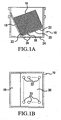
- Figs. 1 to 9 illustrate various views of one embodiment of the present invention with Fig. 1A illustrating a cut-away side view of a mail input tray and Fig. 1B illustrating a plan view.
- Figs. 10 to 17 illustrate various views of another embodiment of the present invention.
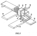
- Fig. 1 there is illustrated mail reorienting apparatus 8 having a mail input tray 10 which is delivered by an input tray feed conveyer 12 to a rotating station 14.
- the input tray 10 may optionally include an insert as illustrated in Figs. 1A and 1B , to which reference is now made.
- the insert 18 includes a sloping wall portion 19 and a sloping floor portion 20 upon which the mail stack 16 rests in a horizontal orientation with address labels facing up. With this arrangement the tops of letters and the spines of magazines, and the like, of the mail stack 16, abut the wall portion 19 to keep the stack stable.
- the floor portion 20 includes a plurality of apertures, or slots 22.
- the bottom of input tray 10. ( Fig. 1A ) includes a similar plurality of slots 24.
- the rotating station 14, rotatably by motor 25, includes a transfer deck 26 having a plurality of apertures 28 through which pusher rods 30 are extendable when moved by pusher plate 32, activated by actuator mechanism 34.
- the rotating station 14 additionally includes a frame member 40 coupled to motor 25 and which carries plate 42, moveable by actuator mechanism 44.
- An output tray 46 is delivered to location 48 of output tray take away conveyer 50, adjacent rotating station 14, by means of an output tray feed conveyer 52, while empty input trays are removed from transfer deck 26 by means of input tray take away conveyer 54.
- the empty input tray 10 is moved to the input tray take away conveyer 54 by operation of plate 56 moved by actuator mechanism 58, both of which are carried by frame 40.
- the input tray feed conveyer 12 and input tray take away conveyer 54 are perpendicular to one another, as is output tray feed conveyer 52 and output tray take away conveyer 50.
- plate 42 When plate 42 is just above the height of the mail stack as detected by a sensor such as a photo eye (not illustrated) movement of the plate 42 is stopped. This position of plate 42 helps stabilize the mail by constraining the mail between the plate 42 at the top of the mail stack, and the floor portion 20 of insert 18 ( Fig. 1 ) in input tray 10, during the rotation and transfer process to follow. In the process, plate 42 does not apply a compressive force on the mail stack. Initial rotation is illustrated in Fig. 4 .
- input tray 10 has been rotated 90° from its initial position which puts the mail stack in a vertical orientation.
- the rotation process also places the input tray 10 in the correct relationship with the output tray 46 to facilitate the transfer of mail.
- actuator mechanism 34 moves plate 32 such that rods 30 are inserted in the matching slots 24 in the bottom of input tray 10 and push on the back of the mail stack through the slots 22 in floor portion 20 of insert 18 ( Figs. 1A and 1B ).
- actuator mechanism 44 retracts plate 42 at the same rate of advancement as rods 30 such that the space between the end of the rods 30 and plate 42 remains constant so that the mail stack is loosely supported between the rods 30 and plate 42.
- the spacing and pattern of rods 30 are the same as the slots 24 in the bottom of input tray 10, however rods 30 are somewhat smaller in size than the slots 24 to accommodate for any potential misalignments.
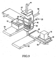
- the rods 30, constituting ejection apparatus are extended all the way, such that, as illustrated in Fig. 7 , the mail stack 16 is quickly ejected into the output tray 46. After this ejection the rotating station 14 is rotated to its initial position, as seen in Fig. 8 . Rods 30 are then retracted, as illustrated in Fig. 9 , and actuator mechanism 58 moves plate 56 to push input tray 10 onto the input tray take away conveyer 54 where it is placed in a staging area, while output tray 46, filled with vertically oriented mail, is moved to a dispatch queue. The apparatus has completed a cycle and is now ready for the next input tray, with the change in orientation process taking about 8 to 10 seconds.
- FIG. 10 to 17 Another embodiment of the present invention is illustrated in Figs. 10 to 17 .
- One difference between the embodiment of Figs. 1 to 9 and that of Figs. 10 to 17 is that in the embodiment of Figs. 1 to 9 vertical rods 30 rotate with the rotating station 14, whereas they remain horizontal in the embodiment of Figs. 10 to 17 .
- Fig. 10 illustrates mail reorienting apparatus 70 having plurality of rotating stations, with two, 72 and 74, being illustrated by way of example. Similar components at each station have been given similar reference characters. Rotating station 72 is illustrated in an upright vertical position while rotating station 74 is illustrated in a rotated horizontal orientation.
- Each rotating station 72 and 74 includes a frame 80 in which is positioned a linear actuator arrangement 82.
- the linear actuator arrangement 82 has first and second rods 84 and 85 along which a yoke assembly 86 is moveable by means of motor 88.
- Yoke assembly 86 is connected to a linear bearing 90 through which passes a rod 92 connected at its end to a plate 94 which will contact the mail stack 16, similar in operation to plate 42 of Fig. 1 .
- Frame 80 is rotated from its vertical position (72) to its horizontal position (74) by means of gears 96 and 97 connected for rotation by motor 98.
- the apparatus includes an assembly of pusher rods 100 mounted at one end to a rod mounting assembly 102 connected to a linear drive arrangement 104 which functions to move the rods 100 in a horizontal direction from a retracted position shown at station 72 to an extended position shown at station 74.
- Fig. 10 additionally illustrates the transferred mail stack 16 in an output tray 46 on an output tray take away conveyer 108.
- An empty input tray 10 on an input tray take away conveyer 110 is also shown.
- Fig. 11 illustrates the apparatus of Fig. 10 , from the opposite side.
- An output tray feed conveyer 109 may be seen in Fig. 11.
- Fig. 11 illustrates that the respective input and take away conveyers are in line, as opposed to being perpendicular to one another, as in Fig. 1 .
- Fig. 12 illustrates a single rotating station, 72 for example, from the opposite side shown in Fig. 10 .
- various drive mechanisms have not been illustrated.
- a pair of tray orientation devices 120 are provided and are secured on opposite sides of conveyer 108.
- An output tray 46 traveling along conveyer 108 is forced to the skewed angle shown when the devices 120 are encountered.
- Fig. 13 illustrates the arrangement from the opposite side.
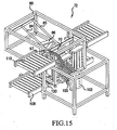
- Fig. 14 frame 80 has been rotated to a horizontal position by the gearing including gear 97. Prior to this rotation, yoke 86 was lowered such that plate 94 is positioned adjacent the top of the mail stack 16 whereupon motion is stopped by a sensor (not illustrated). The arrangement is then ready for the rods 100 to be extended through the slots in the bottom of the input tray 10. A view of the arrangement from the opposite side is illustrated in Fig. 15 .
- Fig. 16 is included to illustrate that there are actually two rotating stations 72 and 74 and that two mail reorientations may take place at the same time.
- Fig. 16 shows the two rotating stations 72 and 74 in a vertical orientation and
- Fig. 17 shows the two rotating stations after rotation to a horizontal orientation. While in the horizontal orientation the rods 100 are extended as illustrated with respect to rotating station 74 in Figs. 10 and 11 to transfer the mail stack from a horizontal orientation in input tray 10 to the desired vertical orientation in output tray 46 for delivery.
Landscapes
- Engineering & Computer Science (AREA)
- Mechanical Engineering (AREA)
- Pile Receivers (AREA)
- Sorting Of Articles (AREA)
- Devices For Checking Fares Or Tickets At Control Points (AREA)
- Data Exchanges In Wide-Area Networks (AREA)
- Attitude Control For Articles On Conveyors (AREA)
Claims (22)
- Appareil de réorientation d'une pile de courrier, comprenant :un bac d'entrée de courrier (10) ayant une pile de courrier orientée horizontalement (16) à l'intérieur de celui-ci ; ledit bac d'entrée de courrier (10) comprenant une pluralité d'ouvertures (24) au fond de celui-ci ;ledit bac d'entrée comprend un insert ayant une partie de paroi inclinée (19) et une partie de plancher inclinée (20) ; et ladite partie de plancher inclinée (20) comprend une pluralité d'ouvertures (22) dans un motif correspondant à celui dudit fond dudit bac d'entrée ;un poste de rotation (14) pour recevoir ledit bac d'entrée (10) avec ladite pile de courrier ;un bac de sortie de courrier (46) positionné adjacent au dit poste de rotation (14) ;une plaque (42) ;un mécanisme d'actionnement (44) pour placer ladite plaque (42) adjacente au sommet de ladite pile de courrier orientée horizontalement (16) pour maintenir ladite pile de courrier dans ledit bac d'entrée (10) au cours d'un processus de rotation ultérieur ;un moteur (25) couplé pour faire tourner ledit poste de rotation (14) avec ledit bac d'entrée (10), de sorte que ladite pile de courrier (16) à l'intérieur de celui-ci prenne une orientation verticale ;un appareil d'éjection (30) pour éjecter ladite pile de courrier orientée verticalement dudit bac d'entrée (10) dans ledit bac de sortie (46), ledit appareil d'éjection comprenant une pluralité de tiges poussoirs (30) qui sont déplacées à travers lesdites ouvertures dans ledit fond dudit bac d'entrée et à travers lesdites ouvertures dans ladite partie de plancher inclinée dudit insert pour être en contact avec le fond de ladite pile de courrier.
- Appareil selon la revendication 1, dans lequel :ledit poste de rotation (14) comprend un châssis (80) ;ledit mécanisme d'actionnement étant porté par ledit châssis.
- Appareil selon la revendication 1, dans lequel :ledit poste de rotation (14) comprend un pont de transfert horizontal (26) sur lequel ledit bac d'entrée est placé ;ledit pont de transfert ayant une pluralité d'ouvertures (18) à l'intérieur de celui-ci ;lesdites tiges étant orientées verticalement au-dessous desdites ouvertures dudit pont de transfert et pouvant s'étendre à travers celles-ci pour être en contact avec le fond de ladite pile de courrier ;lesdites tiges étant tournées dans une rotation horizontale à la rotation dudit poste de rotation.
- Appareil selon la revendication 1, dans lequel :les tiges (30) sont orientées horizontalement et le restent pendant la rotation dudit poste de rotation.
- Appareil selon la revendication 1, dans lequel :lesdites tiges (30) sont déplacées à une certaine vitesse pour pousser ladite pile de courrier (16) hors dudit bac d'entrée (10) ; etladite plaque (42) adjacente au sommet de ladite pile de courrier orientée horizontalement pour maintenir ladite pile de courrier dans ledit bac d'entrée est déplacée à ladite même vitesse.
- Appareil selon la revendication 1, qui comprend :un transporteur d'alimentation de bac d'entrée (12) pour fournir ledit bac d'entrée au dit poste de rotation.
- Appareil selon la revendication 6, qui comprend :un transporteur pour emporter le bac d'entrée (54).
- Appareil selon la revendication 7, dans lequel :ledit transporteur d'alimentation de bac d'entrée (12) et ledit transporteur pour emporter le bac d'entrée (54) sont perpendiculaires l'un à l'autre.
- Appareil selon la revendication 9, dans lequel :ledit poste de rotation (14) comprend un châssis (80) ;ledit poste de rotation comprend un pont de transfert horizontal sur lequel est placé ledit bac d'entrée ;ledit châssis porte un mécanisme d'éjection pour transférer ledit bac d'entrée dudit pont de transfert au dit transporteur pour emporter le bac d'entrée.
- Appareil selon la revendication 7, dans lequel :ledit transporteur d'alimentation de bac d'entrée (12) et ledit transporteur pour emporter le bac d'entrée (54) sont alignés l'un par rapport à l'autre.
- Appareil selon la revendication 1, qui comprend:un transporteur d'alimentation de bac de sortie (52) pour fournir ledit bac de sortie à ladite position adjacente au dit poste de rotation.
- Appareil selon la revendication 11, qui comprend :un transporteur pour emporter le bac de sortie (50).
- Appareil selon la revendication 12, dans lequel :ledit transporteur d'alimentation de bac de sortie (52) et ledit transporteur pour emporter le bac de sortie (50) sont perpendiculaires l'un à l'autre.
- Appareil selon la revendication 12, dans lequel :ledit transporteur d'alimentation de bac de sortie (52) et ledit transporteur pour emporter le bac de sortie (50) sont alignés l'un par rapport à l'autre.
- Appareil selon la revendication 2, dans lequel :ledit mécanisme d'actionnement (44) comprend des première et deuxième tiges ;un assemblage d'accouplement connecté aux dites tiges et pouvant être déplacé vers le haut et vers le bas desdites tiges ; et dans lequel ledit assemblage d'accouplement porte ladite plaque (42).
- Appareil selon la revendication 1, qui comprend :un transporteur d'alimentation de bac d'entrée (12) et un transporteur pour emporter le bac d'entrée (54) en alignement avec ledit transporteur d'alimentation de bac d'entrée ;un transporteur d'alimentation de bac de sortie (52) et un transporteur pour emporter le bac de sortie (50) en alignement avec ledit transporteur d'alimentation de bac de sortie ; et qui comprend une pluralité desdits postes de rotation agencés à différentes positions le long dudit transporteur d'alimentation de bac d'entrée.
- Procédé de réorientation d'une pile de courrier, comprenant les étapes consistant à :fournir un bac d'entrée de courrier (10) ayant une pile de courrier orientée horizontalement (16) ;comprenant fournir ledit bac d'entrée (10) avec une pluralité d'ouvertures au fond de celui-ci etun insert dans ledit bac d'entrée et ayant une partie de paroi inclinée et une partie de plancher inclinée avec une pluralité similaire d'ouvertures;fournir un bac de sortie de courrier (46) ;déplacer ledit bac d'entrée (10) vers un poste de rotation (14) ;fixer le sommet de ladite pile de courrier avec une plaque (42) ;faire tourner ledit poste de rotation (14) avec ledit bac d'entrée (10) au moyen d'un moteur (25) de manière à ce que ladite pile de courrier (16) prenne une orientation verticale ;éjecter ladite pile de courrier orientée verticalement dudit bac d'entrée (10) dans ledit bac de sortie; en déplaçant une pluralité de tiges à travers lesdites ouvertures au fond dudit bac d'entrée et ladite partie de plancher inclinée dudit insert pour pousser sur le fond de ladite pile de courrier ; etdéplaçant simultanément lesdites tiges et ladite plaque à la même vitesse jusqu'à ce que ladite pile de courrier soit éjectée dudit bac d'entrée;enlever le bac d'entrée (10) désormais vide ;enlever ledit bac de sortie rempli de ladite pile de courrier orientée verticalement, pour la livraison du courrier.
- Procédé selon la revendication 17, qui comprend l'étape consistant à :fournir ledit bac d'entrée au dit poste de rotation au moyen d'un transporteur d'alimentation de bac d'entrée (12).
- Procédé selon la revendication 17, qui comprend l'étape consistant à :enlever ledit bac d'entrée vide dudit poste de rotation (14) au moyen d'un transporteur pour emporter le bac d'entrée (54).
- Procédé selon la revendication 17, qui comprend l'étape consistant à :enlever ledit bac de sortie rempli de ladite pile de courrier orientée verticalement au moyen d'un transporteur pour emporter le bac de sortie (50).
- Procédé selon la revendication 17, qui comprend l'étape consistant à :faire tourner simultanément ledit bac d'entrée (10) et lesdites tiges au niveau dudit poste de rotation (14).
- Procédé selon la revendication 17, qui comprend l'étape consistant à
faire tourner uniquement ledit bac d'entrée (10) au niveau dudit poste de rotation (14) qui maintient lesdites tiges à une orientation horizontale.
Applications Claiming Priority (3)
| Application Number | Priority Date | Filing Date | Title |
|---|---|---|---|
| US68240905P | 2005-05-19 | 2005-05-19 | |
| US11/431,544 US7572094B2 (en) | 2005-05-19 | 2006-05-11 | Apparatus and method for reorienting a stack of mail |
| PCT/US2006/019346 WO2006125128A2 (fr) | 2005-05-19 | 2006-05-18 | Appareil et procede de reorientation d'une pile de courrier |
Publications (3)
| Publication Number | Publication Date |
|---|---|
| EP1896353A2 EP1896353A2 (fr) | 2008-03-12 |
| EP1896353B1 EP1896353B1 (fr) | 2010-01-06 |
| EP1896353B2 true EP1896353B2 (fr) | 2013-05-29 |
Family
ID=36992618
Family Applications (1)
| Application Number | Title | Priority Date | Filing Date |
|---|---|---|---|
| EP06770614.3A Not-in-force EP1896353B2 (fr) | 2005-05-19 | 2006-05-18 | Appareil et procede de reorientation d'une pile de courrier |
Country Status (7)
| Country | Link |
|---|---|
| US (1) | US7572094B2 (fr) |
| EP (1) | EP1896353B2 (fr) |
| AT (1) | ATE454346T1 (fr) |
| CA (1) | CA2608997A1 (fr) |
| DE (1) | DE602006011615D1 (fr) |
| ES (1) | ES2336947T5 (fr) |
| WO (1) | WO2006125128A2 (fr) |
Families Citing this family (14)
| Publication number | Priority date | Publication date | Assignee | Title |
|---|---|---|---|---|
| DE102007018634B8 (de) * | 2007-04-19 | 2008-11-27 | Siemens Ag | Vorrichtung und Verfahren zum Entladen eines Behälters |
| DE102009016559A1 (de) * | 2009-04-06 | 2010-10-07 | Siemens Aktiengesellschaft | Verfahren und Vorrichtung zum Sortieren von flachen Gegenständen |
| DE102012206779A1 (de) | 2011-05-24 | 2012-11-29 | Siemens Aktiengesellschaft | Verfahren und Vorrichtung zum Abladen eines Gegenstands auf eine Unterlage |
| US9221632B2 (en) * | 2012-03-30 | 2015-12-29 | Ncr Corporation | Media cassette loader |
| ITBO20120307A1 (it) * | 2012-06-05 | 2013-12-06 | Marchesini Group Spa | Dispositivo per l'alimentazione di una linea di ingresso di una macchina astucciatrice con astucci appiattiti contenuti all'interno di un cartone, e confezione di cartone contenente astucci appiattiti |
| DE102012219912A1 (de) | 2012-10-31 | 2014-04-30 | Siemens Aktiengesellschaft | Verfahren und Vorrichtung zur automatisierten Handhabung von Stapeln flacher Sendungen |
| CN203958774U (zh) * | 2014-06-24 | 2014-11-26 | 中邮科技有限责任公司 | 邮件摞与信盒分离设备 |
| CN105289990B (zh) * | 2014-06-24 | 2017-09-26 | 中邮科技有限责任公司 | 智能附压装置 |
| US11059185B2 (en) | 2014-10-03 | 2021-07-13 | Frito-Lay North America, Inc. | Apparatus and method for transferring a pattern from a universal surface to an ultimate package |
| US9802720B2 (en) * | 2014-10-03 | 2017-10-31 | Frito-Lay North America, Inc. | Apparatus and method for maintaining a pattern of non-rigid objects in a desired position and orientation |
| CN106904412A (zh) * | 2017-03-13 | 2017-06-30 | 卓越(苏州)自动化设备有限公司 | 自动化皮带供料机 |
| US10889440B2 (en) * | 2017-09-08 | 2021-01-12 | United States Postal Service | System for transferring articles from a container |
| US11390473B2 (en) | 2019-05-15 | 2022-07-19 | United States Postal Service | System for transferring articles from a container |
| FR3118013B1 (fr) * | 2020-12-21 | 2022-12-02 | Fives Syleps | Systeme de transfert d’articles |
Citations (2)
| Publication number | Priority date | Publication date | Assignee | Title |
|---|---|---|---|---|
| US5067303A (en) † | 1990-10-19 | 1991-11-26 | Philip Morris Incorporated | Automated box blank handling system |
| DE19827456C2 (de) † | 1998-06-19 | 2000-05-18 | Siemens Ag | Einrichtung zum Umladen von flachen Sendungen |
Family Cites Families (7)
| Publication number | Priority date | Publication date | Assignee | Title |
|---|---|---|---|---|
| US3283931A (en) * | 1964-06-08 | 1966-11-08 | Sunsweet Dryers | Apparatus for removing dried products from a support structure |
| DE3739659C1 (de) * | 1987-11-23 | 1989-03-23 | Bat Cigarettenfab Gmbh | Vorrichtung zur Zufuehrung eines Stapels von Karton-Zuschnitten zu einem Magazin |
| FR2663915B1 (fr) * | 1990-07-02 | 1993-12-31 | Cga Hbs | Dispositif de chargement d'articles sur un magasin de depilage et procede de chargement utilisant ce dispositif. |
| US5772383A (en) * | 1996-10-16 | 1998-06-30 | Bell & Howell Postal Systems Inc. | Pivotal mail tray unloader |
| DE19742367A1 (de) * | 1997-09-25 | 1999-04-01 | Siemens Ag | Verfahren und Einrichtung zum Entladen von blattförmigem Gut aus Behältern |
| WO1999020530A1 (fr) | 1997-10-22 | 1999-04-29 | Siemens Electrocom L.P. | Chargeur de plateaux |
| JP3753917B2 (ja) * | 2000-03-17 | 2006-03-08 | 茨木精機株式会社 | 包装体の整列搬出方法及びその装置 |
-
2006
- 2006-05-11 US US11/431,544 patent/US7572094B2/en active Active
- 2006-05-18 DE DE602006011615T patent/DE602006011615D1/de active Active
- 2006-05-18 WO PCT/US2006/019346 patent/WO2006125128A2/fr active Application Filing
- 2006-05-18 ES ES06770614T patent/ES2336947T5/es active Active
- 2006-05-18 AT AT06770614T patent/ATE454346T1/de not_active IP Right Cessation
- 2006-05-18 CA CA002608997A patent/CA2608997A1/fr not_active Abandoned
- 2006-05-18 EP EP06770614.3A patent/EP1896353B2/fr not_active Not-in-force
Patent Citations (2)
| Publication number | Priority date | Publication date | Assignee | Title |
|---|---|---|---|---|
| US5067303A (en) † | 1990-10-19 | 1991-11-26 | Philip Morris Incorporated | Automated box blank handling system |
| DE19827456C2 (de) † | 1998-06-19 | 2000-05-18 | Siemens Ag | Einrichtung zum Umladen von flachen Sendungen |
Also Published As
| Publication number | Publication date |
|---|---|
| ES2336947T3 (es) | 2010-04-19 |
| ES2336947T5 (es) | 2013-09-30 |
| ATE454346T1 (de) | 2010-01-15 |
| EP1896353B1 (fr) | 2010-01-06 |
| CA2608997A1 (fr) | 2006-11-23 |
| DE602006011615D1 (de) | 2010-02-25 |
| EP1896353A2 (fr) | 2008-03-12 |
| US20060267268A1 (en) | 2006-11-30 |
| WO2006125128A3 (fr) | 2007-05-31 |
| WO2006125128A2 (fr) | 2006-11-23 |
| US7572094B2 (en) | 2009-08-11 |
Similar Documents
| Publication | Publication Date | Title |
|---|---|---|
| EP1896353B2 (fr) | Appareil et procede de reorientation d'une pile de courrier | |
| RU2334668C2 (ru) | Устройство и способ изготовления упаковок для сосудов | |
| US5803704A (en) | Apparatus and method for accumulating and transferring one or more stacks of articles | |
| US20120128460A1 (en) | Apparatus and Method for Collating Products | |
| EP2366644B1 (fr) | Dispositif singulateur pour objets postaux standards et étendus | |
| US6398008B1 (en) | Aligning and conveying method of packaged article and apparatus thereof | |
| JP4824775B2 (ja) | 平坦な物体を丁合いするためおよび丁合いされた物体をさらに搬送するための装置 | |
| US9415948B1 (en) | Method for stabilizing bottles for pattern forming and related device | |
| KR102418304B1 (ko) | 캐로셀에 파우치를 공급하기 위한 장치 및 방법 | |
| US20060288661A1 (en) | Apparatus and method for loading a packaging station of an insulation batt packager | |
| US6719126B2 (en) | Device for transferring mail bins | |
| CN110092032B (zh) | 装盒机构及电芯装盒机 | |
| EP1225128A2 (fr) | Machine d'emballage | |
| CN112536222A (zh) | 一种散装药分拣包装装置 | |
| CN104394827A (zh) | 用于供应胶囊的设备 | |
| US20220332527A1 (en) | System for transferring articles from a container | |
| US11565894B2 (en) | Rotary discharge of containers from a depalletizer | |
| CN110053805B (zh) | 输送机构及电芯装盒机 | |
| CN112499091A (zh) | 全自动疫苗智能传输设备 | |
| US6182424B1 (en) | Packaging apparatus and method | |
| CN115251661B (zh) | 一种补药传输装置及传输系统 | |
| CN217626264U (zh) | 一种自动下料设备 | |
| CN208516369U (zh) | 输送装置 | |
| CN212172702U (zh) | 一种医疗试剂盒输运机构 | |
| CN218777769U (zh) | 一种药片板加料分装机构 |
Legal Events
| Date | Code | Title | Description |
|---|---|---|---|
| PUAI | Public reference made under article 153(3) epc to a published international application that has entered the european phase |
Free format text: ORIGINAL CODE: 0009012 |
|
| 17P | Request for examination filed |
Effective date: 20071204 |
|
| AK | Designated contracting states |
Kind code of ref document: A2 Designated state(s): AT BE BG CH CY CZ DE DK EE ES FI FR GB GR HU IE IS IT LI LT LU LV MC NL PL PT RO SE SI SK TR |
|
| DAX | Request for extension of the european patent (deleted) | ||
| GRAP | Despatch of communication of intention to grant a patent |
Free format text: ORIGINAL CODE: EPIDOSNIGR1 |
|
| RIN1 | Information on inventor provided before grant (corrected) |
Inventor name: SHAW, CHARLES, S. Inventor name: MISKIEWICZ, STEPHANIE, A. Inventor name: LINDHURST, JEFFREY, C. Inventor name: COWGILL, PATRICK, J. Inventor name: FEDAK, CHRISTOPHER, R. Inventor name: WAKAMIYA, STANLEY, K. |
|
| GRAS | Grant fee paid |
Free format text: ORIGINAL CODE: EPIDOSNIGR3 |
|
| GRAA | (expected) grant |
Free format text: ORIGINAL CODE: 0009210 |
|
| AK | Designated contracting states |
Kind code of ref document: B1 Designated state(s): AT BE BG CH CY CZ DE DK EE ES FI FR GB GR HU IE IS IT LI LT LU LV MC NL PL PT RO SE SI SK TR |
|
| REG | Reference to a national code |
Ref country code: GB Ref legal event code: FG4D |
|
| REG | Reference to a national code |
Ref country code: CH Ref legal event code: EP |
|
| REG | Reference to a national code |
Ref country code: IE Ref legal event code: FG4D |
|
| REF | Corresponds to: |
Ref document number: 602006011615 Country of ref document: DE Date of ref document: 20100225 Kind code of ref document: P |
|
| REG | Reference to a national code |
Ref country code: NL Ref legal event code: T3 |
|
| REG | Reference to a national code |
Ref country code: ES Ref legal event code: FG2A Ref document number: 2336947 Country of ref document: ES Kind code of ref document: T3 |
|
| PG25 | Lapsed in a contracting state [announced via postgrant information from national office to epo] |
Ref country code: SI Free format text: LAPSE BECAUSE OF FAILURE TO SUBMIT A TRANSLATION OF THE DESCRIPTION OR TO PAY THE FEE WITHIN THE PRESCRIBED TIME-LIMIT Effective date: 20100106 |
|
| LTIE | Lt: invalidation of european patent or patent extension |
Effective date: 20100106 |
|
| PG25 | Lapsed in a contracting state [announced via postgrant information from national office to epo] |
Ref country code: AT Free format text: LAPSE BECAUSE OF FAILURE TO SUBMIT A TRANSLATION OF THE DESCRIPTION OR TO PAY THE FEE WITHIN THE PRESCRIBED TIME-LIMIT Effective date: 20100106 |
|
| PG25 | Lapsed in a contracting state [announced via postgrant information from national office to epo] |
Ref country code: IS Free format text: LAPSE BECAUSE OF FAILURE TO SUBMIT A TRANSLATION OF THE DESCRIPTION OR TO PAY THE FEE WITHIN THE PRESCRIBED TIME-LIMIT Effective date: 20100506 Ref country code: LT Free format text: LAPSE BECAUSE OF FAILURE TO SUBMIT A TRANSLATION OF THE DESCRIPTION OR TO PAY THE FEE WITHIN THE PRESCRIBED TIME-LIMIT Effective date: 20100106 Ref country code: PT Free format text: LAPSE BECAUSE OF FAILURE TO SUBMIT A TRANSLATION OF THE DESCRIPTION OR TO PAY THE FEE WITHIN THE PRESCRIBED TIME-LIMIT Effective date: 20100506 |
|
| PG25 | Lapsed in a contracting state [announced via postgrant information from national office to epo] |
Ref country code: PL Free format text: LAPSE BECAUSE OF FAILURE TO SUBMIT A TRANSLATION OF THE DESCRIPTION OR TO PAY THE FEE WITHIN THE PRESCRIBED TIME-LIMIT Effective date: 20100106 Ref country code: LV Free format text: LAPSE BECAUSE OF FAILURE TO SUBMIT A TRANSLATION OF THE DESCRIPTION OR TO PAY THE FEE WITHIN THE PRESCRIBED TIME-LIMIT Effective date: 20100106 Ref country code: FI Free format text: LAPSE BECAUSE OF FAILURE TO SUBMIT A TRANSLATION OF THE DESCRIPTION OR TO PAY THE FEE WITHIN THE PRESCRIBED TIME-LIMIT Effective date: 20100106 |
|
| PLBI | Opposition filed |
Free format text: ORIGINAL CODE: 0009260 |
|
| PG25 | Lapsed in a contracting state [announced via postgrant information from national office to epo] |
Ref country code: GR Free format text: LAPSE BECAUSE OF FAILURE TO SUBMIT A TRANSLATION OF THE DESCRIPTION OR TO PAY THE FEE WITHIN THE PRESCRIBED TIME-LIMIT Effective date: 20100407 Ref country code: RO Free format text: LAPSE BECAUSE OF FAILURE TO SUBMIT A TRANSLATION OF THE DESCRIPTION OR TO PAY THE FEE WITHIN THE PRESCRIBED TIME-LIMIT Effective date: 20100106 Ref country code: SE Free format text: LAPSE BECAUSE OF FAILURE TO SUBMIT A TRANSLATION OF THE DESCRIPTION OR TO PAY THE FEE WITHIN THE PRESCRIBED TIME-LIMIT Effective date: 20100106 Ref country code: BE Free format text: LAPSE BECAUSE OF FAILURE TO SUBMIT A TRANSLATION OF THE DESCRIPTION OR TO PAY THE FEE WITHIN THE PRESCRIBED TIME-LIMIT Effective date: 20100106 Ref country code: EE Free format text: LAPSE BECAUSE OF FAILURE TO SUBMIT A TRANSLATION OF THE DESCRIPTION OR TO PAY THE FEE WITHIN THE PRESCRIBED TIME-LIMIT Effective date: 20100106 Ref country code: CY Free format text: LAPSE BECAUSE OF FAILURE TO SUBMIT A TRANSLATION OF THE DESCRIPTION OR TO PAY THE FEE WITHIN THE PRESCRIBED TIME-LIMIT Effective date: 20100106 |
|
| 26 | Opposition filed |
Opponent name: SIEMENS AG Effective date: 20100924 |
|
| PLAX | Notice of opposition and request to file observation + time limit sent |
Free format text: ORIGINAL CODE: EPIDOSNOBS2 |
|
| PG25 | Lapsed in a contracting state [announced via postgrant information from national office to epo] |
Ref country code: SK Free format text: LAPSE BECAUSE OF FAILURE TO SUBMIT A TRANSLATION OF THE DESCRIPTION OR TO PAY THE FEE WITHIN THE PRESCRIBED TIME-LIMIT Effective date: 20100106 Ref country code: BG Free format text: LAPSE BECAUSE OF FAILURE TO SUBMIT A TRANSLATION OF THE DESCRIPTION OR TO PAY THE FEE WITHIN THE PRESCRIBED TIME-LIMIT Effective date: 20100406 Ref country code: CZ Free format text: LAPSE BECAUSE OF FAILURE TO SUBMIT A TRANSLATION OF THE DESCRIPTION OR TO PAY THE FEE WITHIN THE PRESCRIBED TIME-LIMIT Effective date: 20100106 |
|
| PG25 | Lapsed in a contracting state [announced via postgrant information from national office to epo] |
Ref country code: MC Free format text: LAPSE BECAUSE OF NON-PAYMENT OF DUE FEES Effective date: 20100531 |
|
| REG | Reference to a national code |
Ref country code: CH Ref legal event code: PL |
|
| PG25 | Lapsed in a contracting state [announced via postgrant information from national office to epo] |
Ref country code: DK Free format text: LAPSE BECAUSE OF FAILURE TO SUBMIT A TRANSLATION OF THE DESCRIPTION OR TO PAY THE FEE WITHIN THE PRESCRIBED TIME-LIMIT Effective date: 20100106 |
|
| PG25 | Lapsed in a contracting state [announced via postgrant information from national office to epo] |
Ref country code: LI Free format text: LAPSE BECAUSE OF NON-PAYMENT OF DUE FEES Effective date: 20100531 Ref country code: CH Free format text: LAPSE BECAUSE OF NON-PAYMENT OF DUE FEES Effective date: 20100531 |
|
| PLAF | Information modified related to communication of a notice of opposition and request to file observations + time limit |
Free format text: ORIGINAL CODE: EPIDOSCOBS2 |
|
| REG | Reference to a national code |
Ref country code: NL Ref legal event code: SD Effective date: 20110224 |
|
| PG25 | Lapsed in a contracting state [announced via postgrant information from national office to epo] |
Ref country code: IT Free format text: LAPSE BECAUSE OF FAILURE TO SUBMIT A TRANSLATION OF THE DESCRIPTION OR TO PAY THE FEE WITHIN THE PRESCRIBED TIME-LIMIT Effective date: 20100106 |
|
| PG25 | Lapsed in a contracting state [announced via postgrant information from national office to epo] |
Ref country code: IE Free format text: LAPSE BECAUSE OF NON-PAYMENT OF DUE FEES Effective date: 20100518 |
|
| PLBB | Reply of patent proprietor to notice(s) of opposition received |
Free format text: ORIGINAL CODE: EPIDOSNOBS3 |
|
| REG | Reference to a national code |
Ref country code: GB Ref legal event code: 732E Free format text: REGISTERED BETWEEN 20110428 AND 20110504 |
|
| REG | Reference to a national code |
Ref country code: ES Ref legal event code: PC2A Owner name: NORTHROP GRUMMAN SYSTEMS CORPORATION Effective date: 20110613 |
|
| PG25 | Lapsed in a contracting state [announced via postgrant information from national office to epo] |
Ref country code: HU Free format text: LAPSE BECAUSE OF FAILURE TO SUBMIT A TRANSLATION OF THE DESCRIPTION OR TO PAY THE FEE WITHIN THE PRESCRIBED TIME-LIMIT Effective date: 20100707 Ref country code: LU Free format text: LAPSE BECAUSE OF NON-PAYMENT OF DUE FEES Effective date: 20100518 |
|
| PG25 | Lapsed in a contracting state [announced via postgrant information from national office to epo] |
Ref country code: TR Free format text: LAPSE BECAUSE OF FAILURE TO SUBMIT A TRANSLATION OF THE DESCRIPTION OR TO PAY THE FEE WITHIN THE PRESCRIBED TIME-LIMIT Effective date: 20100106 |
|
| REG | Reference to a national code |
Ref country code: DE Ref legal event code: R081 Ref document number: 602006011615 Country of ref document: DE Owner name: NORTHROP GRUMMAN SYSTEMS CORPORATION (N.D.GES., US Free format text: FORMER OWNER: NORTHROP GRUMMAN CORP., LOS ANGELES, US Effective date: 20130205 Ref country code: DE Ref legal event code: R081 Ref document number: 602006011615 Country of ref document: DE Owner name: NORTHROP GRUMMAN SYSTEMS CORPORATION (N.D.GES., US Free format text: FORMER OWNER: NORTHROP GRUMMAN CORP., LOS ANGELES, CALIF., US Effective date: 20130205 |
|
| PUAH | Patent maintained in amended form |
Free format text: ORIGINAL CODE: 0009272 |
|
| STAA | Information on the status of an ep patent application or granted ep patent |
Free format text: STATUS: PATENT MAINTAINED AS AMENDED |
|
| 27A | Patent maintained in amended form |
Effective date: 20130529 |
|
| AK | Designated contracting states |
Kind code of ref document: B2 Designated state(s): AT BE BG CH CY CZ DE DK EE ES FI FR GB GR HU IE IS IT LI LT LU LV MC NL PL PT RO SE SI SK TR |
|
| REG | Reference to a national code |
Ref country code: DE Ref legal event code: R102 Ref document number: 602006011615 Country of ref document: DE Effective date: 20130529 |
|
| REG | Reference to a national code |
Ref country code: ES Ref legal event code: DC2A Ref document number: 2336947 Country of ref document: ES Kind code of ref document: T5 Effective date: 20130930 |
|
| REG | Reference to a national code |
Ref country code: NL Ref legal event code: T3 |
|
| PG25 | Lapsed in a contracting state [announced via postgrant information from national office to epo] |
Ref country code: LV Free format text: LAPSE BECAUSE OF FAILURE TO SUBMIT A TRANSLATION OF THE DESCRIPTION OR TO PAY THE FEE WITHIN THE PRESCRIBED TIME-LIMIT Effective date: 20130529 |
|
| REG | Reference to a national code |
Ref country code: FR Ref legal event code: PLFP Year of fee payment: 11 |
|
| REG | Reference to a national code |
Ref country code: FR Ref legal event code: PLFP Year of fee payment: 12 |
|
| REG | Reference to a national code |
Ref country code: FR Ref legal event code: PLFP Year of fee payment: 13 |
|
| PGFP | Annual fee paid to national office [announced via postgrant information from national office to epo] |
Ref country code: ES Payment date: 20180626 Year of fee payment: 13 Ref country code: DE Payment date: 20180522 Year of fee payment: 13 |
|
| PGFP | Annual fee paid to national office [announced via postgrant information from national office to epo] |
Ref country code: NL Payment date: 20180518 Year of fee payment: 13 Ref country code: FR Payment date: 20180522 Year of fee payment: 13 |
|
| PGFP | Annual fee paid to national office [announced via postgrant information from national office to epo] |
Ref country code: GB Payment date: 20180518 Year of fee payment: 13 |
|
| REG | Reference to a national code |
Ref country code: DE Ref legal event code: R119 Ref document number: 602006011615 Country of ref document: DE |
|
| REG | Reference to a national code |
Ref country code: NL Ref legal event code: MM Effective date: 20190601 |
|
| GBPC | Gb: european patent ceased through non-payment of renewal fee |
Effective date: 20190518 |
|
| PG25 | Lapsed in a contracting state [announced via postgrant information from national office to epo] |
Ref country code: NL Free format text: LAPSE BECAUSE OF NON-PAYMENT OF DUE FEES Effective date: 20190601 Ref country code: DE Free format text: LAPSE BECAUSE OF NON-PAYMENT OF DUE FEES Effective date: 20191203 Ref country code: GB Free format text: LAPSE BECAUSE OF NON-PAYMENT OF DUE FEES Effective date: 20190518 |
|
| PG25 | Lapsed in a contracting state [announced via postgrant information from national office to epo] |
Ref country code: FR Free format text: LAPSE BECAUSE OF NON-PAYMENT OF DUE FEES Effective date: 20190531 |
|
| REG | Reference to a national code |
Ref country code: ES Ref legal event code: FD2A Effective date: 20201001 |
|
| PG25 | Lapsed in a contracting state [announced via postgrant information from national office to epo] |
Ref country code: ES Free format text: LAPSE BECAUSE OF NON-PAYMENT OF DUE FEES Effective date: 20190519 |