EP1896105B1 - Catheter-based, dual coil photopolymerization system - Google Patents
Catheter-based, dual coil photopolymerization system Download PDFInfo
- Publication number
- EP1896105B1 EP1896105B1 EP06748314A EP06748314A EP1896105B1 EP 1896105 B1 EP1896105 B1 EP 1896105B1 EP 06748314 A EP06748314 A EP 06748314A EP 06748314 A EP06748314 A EP 06748314A EP 1896105 B1 EP1896105 B1 EP 1896105B1
- Authority
- EP
- European Patent Office
- Prior art keywords
- catheter
- coil
- fluid
- channeling structure
- fluid channeling
- Prior art date
- Legal status (The legal status is an assumption and is not a legal conclusion. Google has not performed a legal analysis and makes no representation as to the accuracy of the status listed.)
- Expired - Lifetime
Links
Images


Classifications
-
- A—HUMAN NECESSITIES
- A61—MEDICAL OR VETERINARY SCIENCE; HYGIENE
- A61L—METHODS OR APPARATUS FOR STERILISING MATERIALS OR OBJECTS IN GENERAL; DISINFECTION, STERILISATION OR DEODORISATION OF AIR; CHEMICAL ASPECTS OF BANDAGES, DRESSINGS, ABSORBENT PADS OR SURGICAL ARTICLES; MATERIALS FOR BANDAGES, DRESSINGS, ABSORBENT PADS OR SURGICAL ARTICLES
- A61L31/00—Materials for other surgical articles, e.g. stents, stent-grafts, shunts, surgical drapes, guide wires, materials for adhesion prevention, occluding devices, surgical gloves, tissue fixation devices
- A61L31/08—Materials for coatings
- A61L31/10—Macromolecular materials
-
- A—HUMAN NECESSITIES
- A61—MEDICAL OR VETERINARY SCIENCE; HYGIENE
- A61L—METHODS OR APPARATUS FOR STERILISING MATERIALS OR OBJECTS IN GENERAL; DISINFECTION, STERILISATION OR DEODORISATION OF AIR; CHEMICAL ASPECTS OF BANDAGES, DRESSINGS, ABSORBENT PADS OR SURGICAL ARTICLES; MATERIALS FOR BANDAGES, DRESSINGS, ABSORBENT PADS OR SURGICAL ARTICLES
- A61L24/00—Surgical adhesives or cements; Adhesives for colostomy devices
- A61L24/001—Use of materials characterised by their function or physical properties
- A61L24/0031—Hydrogels or hydrocolloids
-
- A—HUMAN NECESSITIES
- A61—MEDICAL OR VETERINARY SCIENCE; HYGIENE
- A61L—METHODS OR APPARATUS FOR STERILISING MATERIALS OR OBJECTS IN GENERAL; DISINFECTION, STERILISATION OR DEODORISATION OF AIR; CHEMICAL ASPECTS OF BANDAGES, DRESSINGS, ABSORBENT PADS OR SURGICAL ARTICLES; MATERIALS FOR BANDAGES, DRESSINGS, ABSORBENT PADS OR SURGICAL ARTICLES
- A61L27/00—Materials for grafts or prostheses or for coating grafts or prostheses
- A61L27/28—Materials for coating prostheses
- A61L27/34—Macromolecular materials
-
- A—HUMAN NECESSITIES
- A61—MEDICAL OR VETERINARY SCIENCE; HYGIENE
- A61L—METHODS OR APPARATUS FOR STERILISING MATERIALS OR OBJECTS IN GENERAL; DISINFECTION, STERILISATION OR DEODORISATION OF AIR; CHEMICAL ASPECTS OF BANDAGES, DRESSINGS, ABSORBENT PADS OR SURGICAL ARTICLES; MATERIALS FOR BANDAGES, DRESSINGS, ABSORBENT PADS OR SURGICAL ARTICLES
- A61L29/00—Materials for catheters, medical tubing, cannulae, or endoscopes or for coating catheters
- A61L29/08—Materials for coatings
- A61L29/085—Macromolecular materials
-
- A—HUMAN NECESSITIES
- A61—MEDICAL OR VETERINARY SCIENCE; HYGIENE
- A61M—DEVICES FOR INTRODUCING MEDIA INTO, OR ONTO, THE BODY; DEVICES FOR TRANSDUCING BODY MEDIA OR FOR TAKING MEDIA FROM THE BODY; DEVICES FOR PRODUCING OR ENDING SLEEP OR STUPOR
- A61M25/00—Catheters; Hollow probes
- A61M25/0043—Catheters; Hollow probes characterised by structural features
- A61M25/0045—Catheters; Hollow probes characterised by structural features multi-layered, e.g. coated
-
- A—HUMAN NECESSITIES
- A61—MEDICAL OR VETERINARY SCIENCE; HYGIENE
- A61M—DEVICES FOR INTRODUCING MEDIA INTO, OR ONTO, THE BODY; DEVICES FOR TRANSDUCING BODY MEDIA OR FOR TAKING MEDIA FROM THE BODY; DEVICES FOR PRODUCING OR ENDING SLEEP OR STUPOR
- A61M31/00—Devices for introducing or retaining media, e.g. remedies, in cavities of the body
-
- A—HUMAN NECESSITIES
- A61—MEDICAL OR VETERINARY SCIENCE; HYGIENE
- A61M—DEVICES FOR INTRODUCING MEDIA INTO, OR ONTO, THE BODY; DEVICES FOR TRANSDUCING BODY MEDIA OR FOR TAKING MEDIA FROM THE BODY; DEVICES FOR PRODUCING OR ENDING SLEEP OR STUPOR
- A61M25/00—Catheters; Hollow probes
- A61M25/0021—Catheters; Hollow probes characterised by the form of the tubing
- A61M25/0023—Catheters; Hollow probes characterised by the form of the tubing by the form of the lumen, e.g. cross-section, variable diameter
- A61M25/0026—Multi-lumen catheters with stationary elements
- A61M2025/0034—Multi-lumen catheters with stationary elements characterized by elements which are assembled, connected or fused, e.g. splittable tubes, outer sheaths creating lumina or separate cores
-
- A—HUMAN NECESSITIES
- A61—MEDICAL OR VETERINARY SCIENCE; HYGIENE
- A61M—DEVICES FOR INTRODUCING MEDIA INTO, OR ONTO, THE BODY; DEVICES FOR TRANSDUCING BODY MEDIA OR FOR TAKING MEDIA FROM THE BODY; DEVICES FOR PRODUCING OR ENDING SLEEP OR STUPOR
- A61M25/00—Catheters; Hollow probes
- A61M25/0021—Catheters; Hollow probes characterised by the form of the tubing
- A61M25/0023—Catheters; Hollow probes characterised by the form of the tubing by the form of the lumen, e.g. cross-section, variable diameter
- A61M25/0026—Multi-lumen catheters with stationary elements
- A61M2025/0037—Multi-lumen catheters with stationary elements characterized by lumina being arranged side-by-side
-
- A—HUMAN NECESSITIES
- A61—MEDICAL OR VETERINARY SCIENCE; HYGIENE
- A61M—DEVICES FOR INTRODUCING MEDIA INTO, OR ONTO, THE BODY; DEVICES FOR TRANSDUCING BODY MEDIA OR FOR TAKING MEDIA FROM THE BODY; DEVICES FOR PRODUCING OR ENDING SLEEP OR STUPOR
- A61M25/00—Catheters; Hollow probes
- A61M25/0021—Catheters; Hollow probes characterised by the form of the tubing
- A61M25/0023—Catheters; Hollow probes characterised by the form of the tubing by the form of the lumen, e.g. cross-section, variable diameter
- A61M25/0026—Multi-lumen catheters with stationary elements
- A61M25/0029—Multi-lumen catheters with stationary elements characterized by features relating to least one lumen located at the middle part of the catheter, e.g. slots, flaps, valves, cuffs, apertures, notches, grooves or rapid exchange ports
-
- Y—GENERAL TAGGING OF NEW TECHNOLOGICAL DEVELOPMENTS; GENERAL TAGGING OF CROSS-SECTIONAL TECHNOLOGIES SPANNING OVER SEVERAL SECTIONS OF THE IPC; TECHNICAL SUBJECTS COVERED BY FORMER USPC CROSS-REFERENCE ART COLLECTIONS [XRACs] AND DIGESTS
- Y10—TECHNICAL SUBJECTS COVERED BY FORMER USPC
- Y10T—TECHNICAL SUBJECTS COVERED BY FORMER US CLASSIFICATION
- Y10T29/00—Metal working
- Y10T29/49—Method of mechanical manufacture
- Y10T29/49826—Assembling or joining
Definitions
- This invention relates generally to biomedical systems for treating vascular conditions. More specifically, the invention relates to a catheter-based, dual coil photopolymerization system.
- Photopolymerization i.e., polymerization induced by light
- photopolymerization induced by light is used to convert a liquid monomer or macromer to a polymer using visible or ultraviolet radiation.
- Some types of cross-linked hydrophilic polymers known as hydrogels may be formed in vivo using photopolymerization. These hydrogels exhibit good biocompatibility, making them attractive materials for use in a variety of biomedical applications.
- Formation of photopolymerized hydrogels in vivo can be accomplished using bulk or interfacial photopolymerization.
- a photoinitiator is dissolved in a hydrogel precursor (prepolymer) solution.
- a photoinitiator is a material that has a high absorption at a specific wavelength of light to produce radical initiating species that convert a prepolymer to a polymer.
- the hydrogel precursor and photoinitiator solution is converted to the hydrogel state.
- a photoinitiator is adsorbed onto the surface of tissues or cells. Eosin photoinitiators are commonly used because of their high affinity for tissues.
- a prepolymer in this case a hydrogel precursor solution, is then delivered to the site, and the site is exposed to an appropriate light source. Polymerization occurs at the tissue interface, where the hydrogel precursor is in contact with the adsorbed photoinitiator.
- Interfacial photopolymerization may be used to form thin hydrogel linings on various tissue surfaces, including the inner walls of vessels carrying bodily fluids.
- Dual occlusion catheters are currently used to deliver photoinitiators and prepolymers to target vessels.
- the treatment cavity formed between the two balloons must be filled with each component, requiring a relatively large amount of material. For example, typically about 3 milliliters of a prepolymer is required to fill the cavity, even though only a fraction of the material is converted into a hydrogel coating on the wall of the vessel.
- complications can occur if the vessel is occluded for more than 60 seconds. This may require the clinician performing the procedure to rush in order to avoid damage to the vessel and other complications when using a dual occlusion catheter.
- a device according to the preamble of claim 1 is known from the document US-A-5951539 .
- One aspect of the present invention is a system for treating a vascular condition.
- the system comprises an outer catheter, an inner catheter, and a fluid channeling structure.
- a proximal portion of the inner catheter is slidably received within the outer catheter to form a catheter assembly.
- the fluid channeling structure is mounted on the catheter assembly with a proximal portion of the structure affixed to a distal portion of the outer catheter and a distal portion of the structure affixed to a distal portion of the inner catheter.
- the fluid channeling structure comprises an elastic coil, an elastomeric sleeve, and a light emission coil that has a diameter smaller than that of the elastic coil.
- the elastic coil is received within the elastomeric sleeve, and the elastomeric sleeve is received within the light emission coil. Loops of the light emission coil are interspaced with loops of the elastic coil.
- a catheter assembly is formed by positioning a proximal portion of an inner catheter within a lumen of an outer catheter.
- a fluid channeling structure is formed by positioning an elastic coil within an elastomeric sleeve and then coiling an optical fiber about the elastomeric sleeve.
- a distal portion of the catheter assembly is positioned within the fluid channeling structure.
- a proximal portion of the fluid channeling structure is attached to a distal portion of the outer catheter.
- a distal portion of the fluid channeling structure is attached to a distal portion of the inner catheter.
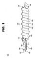
- System 100 comprises an inner catheter, guidewire catheter 110; an outer catheter, pullback catheter 120; a fluid channeling structure 130; a fluid delivery catheter 140; and a guidewire 150.
- Guidewire catheter 110 and pullback catheter 120 combine to form a catheter assembly 115.
- Fluid channeling structure 130 includes an elastic coil 132, an elastomeric sleeve 134, and a light emission coil 136.
- FIG. 1 shows fluid channeling structure 130 as it would appear when expanded at a treatment site within a vessel.
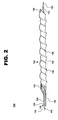
- FIG. 2 shows fluid channeling structure 130 extended longitudinally to provide a narrowed crossing profile for delivery of system 100 to a target treatment area within a vessel.
- guidewire catheter 110 is a stainless steel hypotube.
- Other catheters may be used, including, but not limited to, catheters formed using nitinol, polyurethane, polytetrafluoroethylene (PTFE), polyethylene, and nylon.
- a distal portion of guidewire catheter 110 is spiral cut to provide increased flexibility.
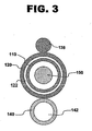
- a proximal portion of guidewire catheter 110 is slidably received within central lumen 122 (shown in FIG. 3 ) of pullback catheter 120. Together, guidewire catheter 110 and pullback catheter 120 form catheter assembly 115.
- Pullback catheter 120 comprises one or more biocompatible materials, including, but not limited to, polyurethane, polytetrafluoroethylene (PTFE), polyethylene, nylon, nitinol, and stainless steel.
- the distal tip of pullback catheter 120 may be necked down or thermally formed to reduce the diameter of the tip to create a partial seal with guidewire catheter 110.
- the partial seal minimizes blood flow between the pullback catheter and the guidewire catheter, as well as improves tractability, by reducing the gap between the two catheters.
- Pullback catheter 120 is so called because it is used to pull back on fluid channeling structure 130 to longitudinally extend the structure, thereby reducing the crossing profile of the fluid channeling structure for delivery to and withdrawal from a target treatment area within a vessel.
- Fluid channeling structure 130 comprises elastic coil 132, elastomeric sleeve 134, and light emission coil 136.
- elastic coil 132 is a nitinol coil.
- the elastic coil may be formed using another elastic material capable of being preset into a coiled configuration that is not significantly deformed by alternately stretching and compressing the coil. That is, the spacing between loops of elastic coil 132 remains substantially uniform whether the coil is stretched or compressed, and the coil is capable of self expanding into a deployment configuration having a predetermined diameter.
- Such materials include, but are not limited to, another nickel-titanium alloy, a nickel-cobalt alloy, another cobalt alloy, a thermoset plastic, stainless steel, a suitable biocompatible shape-memory material, a suitable biocompatible superelastic material, combinations thereof, and the like.
- Elastic coil 132 (shown in phantom) is received within elastomeric sleeve 134.
- Elastomeric sleeve 134 is formed using one or more appropriate biocompatible materials.
- system 100 is used to apply a polymer coating (typically a hydrogel) to the inner surface of a vessel by interfacial photopolymerization using a photoinitiator. Therefore, the composition of elastomeric sleeve 134 is determined based on the polymer coating to be applied, with a composition chosen that does not absorb or otherwise retain the photoinitiator and that will not adhere to the coating material following photopolymerization of the prepolymer.
- a polymer coating typically a hydrogel
- elastomeric sleeve 134 may comprise a silicon or thermoplastic elastomer such as polyurethane.
- PEG polyethylene glycol
- elastomeric sleeve 134 may comprise a silicon or thermoplastic elastomer such as polyurethane.
- prepolymer is used herein to refer to any monomer, macromer, or polymer that is converted by photopolymerization in the presence of a photoinitiator to a polymer coating.
- Elastomeric sleeve 134 is received within light emission coil 136.
- light emission coil 136 is formed into a distal portion of an optical fiber. This distal portion of the fiber is abraded to diffuse light from the coil.
- a proximal portion of the fiber, indicated at 138 in FIG. 1 is substantially straight and extends along the length of pullback catheter 120, terminating at a connecter arm of a luer (not shown).
- Light emission coil 136 is operably connected to a light source via proximal portion 138.
- light emission coil 136 may be a section of optical fiber that is treated in another manner to diffuse light from the fiber.
- light emission coil 136 may be any material capable of emitting the desired intensity of light and may be operably connected to a light source by any means of conveying light to the coil.
- light emission coil 136 may be reinforced with a material such as nitinol or may comprise a glass/graphite reinforced plastic composite coil.
- Light emission coil 136 is smaller in diameter than elastic coil 132.
- elastic coil 132 has a 3-millimeter outer diameter
- light emission coil 136 will have an outer diameter between 2.5 and 2.75 millimeters.
- loops of light emission coil 134 are interspaced with (i.e., positioned between) loops of elastic coil 132 and constrict elastomeric sleeve 134 within the loops of elastic coil 132 such that a helical channel 135 is formed in the sleeve when fluid channeling structure 130 is fully expanded as seen in FIG. 1 .
- Fluid channeling structure 130 is mounted on catheter assembly 115 such that a proximal portion of fluid channeling structure 130 is affixed to pullback catheter 120 and a distal portion of fluid channeling structure 130 is affixed to guidewire catheter 110.
- the distal end of elastic coil 132 is bonded or otherwise permanently attached to a distal portion of guidewire catheter 110.
- the proximal end of elastic coil 132 is similarly attached to a distal portion of pullback catheter 120.
- Elastomeric sleeve 134 is attached to elastic coil 132 by bonding or by adhesion of the elastomeric material to the coil. The sleeve is not attached to either guidewire catheter 110 or pullback catheter 120.
- the distal end of light emission coil 136 is embedded in or connected to elastomeric sleeve 134 adjacent to the distal end of elastic coil 132.
- Light emission coil 136 is secured or bonded at its proximal end to a distal portion of pullback catheter 120 and proximal portion 138 of the fiber optic wire runs the length of the pullback catheter and terminates at the appropriate connecter arm of a luer.
- at least elastic coil 132 is affixed to both guidewire catheter 110 and pullback catheter 120.
- Elastomeric sleeve 134 and light emission coil 136 may be attached to one or both or neither of the catheters.
- system 100 is delivered to the target treatment area with pullback catheter 120 applying tension to (pulling back on) fluid channeling structure 130 such that elastic coil 132 is extended longitudinally, thereby reducing the diameter of the elastic coil.
- This reduces the diameter of light emission coil 136 and elastomeric sleeve 134 and minimizes the crossing profile of system 100.
- a system having an expanded profile of 3 millimeters may be reduced for delivery to a longitudinally extended profile of 1 to 2 millimeters.
- the proximal end of pullback catheter 120 may include a locking mechanism to ensure the relative positions of guidewire catheter 110 and pullback catheter 120 remain fixed throughout delivery of system 100 to the target treatment area, thereby maintaining the system in its minimized crossing profile.
- System 100 is deployed at the target treatment area by retracting guidewire catheter 110 while pullback catheter 120 and guidewire 150 remain stationary.
- the proximal end of guidewire catheter 110 may terminate in a telescoping, syringe-like or turnbuckle-like apparatus that allows guidewire catheter 110 to retract without changing the position of guidewire 150.
- elastic coil 132 self-expands into its preset deployment configuration having a predetermined diameter.
- the deployment diameter of elastic coil 132 may be varied somewhat by retracting guidewire catheter 110 to a distance that does not permit full expansion of the elastic coil, thereby producing a diameter smaller than the fully self-expanded diameter, or by retracting catheter 110 such that elastic coil becomes longitudinally compressed, thereby producing a diameter somewhat larger than the diameter achieved by self-expansion of elastic coil 132.
- the variation in diameter may range from about 2.5 to about 5 millimeters.
- the expanding elastic coil 132 also expands light emission coil 136 and elastomeric sleeve 134 to form helical channel 135.
- helical channel 135 forms a helical cavity between the outer surface of fluid channeling structure 130 and the inner wall of the vessel.
- Individual loops of elastic coil 132 are compressible to allow fluid channeling structure 130 to exert minimal pressure on the wall of the vessel while still conforming to indentations and protrusions in the inner wall of the vessel at the target treatment area.
- a proximal dam 131 for example a buildup of elastomeric material at the proximal end of elastic coil 132 or one or two complete wraps of elastic coil 132, acts as a fluid barrier to fully seal the helical cavity at the proximal end of fluid channeling structure 130.
- Proximal dam 131 prevents fluid from exiting fluid channeling structure 130 at the proximal end of the structure.
- a distal dam 139 for example a buildup of elastomeric material at the distal end of elastic coil 132, acts as a fluid barrier to partially seal the helical cavity at the distal end of fluid channeling structure 130 while still allowing fluid to pass beyond the dam as pressure builds up within the helical cavity.
- distal dam 139 creates backpressure, ensuring the helical cavity becomes filled with a fluid but allowing a minimal amount of fluid to exit the distal end of fluid channeling structure 130 as needed.
- Fluid channeling structure 130 is in fluid communication with one or more fluid supplies via fluid delivery catheter 140.
- Fluid delivery catheter 140 runs parallel to pullback catheter 120 and is affixed to pullback catheter 120 by, for example, enclosing the catheters in ultra-thin heat-shrink tubing along the length of the catheters or at spaced intervals along the length of the catheters.
- the relative positioning of guidewire catheter 110, pullback catheter 120, and fluid delivery catheter 140 can be best seen in FIG. 3 , which shows an enlarged cross-sectional view of a distal segment of system 100.
- the system 100 is used to apply a polymer coating to the inner surface of a blood or other vessel by interfacial photopolymerization using a photoinitiator, fluid channeling structure 130 is in fluid communication with supplies of a photoinitiator and a prepolymer via fluid delivery lumen 142.
- a valve or manifold system (not shown) at the proximal end of system 100 is used to deliver the appropriate fluid to the proximal end of fluid delivery lumen 142 at any given time.
- Fluid delivery catheter 140 is also in fluid communication with a supply of a saline or other flushing solution to permit flushing of either or both of fluid delivery lumen 142 and the helical cavity.
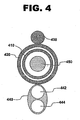
- the fluid delivery catheter 440 may be configured with both a fluid delivery lumen 442 and a separate flushing lumen 444.
- This design permits flushing of the helical cavity following delivery of the photoinitiator without having to flush additional photoinitiator that remains in the fluid delivery lumen into the vessel, thereby minimizing the amount of photoinitiator that enters the vessel.
- the two lumens may be fully separate, or the lumens may bifurcate proximal to a distal common tip.
- the prepolymer may be delivered through the flushing lumen rather than through the fluid delivery lumen.
- the positioning of guidewire catheter 410, pullback catheter 420, fiber optic wire 438, and guidewire 450 is similar to that of system 100.
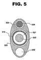
- FIG. 5 shows a cross-sectional view of a proximal segment of another example of a system for treating a vascular condition.
- the system does not include a fluid delivery catheter.
- pullback catheter 520 contains not only a lumen 521 to receive guidewire catheter 510, but also a fluid delivery lumen 542.
- fiber optic wire 538 is contained within pullback catheter 520 as well, running through a wire lumen 525, rather than being affixed to an outer surface of the pullback catheter as in system 100.
- a conduit may be joined to the proximal end of fluid delivery lumen 542 to direct fluids from lumen 542 into the helical channel formed in the fluid channeling structure of this example.
- prepolymer is delivered to the channel until it fills the cavity formed between the channel and the vessel wall.
- the light source operably connected to light emission coil 136 is then activated, causing the coil to deliver light to the vessel wall, thereby curing the prepolymer and forming a polymer (typically a hydrogel) coating on the wall of the vessel.
- Fluid channeling structure 130 may then be returned to its reduced crossing profile by extending guidewire catheter 110 within a stationary pullback catheter 120. Uncured material will be washed away as fluid channeling structure 130 contracts away from the wall of the vessel. Alternatively, uncured material may be removed prior to contracting fluid channeling structure 130 by, for example, pulling a vacuum on fluid delivery catheter 140.
- a system in accordance with the present invention significantly reduces the amount of photoinitiator and prepolymer used in treating a vessel. Because the fluid must fill only the helical cavity between the fluid channeling structure and the wall of the vessel, rather than the entire lumen of the vessel, less than a milliliter of fluid is needed. Further, the flow of a bodily fluid through the vessel is not blocked during treatment, reducing the risk of damage to the vessel and eliminating the need to rush the treatment procedure in order to return flow through the vessel as quickly as possible.
- a coating may be formed on all or part of the inner surface of a treatment device such as a stent or graft positioned within the vessel, or on an inner surface of at least a portion of both the vessel and a treatment device.
- the system may be used to deliver and activate materials other than photopolymerization materials, including, but not limited to, a photoactivated drug or other therapeutic agent.
- FIG. 6 shows a flow diagram of one embodiment of the method in accordance with the present invention.
- a catheter assembly is formed by positioning a proximal portion of an inner catheter within a lumen of an outer catheter (Block 610).
- the inner catheter may be threaded through the lumen of the outer catheter such that a distal portion of the inner catheter extends from the distal end of the outer catheter.
- a proximal portion of the inner catheter may extend from the proximal end of the outer catheter as well.
- a fluid channeling structure is formed by positioning an elastic coil within an elastomeric sleeve and then coiling a fiber optic wire about the elastomeric sleeve (Block 620).
- the fiber optic wire is wrapped tightly about the elastomeric sleeve to form a fiber optic coil that has a diameter smaller than that of the elastic coil.
- Loops of the fiber optic coil are interspaced with (i.e., positioned between) loops of the elastic coil and constrict the elastomeric sleeve between loops of the elastic coil such that a helical channel is formed in the sleeve.
- a distal portion of the catheter assembly is positioned within the fluid channeling structure (Block 630). This may be accomplishes by threading the substantially tubular fluid channeling structure over the distal end of the catheter assembly until a proximal end of the fluid channeling structure is positioned over a distal portion of the outer catheter and a distal end of the fluid channeling structure is positioned over a distal portion of the inner catheter.
- a proximal portion of the fluid channeling structure is attached to a distal portion of the outer catheter (Block 640).
- a proximal portion of the elastic coil may be bonded or otherwise permanently attached to a distal portion of the outer catheter.
- a proximal portion of one or both of the elastomeric sleeve and the fiber optic coil may be similarly affixed to the outer catheter.
- a distal portion of the fluid channeling structure is attached to a distal portion of the inner catheter (Block 650).
- a distal portion of the elastic coil may be bonded or otherwise permanently attached to a distal portion of the inner catheter.
- a distal portion of one or both of the elastomeric sleeve and the fiber optic coil may be similarly affixed to the inner catheter.
- the outer catheter is drawn proximally such that the length of the fluid channeling structure is increased and the diameter of the fluid channeling structure is decreased (Block 660). Because a distal portion of the fluid channeling structure is affixed to the inner catheter, while a proximal portion of the structure is affixed to the outer catheter, pulling the outer catheter in a proximal direction extends the elastic coil longitudinally, thereby reducing the winding diameter of the coil, while at the same time extending and narrowing both the light emission coil and the elastomeric sleeve.
- the proximal end of the catheter assembly may include a locking mechanism to ensure the relative positions of the inner and outer catheters remain fixed throughout delivery of the system to a target treatment area, thereby maintaining the system in an extended and minimized crossing profile.
- FIG. 7 shows a flow diagram of a method for treating a vascular condition.
- a system for treating a vascular condition is delivered to a treatment site within a vessel (Block 710).
- a system such as is described above and illustrated in FIGS. 1 and 2 at 100 may be delivered to a target treatment area within a blood vessel.
- a distal portion of the system is expanded to form a helical cavity between the distal portion and an inner wall of the vessel (Block 720). This may be accomplished as described previously, with fluid channeling structure 130, positioned adjacent to a distal end of system 100, being expanded within a vessel to form a helical cavity 135 between the fluid channeling structure and the inner wall of the vessel.
- a fluid is delivered to the helical cavity (Block 730).
- a prepolymer may be delivered to the cavity after a photoinitiator has been adsorbed on (or otherwise bound to) the inner wall of the vessel. Both the photoinitiator and the prepolymer may be delivered to fluid channeling structure 122 via fluid delivery catheter 140. Excess photoinitiator may be flushed from the cavity using a saline or other flushing solution prior to delivery of the prepolymer.
- the helical cavity is exposed to light along a helical path (Block 740).
- light is conveyed to light emission coil 136 via the proximal portion of the fiber optic wire used to form light emission coil 136, the proximal portion being indicated at 138 in FIGS. 1 and 2 .
- the light forms a helical path defined by the loops of light emission coil 136.
- the prepolymer within the helical cavity is cured or polymerized to form a polymer (typically a hydrogel) coating on the inner wall of the vessel. Fluid channeling structure 130 may then be returned to its reduced crossing profile for withdrawal of the system from the vessel.
Landscapes
- Health & Medical Sciences (AREA)
- Life Sciences & Earth Sciences (AREA)
- General Health & Medical Sciences (AREA)
- Veterinary Medicine (AREA)
- Public Health (AREA)
- Animal Behavior & Ethology (AREA)
- Epidemiology (AREA)
- Chemical & Material Sciences (AREA)
- Engineering & Computer Science (AREA)
- Heart & Thoracic Surgery (AREA)
- Biomedical Technology (AREA)
- Surgery (AREA)
- Anesthesiology (AREA)
- Hematology (AREA)
- Dispersion Chemistry (AREA)
- Vascular Medicine (AREA)
- Biophysics (AREA)
- Pulmonology (AREA)
- Materials Engineering (AREA)
- Dermatology (AREA)
- Medicinal Chemistry (AREA)
- Oral & Maxillofacial Surgery (AREA)
- Transplantation (AREA)
- Surgical Instruments (AREA)
- Materials For Medical Uses (AREA)
- Media Introduction/Drainage Providing Device (AREA)
Applications Claiming Priority (2)
| Application Number | Priority Date | Filing Date | Title |
|---|---|---|---|
| US11/090,783 US7457661B2 (en) | 2005-03-24 | 2005-03-24 | Catheter-based, dual coil photopolymerization system |
| PCT/US2006/008128 WO2006104649A1 (en) | 2005-03-24 | 2006-03-07 | Catheter-based, dual coil photopolymerization system |
Publications (2)
| Publication Number | Publication Date |
|---|---|
| EP1896105A1 EP1896105A1 (en) | 2008-03-12 |
| EP1896105B1 true EP1896105B1 (en) | 2011-11-09 |
Family
ID=36763890
Family Applications (1)
| Application Number | Title | Priority Date | Filing Date |
|---|---|---|---|
| EP06748314A Expired - Lifetime EP1896105B1 (en) | 2005-03-24 | 2006-03-07 | Catheter-based, dual coil photopolymerization system |
Country Status (5)
| Country | Link |
|---|---|
| US (2) | US7457661B2 (enExample) |
| EP (1) | EP1896105B1 (enExample) |
| JP (1) | JP4299364B2 (enExample) |
| AT (1) | ATE532549T1 (enExample) |
| WO (1) | WO2006104649A1 (enExample) |
Families Citing this family (15)
| Publication number | Priority date | Publication date | Assignee | Title |
|---|---|---|---|---|
| US7857748B2 (en) * | 2003-01-15 | 2010-12-28 | Syne Cor, Llc | Photocurable endoprosthesis methods of manufacture |
| US9241735B2 (en) | 2003-12-05 | 2016-01-26 | Onset Medical Corporation | Expandable percutaneous sheath |
| US7780692B2 (en) | 2003-12-05 | 2010-08-24 | Onset Medical Corporation | Expandable percutaneous sheath |
| EP1819391B1 (en) * | 2004-09-09 | 2020-02-19 | Onset Medical Corporation | Expandable transluminal sheath |
| US7892203B2 (en) | 2004-09-09 | 2011-02-22 | Onset Medical Corporation | Expandable transluminal sheath |
| US7891085B1 (en) | 2005-01-11 | 2011-02-22 | Boston Scientific Neuromodulation Corporation | Electrode array assembly and method of making same |
| US7515957B2 (en) * | 2005-06-23 | 2009-04-07 | Medtronic Vascular, Inc. | Catheter-based, dual balloon photopolymerization system |
| US8083726B1 (en) * | 2005-09-30 | 2011-12-27 | Advanced Cardiovascular Systems, Inc. | Encapsulating cells and lumen |
| US9468746B2 (en) | 2006-08-22 | 2016-10-18 | Medtronic Vascular, Inc. | Systems and methods for local bioactive material delivery |
| CN101743032B (zh) * | 2007-03-27 | 2012-09-19 | 因特拉泰克医药有限公司 | 螺旋囊体导管 |
| US8187222B2 (en) * | 2008-09-12 | 2012-05-29 | Boston Scientific Scimed, Inc. | Devices and systems for delivery of therapeutic agents to body lumens |
| US7951110B2 (en) | 2008-11-10 | 2011-05-31 | Onset Medical Corporation | Expandable spinal sheath and method of use |
| EP2574269B1 (en) | 2010-11-25 | 2016-08-31 | Olympus Corporation | Insertion portion rigidity changeable catheter with balloon |
| DE102017210895A1 (de) * | 2017-06-28 | 2019-01-03 | Bayerische Motoren Werke Aktiengesellschaft | Verfahren, Computer-lesbares Medium, System, und Fahrzeug umfassend das System zum Validieren einer Zeitfunktion eines Masters und der Clients in einem Netzwerk eines Fahrzeugs |
| US12414819B2 (en) | 2020-11-03 | 2025-09-16 | The University Of British Columbia | Hydrogel co-injection and real-time opto-electromagnetic modification device for tunable in-vivo delivery |
Family Cites Families (30)
| Publication number | Priority date | Publication date | Assignee | Title |
|---|---|---|---|---|
| US99332A (en) * | 1870-02-01 | Improved composition for paint | ||
| US32916A (en) * | 1861-07-23 | Combined knife | ||
| US2876839A (en) * | 1956-02-08 | 1959-03-10 | Pan American Petroleum Corp | Fracturing formations with a volatile fluid |
| US3560053A (en) * | 1968-11-19 | 1971-02-02 | Exxon Production Research Co | High pressure pumping system |
| US3722595A (en) * | 1971-01-25 | 1973-03-27 | Exxon Production Research Co | Hydraulic fracturing method |
| US3842910A (en) * | 1973-10-04 | 1974-10-22 | Dow Chemical Co | Well fracturing method using liquefied gas as fracturing fluid |
| US4534427A (en) * | 1983-07-25 | 1985-08-13 | Wang Fun Den | Abrasive containing fluid jet drilling apparatus and process |
| DE3425656C2 (de) * | 1984-07-12 | 1994-12-08 | Sero Pumpenfabrik Gmbh | Kreiselpumpe |
| US4878492A (en) * | 1987-10-08 | 1989-11-07 | C. R. Bard, Inc. | Laser balloon catheter |
| WO1990001969A1 (en) | 1988-08-24 | 1990-03-08 | Slepian Marvin J | Biodegradable polymeric endoluminal sealing |
| US5133624A (en) * | 1990-10-25 | 1992-07-28 | Cahill Calvin D | Method and apparatus for hydraulic embedment of waste in subterranean formations |
| DE4216237A1 (de) * | 1992-05-16 | 1993-11-18 | Leybold Ag | Gasreibungsvakuumpumpe |
| US6004547A (en) * | 1997-09-29 | 1999-12-21 | Focal, Inc. | Apparatus and method for local application of polymeric material to tissue |
| US5522459A (en) * | 1993-06-03 | 1996-06-04 | Halliburton Company | Continuous multi-component slurrying process at oil or gas well |
| US6245040B1 (en) * | 1994-01-14 | 2001-06-12 | Cordis Corporation | Perfusion balloon brace and method of use |
| US5632767A (en) * | 1994-09-09 | 1997-05-27 | Rare Earth Medical, Inc. | Loop diffusers for diffusion of optical radiation |
| NL9500493A (nl) * | 1995-03-13 | 1996-10-01 | Cordis Europ | Catheter met lichtgeleider. |
| US5779673A (en) * | 1995-06-26 | 1998-07-14 | Focal, Inc. | Devices and methods for application of intraluminal photopolymerized gels |
| US5720598A (en) * | 1995-10-04 | 1998-02-24 | Dowell, A Division Of Schlumberger Technology Corp. | Method and a system for early detection of defects in multiplex positive displacement pumps |
| FR2748533B1 (fr) * | 1996-05-07 | 1999-07-23 | Inst Francais Du Petrole | Systeme de pompage polyphasique et centrifuge |
| US5799734A (en) * | 1996-07-18 | 1998-09-01 | Halliburton Energy Services, Inc. | Method of forming and using particulate slurries for well completion |
| US5964751A (en) * | 1996-08-26 | 1999-10-12 | Illumenex Corporation | Light delivery system with blood flushing capability |
| US6435277B1 (en) * | 1996-10-09 | 2002-08-20 | Schlumberger Technology Corporation | Compositions containing aqueous viscosifying surfactants and methods for applying such compositions in subterranean formations |
| US5951539A (en) * | 1997-06-10 | 1999-09-14 | Target Therpeutics, Inc. | Optimized high performance multiple coil spiral-wound vascular catheter |
| US6263236B1 (en) * | 1999-11-29 | 2001-07-17 | Illumenex Corporation | Non-occlusive expandable catheter |
| US6701955B2 (en) * | 2000-12-21 | 2004-03-09 | Schlumberger Technology Corporation | Valve apparatus |
| US20050056428A1 (en) * | 2001-09-11 | 2005-03-17 | Commonwealth Scientific And Industrial Research Organization | Hydraulic fracturing of ground formations |
| US20040125688A1 (en) * | 2002-12-30 | 2004-07-01 | Kelley Milton I. | Closed automatic fluid mixing system |
| US20060065400A1 (en) * | 2004-09-30 | 2006-03-30 | Smith David R | Method and apparatus for stimulating a subterranean formation using liquefied natural gas |
| US7326034B2 (en) * | 2005-09-14 | 2008-02-05 | Schlumberger Technology Corporation | Pump apparatus and methods of making and using same |
-
2005
- 2005-03-24 US US11/090,783 patent/US7457661B2/en not_active Expired - Fee Related
-
2006
- 2006-03-07 WO PCT/US2006/008128 patent/WO2006104649A1/en not_active Ceased
- 2006-03-07 JP JP2008503010A patent/JP4299364B2/ja not_active Expired - Fee Related
- 2006-03-07 EP EP06748314A patent/EP1896105B1/en not_active Expired - Lifetime
- 2006-03-07 AT AT06748314T patent/ATE532549T1/de active
-
2008
- 2008-09-23 US US12/235,699 patent/US7653432B2/en not_active Expired - Fee Related
Also Published As
| Publication number | Publication date |
|---|---|
| JP2008534053A (ja) | 2008-08-28 |
| EP1896105A1 (en) | 2008-03-12 |
| JP4299364B2 (ja) | 2009-07-22 |
| ATE532549T1 (de) | 2011-11-15 |
| US20060217653A1 (en) | 2006-09-28 |
| US7457661B2 (en) | 2008-11-25 |
| US20090018487A1 (en) | 2009-01-15 |
| US7653432B2 (en) | 2010-01-26 |
| WO2006104649A1 (en) | 2006-10-05 |
Similar Documents
| Publication | Publication Date | Title |
|---|---|---|
| US7653432B2 (en) | Catheter-based, dual coil photopolymerization system | |
| US7912539B2 (en) | Catheter-based, dual balloon photopolymerization system | |
| US7955365B2 (en) | Closed loop catheter photopolymerization system and method of treating a vascular condition | |
| US6171296B1 (en) | Flow directed catheter | |
| EP1023100B1 (en) | Method of manufacture of a balloon catheter | |
| JP6212031B2 (ja) | 薬物送達のための可変長カテーテル | |
| JP4713478B2 (ja) | 医療器具の送出システム | |
| EP1061986B1 (en) | Angioplasty and stent delivery catheter | |
| US7981148B2 (en) | Stent delivery catheter | |
| US9011374B2 (en) | Balloon catheter with three lumens | |
| US20080091259A1 (en) | Selectively Light Curable Support Members for Medical Devices | |
| CN109862835A (zh) | 用于从血管中移除闭塞凝块的凝块收回系统 | |
| WO1997029716A1 (en) | Endovascular apparatus | |
| CA2774733A1 (en) | Noncircular inner lumen guiding catheter with assisted variable support | |
| CN101588835A (zh) | 长嘴可操纵导管 | |
| CN113384384A (zh) | 支架装载和递送系统 | |
| CN113453742B (zh) | 球囊阻断导管 | |
| US20070225680A1 (en) | Guiding catheter with chemically softened distal portion and method of making same | |
| CN114652946A (zh) | 一种可调弯高扭矩球囊微导管 | |
| CN117679211A (zh) | 一种人工瓣膜及瓣膜输送装置 | |
| HK40057050A (en) | Scaffold loading and delivery systems | |
| CN121648440A (zh) | 一种对损伤血管内药物贴壁递送及灌注装置 |
Legal Events
| Date | Code | Title | Description |
|---|---|---|---|
| PUAI | Public reference made under article 153(3) epc to a published international application that has entered the european phase |
Free format text: ORIGINAL CODE: 0009012 |
|
| 17P | Request for examination filed |
Effective date: 20071024 |
|
| AK | Designated contracting states |
Kind code of ref document: A1 Designated state(s): AT BE BG CH CY CZ DE DK EE ES FI FR GB GR HU IE IS IT LI LT LU LV MC NL PL PT RO SE SI SK TR |
|
| DAX | Request for extension of the european patent (deleted) | ||
| GRAP | Despatch of communication of intention to grant a patent |
Free format text: ORIGINAL CODE: EPIDOSNIGR1 |
|
| GRAS | Grant fee paid |
Free format text: ORIGINAL CODE: EPIDOSNIGR3 |
|
| GRAA | (expected) grant |
Free format text: ORIGINAL CODE: 0009210 |
|
| AK | Designated contracting states |
Kind code of ref document: B1 Designated state(s): AT BE BG CH CY CZ DE DK EE ES FI FR GB GR HU IE IS IT LI LT LU LV MC NL PL PT RO SE SI SK TR |
|
| REG | Reference to a national code |
Ref country code: GB Ref legal event code: FG4D |
|
| REG | Reference to a national code |
Ref country code: CH Ref legal event code: EP |
|
| REG | Reference to a national code |
Ref country code: IE Ref legal event code: FG4D |
|
| REG | Reference to a national code |
Ref country code: DE Ref legal event code: R096 Ref document number: 602006025723 Country of ref document: DE Effective date: 20120209 |
|
| REG | Reference to a national code |
Ref country code: NL Ref legal event code: VDEP Effective date: 20111109 |
|
| LTIE | Lt: invalidation of european patent or patent extension |
Effective date: 20111109 |
|
| PG25 | Lapsed in a contracting state [announced via postgrant information from national office to epo] |
Ref country code: LT Free format text: LAPSE BECAUSE OF FAILURE TO SUBMIT A TRANSLATION OF THE DESCRIPTION OR TO PAY THE FEE WITHIN THE PRESCRIBED TIME-LIMIT Effective date: 20111109 Ref country code: IS Free format text: LAPSE BECAUSE OF FAILURE TO SUBMIT A TRANSLATION OF THE DESCRIPTION OR TO PAY THE FEE WITHIN THE PRESCRIBED TIME-LIMIT Effective date: 20120309 |
|
| PGFP | Annual fee paid to national office [announced via postgrant information from national office to epo] |
Ref country code: FR Payment date: 20120406 Year of fee payment: 7 Ref country code: IE Payment date: 20120326 Year of fee payment: 7 |
|
| PG25 | Lapsed in a contracting state [announced via postgrant information from national office to epo] |
Ref country code: GR Free format text: LAPSE BECAUSE OF FAILURE TO SUBMIT A TRANSLATION OF THE DESCRIPTION OR TO PAY THE FEE WITHIN THE PRESCRIBED TIME-LIMIT Effective date: 20120210 Ref country code: SE Free format text: LAPSE BECAUSE OF FAILURE TO SUBMIT A TRANSLATION OF THE DESCRIPTION OR TO PAY THE FEE WITHIN THE PRESCRIBED TIME-LIMIT Effective date: 20111109 Ref country code: PL Free format text: LAPSE BECAUSE OF FAILURE TO SUBMIT A TRANSLATION OF THE DESCRIPTION OR TO PAY THE FEE WITHIN THE PRESCRIBED TIME-LIMIT Effective date: 20111109 Ref country code: LV Free format text: LAPSE BECAUSE OF FAILURE TO SUBMIT A TRANSLATION OF THE DESCRIPTION OR TO PAY THE FEE WITHIN THE PRESCRIBED TIME-LIMIT Effective date: 20111109 Ref country code: BE Free format text: LAPSE BECAUSE OF FAILURE TO SUBMIT A TRANSLATION OF THE DESCRIPTION OR TO PAY THE FEE WITHIN THE PRESCRIBED TIME-LIMIT Effective date: 20111109 Ref country code: NL Free format text: LAPSE BECAUSE OF FAILURE TO SUBMIT A TRANSLATION OF THE DESCRIPTION OR TO PAY THE FEE WITHIN THE PRESCRIBED TIME-LIMIT Effective date: 20111109 Ref country code: PT Free format text: LAPSE BECAUSE OF FAILURE TO SUBMIT A TRANSLATION OF THE DESCRIPTION OR TO PAY THE FEE WITHIN THE PRESCRIBED TIME-LIMIT Effective date: 20120309 Ref country code: SI Free format text: LAPSE BECAUSE OF FAILURE TO SUBMIT A TRANSLATION OF THE DESCRIPTION OR TO PAY THE FEE WITHIN THE PRESCRIBED TIME-LIMIT Effective date: 20111109 |
|
| PG25 | Lapsed in a contracting state [announced via postgrant information from national office to epo] |
Ref country code: CY Free format text: LAPSE BECAUSE OF FAILURE TO SUBMIT A TRANSLATION OF THE DESCRIPTION OR TO PAY THE FEE WITHIN THE PRESCRIBED TIME-LIMIT Effective date: 20111109 |
|
| PG25 | Lapsed in a contracting state [announced via postgrant information from national office to epo] |
Ref country code: DK Free format text: LAPSE BECAUSE OF FAILURE TO SUBMIT A TRANSLATION OF THE DESCRIPTION OR TO PAY THE FEE WITHIN THE PRESCRIBED TIME-LIMIT Effective date: 20111109 Ref country code: BG Free format text: LAPSE BECAUSE OF FAILURE TO SUBMIT A TRANSLATION OF THE DESCRIPTION OR TO PAY THE FEE WITHIN THE PRESCRIBED TIME-LIMIT Effective date: 20120209 Ref country code: CZ Free format text: LAPSE BECAUSE OF FAILURE TO SUBMIT A TRANSLATION OF THE DESCRIPTION OR TO PAY THE FEE WITHIN THE PRESCRIBED TIME-LIMIT Effective date: 20111109 Ref country code: SK Free format text: LAPSE BECAUSE OF FAILURE TO SUBMIT A TRANSLATION OF THE DESCRIPTION OR TO PAY THE FEE WITHIN THE PRESCRIBED TIME-LIMIT Effective date: 20111109 Ref country code: EE Free format text: LAPSE BECAUSE OF FAILURE TO SUBMIT A TRANSLATION OF THE DESCRIPTION OR TO PAY THE FEE WITHIN THE PRESCRIBED TIME-LIMIT Effective date: 20111109 |
|
| PGFP | Annual fee paid to national office [announced via postgrant information from national office to epo] |
Ref country code: DE Payment date: 20120328 Year of fee payment: 7 |
|
| PG25 | Lapsed in a contracting state [announced via postgrant information from national office to epo] |
Ref country code: RO Free format text: LAPSE BECAUSE OF FAILURE TO SUBMIT A TRANSLATION OF THE DESCRIPTION OR TO PAY THE FEE WITHIN THE PRESCRIBED TIME-LIMIT Effective date: 20111109 Ref country code: IT Free format text: LAPSE BECAUSE OF FAILURE TO SUBMIT A TRANSLATION OF THE DESCRIPTION OR TO PAY THE FEE WITHIN THE PRESCRIBED TIME-LIMIT Effective date: 20111109 |
|
| PLBE | No opposition filed within time limit |
Free format text: ORIGINAL CODE: 0009261 |
|
| STAA | Information on the status of an ep patent application or granted ep patent |
Free format text: STATUS: NO OPPOSITION FILED WITHIN TIME LIMIT |
|
| REG | Reference to a national code |
Ref country code: AT Ref legal event code: MK05 Ref document number: 532549 Country of ref document: AT Kind code of ref document: T Effective date: 20111109 |
|
| 26N | No opposition filed |
Effective date: 20120810 |
|
| PG25 | Lapsed in a contracting state [announced via postgrant information from national office to epo] |
Ref country code: MC Free format text: LAPSE BECAUSE OF NON-PAYMENT OF DUE FEES Effective date: 20120331 |
|
| REG | Reference to a national code |
Ref country code: CH Ref legal event code: PL |
|
| GBPC | Gb: european patent ceased through non-payment of renewal fee |
Effective date: 20120307 |
|
| REG | Reference to a national code |
Ref country code: DE Ref legal event code: R097 Ref document number: 602006025723 Country of ref document: DE Effective date: 20120810 |
|
| PG25 | Lapsed in a contracting state [announced via postgrant information from national office to epo] |
Ref country code: LI Free format text: LAPSE BECAUSE OF NON-PAYMENT OF DUE FEES Effective date: 20120331 Ref country code: AT Free format text: LAPSE BECAUSE OF FAILURE TO SUBMIT A TRANSLATION OF THE DESCRIPTION OR TO PAY THE FEE WITHIN THE PRESCRIBED TIME-LIMIT Effective date: 20111109 Ref country code: CH Free format text: LAPSE BECAUSE OF NON-PAYMENT OF DUE FEES Effective date: 20120331 Ref country code: GB Free format text: LAPSE BECAUSE OF NON-PAYMENT OF DUE FEES Effective date: 20120307 |
|
| PG25 | Lapsed in a contracting state [announced via postgrant information from national office to epo] |
Ref country code: ES Free format text: LAPSE BECAUSE OF FAILURE TO SUBMIT A TRANSLATION OF THE DESCRIPTION OR TO PAY THE FEE WITHIN THE PRESCRIBED TIME-LIMIT Effective date: 20120220 |
|
| PG25 | Lapsed in a contracting state [announced via postgrant information from national office to epo] |
Ref country code: FI Free format text: LAPSE BECAUSE OF FAILURE TO SUBMIT A TRANSLATION OF THE DESCRIPTION OR TO PAY THE FEE WITHIN THE PRESCRIBED TIME-LIMIT Effective date: 20111109 |
|
| REG | Reference to a national code |
Ref country code: FR Ref legal event code: ST Effective date: 20131129 |
|
| REG | Reference to a national code |
Ref country code: IE Ref legal event code: MM4A |
|
| REG | Reference to a national code |
Ref country code: DE Ref legal event code: R119 Ref document number: 602006025723 Country of ref document: DE Effective date: 20131001 |
|
| PG25 | Lapsed in a contracting state [announced via postgrant information from national office to epo] |
Ref country code: FR Free format text: LAPSE BECAUSE OF NON-PAYMENT OF DUE FEES Effective date: 20130402 Ref country code: DE Free format text: LAPSE BECAUSE OF NON-PAYMENT OF DUE FEES Effective date: 20131001 Ref country code: IE Free format text: LAPSE BECAUSE OF NON-PAYMENT OF DUE FEES Effective date: 20130307 |
|
| PG25 | Lapsed in a contracting state [announced via postgrant information from national office to epo] |
Ref country code: TR Free format text: LAPSE BECAUSE OF FAILURE TO SUBMIT A TRANSLATION OF THE DESCRIPTION OR TO PAY THE FEE WITHIN THE PRESCRIBED TIME-LIMIT Effective date: 20111109 |
|
| PG25 | Lapsed in a contracting state [announced via postgrant information from national office to epo] |
Ref country code: LU Free format text: LAPSE BECAUSE OF NON-PAYMENT OF DUE FEES Effective date: 20120307 |
|
| PG25 | Lapsed in a contracting state [announced via postgrant information from national office to epo] |
Ref country code: HU Free format text: LAPSE BECAUSE OF FAILURE TO SUBMIT A TRANSLATION OF THE DESCRIPTION OR TO PAY THE FEE WITHIN THE PRESCRIBED TIME-LIMIT Effective date: 20060307 |