EP1895535A2 - Plattenwiedergabegerät - Google Patents
Plattenwiedergabegerät Download PDFInfo
- Publication number
- EP1895535A2 EP1895535A2 EP07016838A EP07016838A EP1895535A2 EP 1895535 A2 EP1895535 A2 EP 1895535A2 EP 07016838 A EP07016838 A EP 07016838A EP 07016838 A EP07016838 A EP 07016838A EP 1895535 A2 EP1895535 A2 EP 1895535A2
- Authority
- EP
- European Patent Office
- Prior art keywords
- repeat
- reproduction
- point
- control unit
- image data
- Prior art date
- Legal status (The legal status is an assumption and is not a legal conclusion. Google has not performed a legal analysis and makes no representation as to the accuracy of the status listed.)
- Withdrawn
Links
- 238000000034 method Methods 0.000 description 9
- 238000010586 diagram Methods 0.000 description 6
- 230000006870 function Effects 0.000 description 5
- 230000003287 optical effect Effects 0.000 description 5
- 230000002596 correlated effect Effects 0.000 description 3
- 230000006835 compression Effects 0.000 description 2
- 238000007906 compression Methods 0.000 description 2
- 230000000875 corresponding effect Effects 0.000 description 1
- 230000015654 memory Effects 0.000 description 1
- 238000005204 segregation Methods 0.000 description 1
- 230000005236 sound signal Effects 0.000 description 1
- 230000003936 working memory Effects 0.000 description 1
Images

Classifications
-
- G—PHYSICS
- G11—INFORMATION STORAGE
- G11B—INFORMATION STORAGE BASED ON RELATIVE MOVEMENT BETWEEN RECORD CARRIER AND TRANSDUCER
- G11B27/00—Editing; Indexing; Addressing; Timing or synchronising; Monitoring; Measuring tape travel
- G11B27/005—Reproducing at a different information rate from the information rate of recording
- G11B27/007—Reproducing at a different information rate from the information rate of recording reproducing continuously a part of the information, i.e. repeating
-
- G—PHYSICS
- G11—INFORMATION STORAGE
- G11B—INFORMATION STORAGE BASED ON RELATIVE MOVEMENT BETWEEN RECORD CARRIER AND TRANSDUCER
- G11B2220/00—Record carriers by type
- G11B2220/20—Disc-shaped record carriers
- G11B2220/25—Disc-shaped record carriers characterised in that the disc is based on a specific recording technology
- G11B2220/2537—Optical discs
- G11B2220/2562—DVDs [digital versatile discs]; Digital video discs; MMCDs; HDCDs
Definitions
- the present invention relates to a disk reproducing apparatus capable of reproducing image data recorded on a disk-shaped recording medium, such as a digital versatile disk (DVD), and more particularly to a disk reproducing apparatus including an A-B repeat reproduction function.
- a disk reproducing apparatus capable of reproducing image data recorded on a disk-shaped recording medium, such as a digital versatile disk (DVD), and more particularly to a disk reproducing apparatus including an A-B repeat reproduction function.
- MPEG Moving Picture Coding Expert Group
- VOBU video object unit
- GOP group of pictures
- the image data in a VOBU is generally composed of three kinds of pictures of I/P/B pictures, and each frame in the VOBU is distributed to any of the I picture, the P picture, and the B picture to be coded.
- the I picture indicates a screen capable of being compressed using only the information in its own screen without using the correlated information of the other screens before and after the screen in time, and the compression similar to the compression of the Joint Photographic Experts Group (JPEG) is performed to the I picture as a still image (intra-frame encoding).
- the P picture indicates a screen expressed by the correlated information from a past screen in time, and is coded by referring to a past I picture or a past P picture (forward prediction).
- the B picture indicates a screen expressed by the correlated information from before and after screens in time, and is coded by referring to an I picture or a P picture (both-direction prediction).
- the I picture is first reconstructed, and then the P picture and the B picture are reconstructed on the basis of the I picture.
- a method of only reproducing (displaying) the I pictures is general (the P pictures can be also used for the fast-forward reproduction). That is, in the fast-forward reproduction and the fast-backward reproduction, I pictures before (past) and after (future) predetermined times are sequentially displayed. For example, an I picture before or after a predetermined number of VOBUs by the VOBU (e.g., the first I picture at the VOBU) is displayed.
- some disk reproducing apparatus include the A-B repeat reproduction function of setting a repeat starting point (point A) and a repeat ending point (point B) with an input unit of a remote control apparatus or the like during the reproduction of image data, and of repeating reproduction in the A-B section.
- Japanese Patent Application Laid-Open Publications No. 2004-241051 , No. 2003-235014 , No. 2005-071551 , and No. 2001-126380 disclose techniques pertaining to the A-B repeat reproduction.
- the fast-forward reproduction and the fast-backward reproduction can be executed even during the A-B repeat reproduction, and the I pictures are displayed at predetermined time intervals (e.g. at each time of skipping two VOBUs) also in this case.
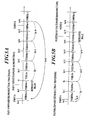
- FIGS. 5A and 5B are explanatory diagrams showing fast-forward reproduction processing and fast-backward reproduction processing, respectively, at the A-B repeat reproduction, and the FIGS. 5A and 5B show the case where the point A (repeat starting point) is set in VOBU #n-2 reproduction and the point B (repeat ending point) is set in VOBU #n+5 reproduction.
- the FIGS. 5A and 5B show the case where the first I picture in each VOBU is reproduced in both of the fast-forward reproduction and the fast-backward reproduction for simplifying the description, there are the cases where the I pictures in the inner parts of the VOBUs are reproduced.
- the fast-forward reproduction e.g. skipping two VOBUs
- the I pictures are reproduced in the order of the first I picture I n in VOBU #n, the first I picture I n+2 in VOBU #n+2, ....
- the first I picture I n+6 in VOBU #n+6 it is judged that the fast-forward reproduction has been performed to the point B, and the reproduction returns to the point A to repeat the A-B repeat reproduction.
- the judgment of the arrival of the fast-forward reproduction at the point B is performed on the basis of the time information of the point B and the reproduced time information of the I pictures. Consequently, the arrival of the fast-forward reproduction at the point B cannot be judged until the I picture I n+6 , which has passed the point B, is reproduced. Consequently, during the period of from the time when the judgment of the arrival of the fast-forward reproduction at the point B has been made to the time when the fast-forward reproduction returns to the point A, the I picture I n+6 , which is an image out of the A-B section, is being displayed.
- the fast-backward reproduction e.g. skipping two VOBUs
- the I pictures are reproduced in the order of the first I picture I n+4 in the VOBU #n+4, the first I picture I n+2 in VOBU #n+2, ....
- the first I picture I n-2 in VOBU #n-2 is reproduced, it is judged that the fast-backward reproduction has been performed to the point A, and the reproduction returns to the point A to repeat the A-B repeat reproduction. Consequently, also in the first-backward reproduction, during the period to the time when the fast-backward reproduction returns to the point A, the I picture I n-2 , which is an image out of the A-B section, is similarly being displayed.
- the images out of the A-B section are displayed during the period of from the time when the fast-forward reproduction or the fast-backward reproduction has passed an end point of the A-B section (point A or point B) to the time when the processing returns to the point A. Consequently, there is the possibility that the display of the images out of the set section may make a user uncomfortable.
- a main object of the present invention to provide a disk reproducing apparatus capable of preventing the display of images out of a set repeat section in the case where special reproduction processing (fast-forward reproduction and fast-backward reproduction) is executed during A-B repeat reproduction.
- a disk reproducing apparatus including: a reproduction control unit to control reproduction processing of image data recorded on a disk-shaped recording medium; a repeat section setting unit to set a repeat starting point (point A) and a repeat ending point (point B) of a repeat section (A-B section) based upon an input of an instruction signal from an input unit during the reproduction processing of the image data; a repeat reproduction control unit to perform repeat reproduction by repeatedly reproducing the image data in the repeat section (A-B section); a special reproduction control unit to control fast-forward reproduction and fast-backward reproduction during the repeat reproduction by the repeat reproduction control unit; and an on-screen display unit capable of displaying a sub-image, by superimposing the sub-image onto a main image, wherein the repeat section setting unit sets time information at the repeat starting point (point A) and the repeat ending point (point B), and stores image data of the repeat starting point (point A) and the repeat ending point (point B), the special reproduction control unit performs special reproduction by reproducing I pictures included
- a disk reproducing apparatus including: a reproduction control unit to control reproduction processing of image data recorded on a disk-shaped recording medium; a repeat section setting unit to set a repeat starting point (point A) and a repeat ending point (point B) of a repeat section (A-B section) based upon an input of an instruction signal from an input unit during the reproduction processing of the image data; a repeat reproduction control unit to perform repeat reproduction by repeatedly reproducing the image data in the repeat section (A-B section) set by the repeat section setting unit; a special reproduction control unit to control fast-forward reproduction and fast-backward reproduction during the repeat reproduction by the repeat reproduction control unit; and an on-screen display unit capable of displaying a sub-image, by superposing the sub-image onto a main image, wherein the repeat section setting unit sets time information at the repeat starting point (point A) and the repeat ending point (point B), and stores image data at the repeat starting point (point A) and/or the repeat ending point (point B), the special reproduction control
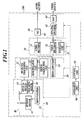
- FIG. 1 is a block diagram of a DVD player 100 as an embodiment of a disk reproducing apparatus according to the present invention.
- the DVD player 100 of the present embodiment includes a disk drive 10 for reading data from a disk-shaped recording medium, such as a DVD, a digital signal processing unit 20 converting a radio frequency (RF) signal obtained by the disk drive 10 into predetermined digital data, a decode unit 30 reconstructing processed compressed data by expanding the compressed data, an output unit 40, a control unit 50, and an operation unit 60.
- a disk drive 10 for reading data from a disk-shaped recording medium, such as a DVD
- RF radio frequency
- the disk drive 10 includes a spindle motor 11, an optical pickup 13, a tracking motor 14, and a servo system 12.
- the spindle motor 11 rotates a disk-shaped recording medium M, such as a DVD.
- the tracking motor 14 operates the optical pickup 13, and the optical pickup 13 reads the data recorded on the disk-shaped recording medium M. To put it concretely, the optical pickup 13 radiates a predetermined laser light to the disk-shaped recording medium M, and receives a reflected light.
- the digital signal processing unit 20 includes an RF signal processing unit 21, a demodulator unit 22, an error correcting unit 23, and a demultiplexer 24.
- the RF signal processing unit 21 converts a waveform signal (RF signal) of a reflected light received by the optical pickup 13 into digital data.
- the demodulator unit 22 demodulates the digital data, which is record-coded by a predetermined modulation method (e.g., 8/16 modulation), into the original data thereof.
- the error correcting unit 23 performs the error correction of demodulated data by a predetermined error correction method (e.g., Reed-Solomon Product-like Code (RS-PC) method).
- RS-PC Reed-Solomon Product-like Code
- the decode unit 30 includes an audio decoder 31 and a video decoder 32.
- the audio decoder 31 expands audio data compressed by a predetermined method (e.g., Dolby AC-3 system) to reconstruct the compressed audio data to the original state thereof.
- the video decoder 32 expands image data compressed by a predetermined method (e.g., Moving Picture Expert Group phase 2 (MPEG-2) system) to reconstruct the image data to the original state.
- MPEG-2 Moving Picture Expert Group phase 2
- the image data at the points A and B which data has been reconstructed by the video decoder 32, is stored in a storage unit 33.
- the image data at the point A or B, which data is stored in the storage unit 33 is on-screen-displayed to be superimposed on a main image when special reproduction (fast-forward reproduction or fast-backward reproduction) in the A-B repeat reproduction reaches an end point (point A or point B) (on-screen display unit).
- the output unit 40 includes an NTSC/PAL encoder 42 and D/A converters 41 and 43.
- the D/A converter 41 analog-converts an audio signal reconstructed by the audio decoder 31 (e.g., linear pulse code modulation (PCM)), and outputs the converted analog signal.
- the NTSC/PAL encoder 42 encodes a video signal reconstructed by the video decoder 32 or a video signal composed with on-screen display (OSD) data (image data at the point A or B) into the data of the national television system committee (NTSC) system or the phase alternation by line (PAL) system in order that the video signal can be seen on a television receiver.
- the D/A converter 43 converts the digital data encoded by the NTSC/PAL encoder 42 into an analog signal to output the analog signal.
- the control unit 50 includes a central processing unit (CPU) performing the control of each block and predetermined operations to control the operation of the DVD player 100, a random access memory (RAM) used as the working memory of the CPU, and a read only memory (ROM) storing control programs to be executed by the CPU and the like.
- CPU central processing unit
- RAM random access memory
- ROM read only memory
- the operation unit 60 can input an instruction signal for setting a repeat starting point (point A) and a repeat ending point (point B) of A-B repeat reproduction into the control unit 50, and is composed of, for example, an operation panel of the apparatus main body or a remote control apparatus.
- the DVD player 100 of the present embodiment has the A-B repeat reproduction function of repeatedly reproducing the repeat section (A-B section) when the repeat starting point (point A) and the repeat ending point (point B) are set by the operation unit 60 during the reproduction of image data.
- control unit 50 functions as a reproduction control unit to control the reproduction processing of the image data recorded on a DVD, a repeat section setting unit to set a repeat starting point (point A) and a repeat ending point (point B), a repeat reproduction control unit to perform repeat reproduction by repeatedly reproducing the image data in a set repeat section, and as a special reproduction control unit to control fast-forward reproduction or fast-backward reproduction in A-B repeat reproduction based upon an instruction signal input from the operation unit 60 during reproduction processing of image data.
- FIGS. 2A and 2B are explanatory diagrams showing fast-forward reproduction processing and fast-backward reproduction processing, respectively, at the time of A-B repeat reproduction.
- FIGS. 2A and 2B show the case where the first I picture of each VOBU is reproduced in the fast-forward reproduction and the fast-backward reproduction for simplifying the description, there are the cases where the I pictures in the internal part of each VOBU are reproduced.
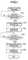
- FIG. 3 is a flow chart showing the A-B repeat setting processing executed by the control unit 50 as the repeat section setting unit.
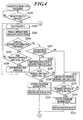
- FIG. 4 is a flow chart showing the A-B repeat reproduction processing executed by the control unit 50 as the repeat reproduction control unit and the special reproduction control unit.
- Step S101 in FIG. 3 it is judged whether an operation for setting a repeat starting point (point A) is performed or not. If it is judged that the setting processing of the point A is performed, then the time information T a of the point A is set (Step S102), and the image data I a of the point A is stored in the storage unit 33 (Step S103).
- FIGS. 2A and 2B show the case where the point A is set in the reproduction of VOBU #n-2.
- Step S104 it is judged whether an operation of setting a repeat ending point (point B) is performed or not. If it is judged that the setting operation of the point B is performed, the time information T b of the point B is set (Step S105), and the image data I b at the point B is stored into the storage unit 33 (Step S106).
- FIGS. 2A and 2B show the case where the point B is set in the reproduction of VOBU #n+5.
- the repeat section is set.
- the image data at the points A and B may be any of an I picture, a P picture, and a B picture.
- Step S201 of FIG. 4 it is judged whether the points A and B are set by the A-B repeat setting processing or not. If it is judged that both of the points A and B are set, the processing moves to the point A on the basis of the time information T a of the point A (Step S202), and normal reproduction processing (A-B repeat reproduction) is executed (Step S203) .
- the normal A-B repeat reproduction processing the image data of the I/P/B pictures included in each VOBU is sequentially reproduced.
- an I picture is first reconstructed; a P picture is then reconstructed on the basis of the I picture; a B picture is finally reconstructed on the basis of the I picture and the P picture; thus each of the I/P/B pictures are reproduced.
- Step S207 If it is judged that the instruction signal of the special reproduction is not input, then the processing shifts to Step S205.
- Step S205 it is judged whether the normal A-B repeat reproduction reaches the point B or not. For example, it is judged whether the reproduction reaches the point B or not on the basis of the time information T b of the point B and the time information T m of the image data to be reproduced. If it is judged that the reproduction reaches the point B, then the reproduction is stopped (Step S206), and the processing shifts to Step S202 to repeat the A-B repeat reproduction processing from the point A. Incidentally, during the period of from the stop of the reproduction at the Step S206 to the return to the point A, the image based on the image data I b at the point B is displayed.
- Step S207 it is judged whether the instructed special reproduction is the fast-backward reproduction or the fast-forward reproduction. If it is judged that the instructed special reproduction is the fast-backward reproduction, then the processing shifts to Step S208 to perform the fast-backward reproduction processing.
- the fast-backward reproduction processing the I pictures included in the image data are skipped at a predetermined time interval (for example, skipping of two VOBUs) in reading, and the read I pictures are reproduced. For example, as shown in FIG.
- Step S209 it is judged whether the fast-backward reproduction reaches the point A or not. At this time, it is judged whether the fast-backward reproduction has reached the point A or not on the basis of the time information T m of the I pictures to be reproduced and the time information T a of the point A. For example, as shown in FIG. 2B, if the time information T n-2 of the first I picture I n-2 of VOBU #n-2 is compared with the time information T a of the point A, then the time information T a is larger than the time information T n-2 . Consequently, it can be judged that the fast-backward reproduction reaches the point A.
- Step S210 if it is judged that the fast-backward reproduction reaches the point A, then the fast-backward reproduction is stopped (Step S210), and the image based on the image data I a at the point A is on-screen-displayed (Step S211) .
- the processing shifts to the Step S202, and repeats the A-B repeat reproduction processing from the point A.
- the image based on the image data I a at the point A is displayed. That is, because the image data I a is displayed on the screen, although the first I picture I n-2 is being reproduced as the main image, the user cannot observes the first I picture I n-2 .
- Step S207 if it is judged that the instructed special reproduction is the fast-backward reproduction at the Step S207, the processing shifts to Step S212, and the fast-forward reproduction processing is performed.
- the I pictures included in the image data are skipped at a predetermined time interval (for example, skipping of two VOBUs) in reading, and the read I Pictures are reproduced.
- a predetermined time interval for example, skipping of two VOBUs
- the fast-forward reproduction is instructed at the point C where the image data of VOBU #n-1 is reproduced by the A-B repeat reproduction, then the I pictures are reproduced in the order of the first I picture I n of VOBU #n, the first I picture I n+2 of VOBU #n+2, ....
- Step S213 it is judged whether the fast-forward reproduction reaches the point B or not. At this time, it is judged whether the fast-forward reproduction reaches the point B or not on the basis of the time information T m of the I pictures to be reproduced and the time information T b of the point B. For example, as shown in FIG. 2A, if the time information T n+6 of the first I picture I n+6 in the VOBU #n+6 is compared with the time information T b of the point B, then the time information T b is smaller than the time information T n+6 . Consequently, it can be judged that the fast-forward reproduction reaches the point B.
- Step S213 If it is judged at the Step S213 that the fast-forward reproduction reaches the point B, then the fast-forward reproduction is stopped (Step S214), and the image based on the image data I b at the point B is on-screen-displayed (Step S215). After that, the processing shifts to the Step S202, and the A-B repeat reproduction processing is repeated from the point A.
- the image based on the image data I b at the point B is displayed. That is, although the first I picture I n+6 is being reproduced as the main image, the I picture I b is displayed on the screen. Consequently, the user cannot observe the first I picture I n+6 .
- the time information T a and T b of the point A (repeat starting point) and the point B (repeat ending point), respectively, are set on the basis of the instruction signal from the operation unit 60, and the image data I a and I b at the points A and B, respectively, are stored. If the special reproduction (fast-forward reproduction or fast-backward reproduction) in A-B repeat reproduction reaches an end point (point A or point B) of the repeat section, then the image based on the image data I a or I b at the point A or B, respectively, is on-screen-displayed.
- the image of the point A or B can be smoothly on-screen-displayed if the reproduced I picture passes through the end point of the repeat section.
- the aforesaid embodiment displays the image based on the image data at the point B when the fast-forward reproduction reaches the point B
- the image based on the image data of the point A may be displayed even if the fast-forward reproduction reaches the point B. That is, because the A-B repeat reproduction is performed by returning the reproduction to the point A even if the fast-forward reproduction reaches the point B, a user does not have an uncomfortable feeling even if the image at the point A is being displayed as a sub-image before the image at the point A is reproduced as the main image.
- the set repeat section may be canceled, and normal reproduction processing may be performed from the time point.
- the A-B repeat reproduction processing may be performed from the time point, or the set repeat section may be canceled and the normal reproduction processing may be performed from the time point.
- a disk reproducing apparatus including: a reproduction control unit to control reproduction processing of image data recorded on a disk-shaped recording medium; a repeat section setting unit to set a repeat starting point (point A) and a repeat ending point (point B) of a repeat section (A-B section) based upon an input of an instruction signal from an input unit during the reproduction processing of the image data; a repeat reproduction control unit to perform repeat reproduction by repeatedly reproducing the image data in the repeat section (A-B section) set by the repeat section setting unit; a special reproduction control unit to control fast-forward reproduction and fast-backward reproduction during the repeat reproduction by the repeat reproduction control unit; and an on-screen display unit capable of displaying a sub-image, by superposing the sub-image onto a main image, wherein the repeat section setting unit sets time information at the repeat starting point (point A) and the repeat ending point (point B), and stores image data at the repeat starting point (point A) and/or the repeat ending point (point B), the
- the special reproduction control section judges whether the special reproduction reaches the end point (point A or point B) of the repeat section (A-B section) or not based upon time information of reproduced I pictures and the time information of the repeat starting point (point A) or the repeat ending point (point B), and if a reproduced I picture exceeds the repeat section (A-B section), then the special reproduction control unit reproduces the I picture, and makes the on-screen display unit display the image based on the image data at the repeat starting point (point A) or the repeat ending point (point B) by superimposing the image onto the I picture.
- the special reproduction control unit estimates time information of an I picture to be reproduced next based upon time information of an I picture currently reproduced and the predetermined time interval to be skipped in the special reproduction, and thereby judges whether the special reproduction reaches the end point (point A or point B) of the repeat section (A-B section) or not.
- the special reproduction control unit makes the on-screen display unit display the image based on the image data at the repeat ending point(point B), and when the fast-backward reproduction reaches the repeat starting point(point A), the special reproduction control unit makes the on-screen display unit display the image based on the image data at the repeat starting point(point A).
- the disk reproducing apparatus having the A-B repeat reproduction function sets the time information of the point A (repeat starting point) and the point B (repeat ending point) on the basis of the instruction signal from the input unit, and stores the image data at the points A and/or B.
- the special reproduction fast-forward reproduction or fast-backward reproduction
- the disk reproducing apparatus on-screen-displays the image based on the image data at the point A or B. Consequently, images out of the repeat section, which a user has set, do not displayed, and it can be prevented that the display of the images out of the set repeat section makes the user uncomfortable.
Landscapes
- Television Signal Processing For Recording (AREA)
- Indexing, Searching, Synchronizing, And The Amount Of Synchronization Travel Of Record Carriers (AREA)
- Signal Processing For Digital Recording And Reproducing (AREA)
Applications Claiming Priority (1)
| Application Number | Priority Date | Filing Date | Title |
|---|---|---|---|
| JP2006230602A JP4214489B2 (ja) | 2006-08-28 | 2006-08-28 | ディスク再生装置 |
Publications (2)
| Publication Number | Publication Date |
|---|---|
| EP1895535A2 true EP1895535A2 (de) | 2008-03-05 |
| EP1895535A3 EP1895535A3 (de) | 2012-06-13 |
Family
ID=38691839
Family Applications (1)
| Application Number | Title | Priority Date | Filing Date |
|---|---|---|---|
| EP07016838A Withdrawn EP1895535A3 (de) | 2006-08-28 | 2007-08-28 | Plattenwiedergabegerät |
Country Status (3)
| Country | Link |
|---|---|
| US (1) | US7978961B2 (de) |
| EP (1) | EP1895535A3 (de) |
| JP (1) | JP4214489B2 (de) |
Families Citing this family (2)
| Publication number | Priority date | Publication date | Assignee | Title |
|---|---|---|---|---|
| JP5284074B2 (ja) * | 2008-12-18 | 2013-09-11 | キヤノン株式会社 | 画像処理装置及び画像処理方法 |
| JP2012185899A (ja) * | 2011-02-15 | 2012-09-27 | Jvc Kenwood Corp | 再生装置、再生方法、及び、プログラム |
Citations (2)
| Publication number | Priority date | Publication date | Assignee | Title |
|---|---|---|---|---|
| JP2002304790A (ja) | 2001-04-09 | 2002-10-18 | Matsushita Electric Ind Co Ltd | 映像記録装置 |
| JP2006180130A (ja) | 2004-12-21 | 2006-07-06 | Funai Electric Co Ltd | 光ディスク再生装置 |
Family Cites Families (7)
| Publication number | Priority date | Publication date | Assignee | Title |
|---|---|---|---|---|
| JP3157963B2 (ja) * | 1993-08-27 | 2001-04-23 | パイオニア株式会社 | 光ディスク再生装置 |
| JP3487339B2 (ja) | 1999-10-22 | 2004-01-19 | 船井電機株式会社 | ディスク装置 |
| JP2001268576A (ja) * | 2000-03-17 | 2001-09-28 | Toshiba Corp | 符号化画像データ再生装置 |
| JP2003235014A (ja) | 2002-02-12 | 2003-08-22 | Denon Ltd | 光ディスク再生装置 |
| JP2004241051A (ja) | 2003-02-06 | 2004-08-26 | Matsushita Electric Ind Co Ltd | 画像再生方法 |
| JP2005071551A (ja) | 2003-08-28 | 2005-03-17 | Funai Electric Co Ltd | ディスク再生装置及びその制御方法 |
| KR100582956B1 (ko) * | 2003-11-28 | 2006-05-23 | 엘지전자 주식회사 | 멀티 미디어 기기에서의 구간 반복 재생방법 |
-
2006
- 2006-08-28 JP JP2006230602A patent/JP4214489B2/ja not_active Expired - Fee Related
-
2007
- 2007-08-28 EP EP07016838A patent/EP1895535A3/de not_active Withdrawn
- 2007-08-28 US US11/845,957 patent/US7978961B2/en not_active Expired - Fee Related
Patent Citations (2)
| Publication number | Priority date | Publication date | Assignee | Title |
|---|---|---|---|---|
| JP2002304790A (ja) | 2001-04-09 | 2002-10-18 | Matsushita Electric Ind Co Ltd | 映像記録装置 |
| JP2006180130A (ja) | 2004-12-21 | 2006-07-06 | Funai Electric Co Ltd | 光ディスク再生装置 |
Also Published As
| Publication number | Publication date |
|---|---|
| JP2008054194A (ja) | 2008-03-06 |
| EP1895535A3 (de) | 2012-06-13 |
| JP4214489B2 (ja) | 2009-01-28 |
| US20080050090A1 (en) | 2008-02-28 |
| US7978961B2 (en) | 2011-07-12 |
Similar Documents
| Publication | Publication Date | Title |
|---|---|---|
| US7359615B2 (en) | Method and device for ensuring storage time for digital broadcast | |
| EP0876063B1 (de) | Signalwiedergabeanlage und -Verfahren | |
| KR100657241B1 (ko) | 동영상 기록/재생 장치와 방법 및 기록 매체 | |
| EP0987895B1 (de) | Informationsaufzeichnungssystem und Informationsaufzeichnungsverfahren | |
| US6363208B2 (en) | Digital signal reproduction method and apparatus | |
| US7978961B2 (en) | Disk reproducing apparatus | |
| US20060002261A1 (en) | Data reproduction apparatus having resume reproduction function, and program product for implementing resume reproduction function | |
| JP4191385B2 (ja) | Mpeg符号化信号のトリックプレイ再生 | |
| US20070279267A1 (en) | Compressed data transfer apparatus and compressed data transfer method | |
| JP2006121183A (ja) | 映像記録再生装置 | |
| JP2004159082A (ja) | 画像編集プログラム及び画像編集装置 | |
| JP4454535B2 (ja) | チャプター情報表示方法および記録媒体再生装置 | |
| KR100708208B1 (ko) | 동영상 재생 장치와 방법 | |
| JP4199780B2 (ja) | 光ディスク再生装置、および再生方法 | |
| JP2004208315A (ja) | 早送りモードのmpegピクチャを復号し、表示する方法および装置、そのような装置が組み込まれたビデオドライバ回路およびデコーダボックス | |
| KR20040089508A (ko) | 영상 신호 기록 장치 및 방법, 및, 영상 신호 출력 장치및 방법 | |
| JP2002157820A (ja) | 記録媒体再生装置、および情報記録媒体 | |
| JP4487262B2 (ja) | 画像出力装置及び画像出力方法 | |
| JP4568148B2 (ja) | 画像記録装置 | |
| JP3508238B2 (ja) | ディスク装置、光ディスクの録画方法及び再生方法 | |
| JP2006319645A (ja) | 映像再生装置及び方法及びプログラム及び記憶媒体 | |
| JP2009060502A (ja) | 電子機器、出力方法及びプログラム | |
| JP2007129489A (ja) | 映像再生装置および映像再生方法 | |
| JP2004015826A (ja) | ディスク状記録媒体の記録方法及び記録装置 | |
| JP2006270633A (ja) | 画像記録装置 |
Legal Events
| Date | Code | Title | Description |
|---|---|---|---|
| PUAI | Public reference made under article 153(3) epc to a published international application that has entered the european phase |
Free format text: ORIGINAL CODE: 0009012 |
|
| AK | Designated contracting states |
Kind code of ref document: A2 Designated state(s): AT BE BG CH CY CZ DE DK EE ES FI FR GB GR HU IE IS IT LI LT LU LV MC MT NL PL PT RO SE SI SK TR |
|
| AX | Request for extension of the european patent |
Extension state: AL BA HR MK YU |
|
| PUAL | Search report despatched |
Free format text: ORIGINAL CODE: 0009013 |
|
| AK | Designated contracting states |
Kind code of ref document: A3 Designated state(s): AT BE BG CH CY CZ DE DK EE ES FI FR GB GR HU IE IS IT LI LT LU LV MC MT NL PL PT RO SE SI SK TR |
|
| AX | Request for extension of the european patent |
Extension state: AL BA HR MK RS |
|
| RIC1 | Information provided on ipc code assigned before grant |
Ipc: G11B 27/00 20060101AFI20120504BHEP |
|
| 17P | Request for examination filed |
Effective date: 20121109 |
|
| AKX | Designation fees paid |
Designated state(s): DE FR |
|
| 17Q | First examination report despatched |
Effective date: 20130708 |
|
| STAA | Information on the status of an ep patent application or granted ep patent |
Free format text: STATUS: THE APPLICATION IS DEEMED TO BE WITHDRAWN |
|
| 18D | Application deemed to be withdrawn |
Effective date: 20150303 |