EP1895151B1 - Prüfvorrichtung und Verfahren zum Justieren einer Prüfvorrichtung für ein nockengetriebenes Kraftstoff-Einspritzsystem, insbesondere ein Pumpe-Düse- oder Pumpe-Leitung-Düse-Einspritzsystem. - Google Patents
Prüfvorrichtung und Verfahren zum Justieren einer Prüfvorrichtung für ein nockengetriebenes Kraftstoff-Einspritzsystem, insbesondere ein Pumpe-Düse- oder Pumpe-Leitung-Düse-Einspritzsystem. Download PDFInfo
- Publication number
- EP1895151B1 EP1895151B1 EP07112117.2A EP07112117A EP1895151B1 EP 1895151 B1 EP1895151 B1 EP 1895151B1 EP 07112117 A EP07112117 A EP 07112117A EP 1895151 B1 EP1895151 B1 EP 1895151B1
- Authority
- EP
- European Patent Office
- Prior art keywords
- cam
- cam shaft
- injection system
- fuel injection
- stroke
- Prior art date
- Legal status (The legal status is an assumption and is not a legal conclusion. Google has not performed a legal analysis and makes no representation as to the accuracy of the status listed.)
- Active
Links
Images


Classifications
-
- F—MECHANICAL ENGINEERING; LIGHTING; HEATING; WEAPONS; BLASTING
- F02—COMBUSTION ENGINES; HOT-GAS OR COMBUSTION-PRODUCT ENGINE PLANTS
- F02M—SUPPLYING COMBUSTION ENGINES IN GENERAL WITH COMBUSTIBLE MIXTURES OR CONSTITUENTS THEREOF
- F02M65/00—Testing fuel-injection apparatus, e.g. testing injection timing ; Cleaning of fuel-injection apparatus
-
- F—MECHANICAL ENGINEERING; LIGHTING; HEATING; WEAPONS; BLASTING
- F02—COMBUSTION ENGINES; HOT-GAS OR COMBUSTION-PRODUCT ENGINE PLANTS
- F02M—SUPPLYING COMBUSTION ENGINES IN GENERAL WITH COMBUSTIBLE MIXTURES OR CONSTITUENTS THEREOF
- F02M57/00—Fuel-injectors combined or associated with other devices
- F02M57/02—Injectors structurally combined with fuel-injection pumps
- F02M57/022—Injectors structurally combined with fuel-injection pumps characterised by the pump drive
- F02M57/023—Injectors structurally combined with fuel-injection pumps characterised by the pump drive mechanical
Definitions
- the invention relates to a test device for a cam-driven fuel injection system, in particular a pump-nozzle or pump-line-nozzle injection system, according to the preamble of claim 1.
- the fuel is injected directly from a fuel injection system under high pressure into the combustion chamber.
- Various types of fuel injection systems are used, for example, pump-nozzle injection systems or pump-line-nozzle injection systems. Both fuel injection systems are actuated on the engine itself via a camshaft. A cam on the camshaft causes via a lever a stroke of a pump piston of the fuel injection system. This generates at a nozzle of the fuel injection system, a very high pressure, displaced by a valve needle in an open position and so fuel is injected into a combustion chamber of the engine. The injection quantity is adjusted via a solenoid valve which controls the pressure build-up in the fuel injection system.
- the injection pressure and the injection quantity depend inter alia on the shape of the cam and its stroke. Different fuel injection systems have different strokes and cam shapes. In part, identical fuel injection systems are operated with identical stroke in different types of engines with different cams.
- test devices are known from the market.
- a cam-driven fuel injection system is installed. Via a camshaft and a lever, the piston of the fuel injection system is acted upon and thereby simulated an operation.
- the actuation of the injection system by the cam of the test device must be simulated. Furthermore, when a predetermined stroke of the cam is reached, a solenoid valve in the injection system must be actuated via a control device belonging to the test device.
- the control of the solenoid valve must be done at a defined stroke of the cam to produce the correct injection pressure and injection quantity. Since the detection of the stroke is more complicated than the detection of the rotational angle of the camshaft, the control of the solenoid valve is usually carried out in dependence on a predetermined rotational angle of the camshaft. In order to adapt the test apparatus to the injection system to be tested, an adjustment of the cam is carried out in test devices available on the market. For this purpose, the base circle of the cam is determined with a dial gauge and the dial gauge is set to zero. Then, the camshaft is rotated in the direction as long as it is rotated during the test, until a predetermined stroke, which depends on the shape of the cam is reached.
- This predetermined stroke, a rotation angle of the camshaft is permanently assigned. Therefore, it is possible, after reaching the predetermined stroke, a giver of the test device to rotate relative to the camshaft that exactly at this hub, a control signal is output from the encoder.
- the test apparatus for testing the injection system to be tested is set and the test of the injection system can be made.
- a disadvantage of this method is that when changing the injection system to be tested, the tester must be set again. The reason for this is that different types of injection systems require a different stroke and consequently a different cam angle as a start signal for the control of the solenoid valve in the injection system.
- From the US 2005/0150271 A1 is a device for calibrating a fuel injection system, comprising a pump unit, an injection line and an injection nozzle, known.
- the calibration is done by turning the pump unit and using different thickness shims.
- This tester can only be used with a certain type of fuel injection system. Therefore, a separate device must be made for each type, which causes considerable costs.
- the invention has for its object to provide a method and a setting for a test apparatus and an improved test device in which incorrect settings can be avoided and in which the change of the injection system to be tested requires less time for the conversion of the tester.
- the reference signal is emitted between 30 ° and 10 ° before reaching the zero stroke of the camshaft.
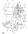
- a tester wears in the FIGS. 1 and 2 Overall, the reference numeral 10. It is used to test a cam-driven fuel injection system, in the present example of a pump-injector system 12, which, however, only in FIG. 1 is shown. First, its structure and function are explained.
- the pump-nozzle injection system 12 comprises a housing 14 with a nozzle tip 16 which projects into an injection chamber 18 of the test apparatus 10.
- a nozzle needle 20 is slidably received, which is acted upon by a spring 22 in a closed position.
- a pump of the pump-nozzle injection system 12 is designated by 24 and comprises a piston 26 which delimits a delivery space 28. This is connected to a pressure chamber 30 which is delimited by a pressure surface 32 formed on the nozzle needle 20 and acting in its opening direction.
- the delivery chamber 28 is further connected via a magnetic control valve 34 and a feed pump 36 with a fluid container 38, in which a test fluid is stored in the present case.
- test fluid is sucked out of the fluid container 38 into the delivery chamber 28 when the control valve 34 is open.
- the control valve 34 is closed, the test fluid enclosed in the delivery chamber 28 is compressed during a delivery stroke of the piston 26, which leads to a corresponding pressure increase in the pressure chamber 30. If the hydraulic force acting on the pressure surface 32 exceeds the force of the spring 22, the nozzle needle 20 opens and test fluid is injected from the nozzle tip 16 into the injection chamber 18, where it is collected and passed on.
- test apparatus 10 For testing the pump-nozzle injection system 12, the test apparatus 10 has two essential sub-apparatuses: an actuator 40 and a fixture 42. First to the latter:
- the fastening device 42 comprises a guide plate 44 with a plurality of mutually parallel guide grooves 46, of which, for reasons of clarity, only one carries a reference numeral.
- guide grooves 46 By means of these guide grooves 46, different attachment positions are defined for an adapter element designed as an adapter plate 48.
- the housing 14 of the pump-nozzle injection system 12 is fixed in a manner not shown here.
- the guide plate 44 is articulated in 50 to a stationary base 52 of the test apparatus 10. In order to prevent tilting of the guide plate 44 during operation, this is supported at its end remote from the joint 50 via a pendulum support 54 on a bearing block 56, which is also connected to the stationary base 52. On the bearing block 56 designed as a strain gauge 58 sensor is arranged, which detects a force acting on the bearing block 56 via the pendulum support 54 transverse force.
- the actuator 40 is constructed as follows.
- a drag lever 60 is pivotally mounted in 62 again on the stationary base 52.
- the pivot joint 62 is laterally spaced from a longitudinal axis 64 of the piston 26 of the pump-nozzle injection system 12.
- An arm 66 of the finger lever 60 extends to the piston 26 back.
- an intermediate element forming an intermediate plate 68 is fixed, in which a plurality of threaded holes 70 are present (for illustrative reasons, again only one provided with a reference numeral).
- the threaded bores 70 are spaced differently from the pivot axis of the finger lever 60 defined by the hinge 62.
- the ball head of the actuator 22 cooperates with a complementary recess (without reference numeral) in the piston 26 of the pump-nozzle injection system 12 together.
- a roller holder 74 with a roller 76 is arranged on this. This in turn cooperates with a cam 78 of a camshaft 80. This is driven by a drive motor, not shown here, for example an electric motor.
- a second arm 82 of the drag lever 60 is acted upon by a compression spring 84 which is clamped between the arm 82 and in turn the stationary base 52. In this way, the roller 76 is constantly pressed against the cam 78.
- the test apparatus 10 operates as follows: Upon rotation of the camshaft 80, the drag lever 60 is pivoted about its pivot axis 62. Due to the lever arm between the actuator 72 and the pivot axis defined by the hinge 62 (this lever arm is in FIG. 1 denoted by 86) results for each threaded bore 70 a certain stroke. This is at that threaded hole 70 in the in FIG. 1 the actuator 72 is screwed in, least. Accordingly, there is a comparatively small stroke of the piston 26. The reaction force which is introduced by the pressure build-up in the delivery chamber 28 via the housing 14 and the adapter plate 48 in the guide plate 44 is transmitted via the pendulum support 54 in the bearing block 56 and there from the strain gauge 58 recorded.
- the adapter plate 48 is simply mounted in other guide grooves 46 on the guide plate 44 and the actuator 72 is screwed into another of the threaded holes 70. If another pump-injector system 12 is to be tested, another adapter plate 48 is used. Possible, but not shown, is that the guide grooves are individualized, so that each type of fuel injection system is assigned a specific mounting position and thus a specific hub unmistakable. In an embodiment also not shown, moreover, the fastening device can be moved together with the actuator (without camshaft) in the longitudinal direction of the camshaft. The corresponding camshaft then has a plurality of different and juxtaposed cams, so that depending on the position of the actuator, the roller cooperates with another cam.
- the rotation angle sensor 82 On the camshaft 80, a rotation angle sensor 82 is provided.
- the rotation angle sensor 82 has a very high resolution. It has proven in practical experiments to be sufficient if the resolution of the rotation angle sensor is less than 0.1 degrees.
- a zero stroke H 0 of the cam 78 is in FIG. 1 also registered. If, for example, a solenoid valve of the fuel injection system to be tested is to be controlled at a stroke H 1 , then the hub H 1 can be assigned an angle of rotation ⁇ 1 to the camshaft 80. In this case, for the zero stroke H 0 , the angle of rotation ⁇ 0 is equal to 0.
- the hub H 1 or other strokes H i each have a rotational angle ⁇ 1 or ⁇ i of the camshaft 80.
- the solenoid valve of the fuel injection system to be tested can then be activated as a function of the angle of rotation ⁇ .
- the rotation angle sensor 82 is not shown.
- FIG. 3 a flow chart of a method according to the invention for adjusting a test device according to the invention is shown.
- the base circle of a cam 78 of a camshaft 80 is detected in a block 84.
- a further block 86 the camshaft 80 is rotated until a predetermined stroke H 1 is reached.
- the rotation angle ⁇ 1 associated with this stroke H 1 is detected and stored in a third block 88 on a storage medium.
- the blocks 86 and 88 are traversed so many times, until each test H; a rotation angle ⁇ i of the camshaft 80 is detected and stored.
- the test device can be delivered and used by the customer. Due to the individual assignment of the rotation angle ⁇ i to the test strokes H; Also possible manufacturing inaccuracies, for example, in the contour of the cam 78 can be eliminated, so that all delivered test devices have an identical accuracy.
- FIG. 4 a side view of a camshaft 80 with a cam 78 is shown.
- a reference signal of the angle sensor 82 is delivered 10 ° to 30 ° before reaching the zero stroke.
- the range within which advantageously the reference signal of the rotation angle sensor 82 is output is in FIG. 4 provided with the reference numeral 90.
Landscapes
- Engineering & Computer Science (AREA)
- Chemical & Material Sciences (AREA)
- Combustion & Propulsion (AREA)
- Mechanical Engineering (AREA)
- General Engineering & Computer Science (AREA)
- Fuel-Injection Apparatus (AREA)
Description
- Die Erfindung betrifft eine Prüfvorrichtung für ein nockengetriebenes Kraftstoff-Einspritzsystem, insbesondere ein Pumpe-Düse- oder Pumpe-Leitung-Düse-Einspritzsystem, nach dem Oberbegriff des Anspruchs 1.
- Bei modernen Dieselmotoren wird der Kraftstoff direkt von einem Kraftstoff-Einspritzsystem unter hohem Druck in den Brennraum eingespritzt. Dabei kommen verschiedene Typen von Kraftstoff-Einspritzsystemen zur Anwendung, beispielsweise Pumpe-Düse-Einspritzsysteme oder Pumpe-Leitung-Düse-Einspritzsysteme. Beide Kraftstoff-Einspritzsysteme werden am Motor selbst über eine Nockenwelle betätigt. Eine Nocke auf der Nockenwelle bewirkt über einen Hebel einen Hub eines Pumpenkolbens des Kraftstoff-Einspritzsystems. Dieser erzeugt an einer Düse des Kraftstoff-Einspritzsystems einen sehr hohen Druck, durch den eine Ventilnadel in eine geöffnete Stellung verdrängt und so Kraftstoff in einen Brennraum des Motors eingespritzt wird. Die Einspritzmenge wird über ein Magnetventil eingestellt, welches den Druckaufbau in dem Kraftstoff-Einspritzsystem steuert.
- Der Einspritzdruck und die Einspritzmenge sind unter anderem abhängig von der Form der Nocke und deren Hub. Unterschiedliche Kraftstoff-Einspritzsysteme weisen unterschiedliche Hübe und Nockenformen auf. Zum Teil werden auch identische Kraftstoff-Einspritzsysteme mit identischem Hub in unterschiedlichen Typen von Motoren mit unterschiedlichen Nocken betätigt.
- Zu Testzwecken und für die Qualitätskontrolle der oben beschriebenen nockengetriebenen Kraftstoff-Einspritzsysteme sind vom Markt her Prüfvorrichtungen bekannt. In eine solche Prüfvorrichtung wird ein nockengetriebenes Kraftstoff-Einspritzsystem eingebaut. Über eine Nockenwelle und einen Hebel wird der Kolben des Kraftstoff-Einspritzsystems beaufschlagt und hierdurch ein Betrieb simuliert.
- Um das Kraftstoff-Einspritzsystem auf einer Prüfvorrichtung prüfen zu können, muss die Betätigung des Einspritzsystems durch die Nocke der Prüfvorrichtung simuliert werden. Des Weiteren muss mit dem Erreichen eines vorgegebenen Hubs der Nocke ein Magnetventil im Einspritzsystem über ein zur Prüfvorrichtung gehörendes Steuergerät angesteuert werden.
- Die Ansteuerung des Magnetventils muss bei einem definierten Hub des Nockens erfolgen, um den richtigen Einspritzdruck und die richtige Einspritzmenge zu erzeugen. Da die Erfassung des Hubs aufwendiger ist als die Erfassung des Drehwinkels der Nockenwelle, wird üblicherweise die Ansteuerung des Magnetventils in Abhängigkeit eines vorgegebenen Drehwinkels der Nockenwelle durchgeführt. Um die Prüfvorrichtung an das zu prüfende Einspritzsystem anzupassen, wird bei auf dem Markt verfügbaren Prüfvorrichtungen ein Abgleich der Nocke durchgeführt. Dazu wird mit einer Messuhr der Grundkreis der Nocke ermittelt und die Messuhr auf Null gestellt. Dann wird die Nockenwelle solange in die Richtung gedreht, mit der sie auch während des Prüfvorgangs gedreht wird, bis ein vorgegebener Hub, der von der Form der Nocke abhängt, erreicht ist. Diesem vorgegebenen Hub ist ein Drehwinkel der Nockenwelle fest zugeordnet. Deshalb ist es möglich, nach Erreichen des vorgegebenen Hubs einen Geber der Prüfvorrichtung so relativ zur Nockenwelle zu verdrehen, dass genau bei diesem Hub ein Steuersignal vom Geber ausgegeben wird. Damit ist die Prüfvorrichtung zur Prüfung des zu prüfenden Einspritzsystems eingestellt und die Prüfung des Einspritzsystems kann vorgenommen werden. Nachteilig an diesem Verfahren ist, dass beim Wechseln des zu prüfenden Einspritzsystems die Prüfvorrichtung erneut eingestellt werden muss. Ursächlich hierfür ist es, dass verschiedene Typen von Einspritzsystemen einen anderen Hub und infolgedessen einen anderen Nockenwinkel als Startsignal für die Ansteuerung des Magnetventils in dem Einspritzsystem benötigen.
- Da die Einstellung der Prüfvorrichtung für jeden Typ von Einspritzsystemen erneut erfolgen muss, ist der Wechsel des zu prüfenden Einspritzsystems stets mit einem erheblichem Zeitaufwand verbunden und es können bei der Einstellung der Prüfvorrichtung Fehler auftreten.
- Aus der
US 2005/0150271 A1 ist eine Vorrichtung zum Kalibrieren eines Kraftstoffeinspritzsystems, umfassend eine Pumpeneinheit, ein Einspritzleitung und einer Einspritzdüse, bekannt. Das Kalibrieren erfolgt durch Verdrehen der Pumpeneinheit und die Verwendung verschieden dicker Ausgleichsscheiben (shims). - Diese Prüfvorrichtung ist nur bei einer bestimmten Bauart eines Kraftstoffeinspritzystems einsetzbar. Daher muss für jede Bauart eine gesonderte Vorrichtung angefertigt werden, was erhebliche Kosten verursacht.
- Der Erfindung liegt die Aufgabe zugrunde, ein Verfahren und ein zum Einstellen einer Prüfvorrichtung und eine verbesserte Prüfvorrichtung anzugeben, bei denen fehlerhafte Einstellungen vermieden werden können und bei denen der Wechsel des zu prüfenden Einspritzsystems einen geringeren Zeitaufwand für das Umrüsten der Prüfvorrichtung erfordert.
- Diese Aufgabe wird erfindungsgemäß bei einer Prüfvorrichtung für ein nockengetriebenes Kraftstoff-Einspritzsystem nach dem Oberbegriff des Anspruchs 1 durch die kennzeichnenden Merkmale des Anspruchs 1 gelöst.
- Durch den erfindungsgemäß beanspruchten Drehwinkelsensor ist es möglich, jedem Drehwinkel der Nockenwelle einen zugehörigen Hub der Nocke zuzuordnen. Da diese Zuordnung ausschließlich von der Form der Nocke abhängt, kann diese Zuordnung schon bei der Montage während der Herstellung der erfindungsgemäßen Prüfvorrichtung vorgenommen werden und abgespeichert werden. Bei der erfindungsgemäßen Prüfvorrichtung können ein Hebel, welcher die Steuerbewegungen der Nocken auf ein Pumpenelement des zu prüfenden Einspritzsystems überträgt, zusammen mit einer Befestigungsvorrichtung für das zu prüfende Kraftstoff-Einspritzsystem in axialer Richtung der Nockenwelle in unterschiedliche Betriebspositionen verschiebbar ist, wobei der Hebel in jeder Betriebsposition mit einer anderen Nocke zusammenarbeitet. Infolgedessen muss der Benutzer der erfindungsgemäßen Prüfvorrichtung die Prüfvorrichtung nicht mehr einstellen, bevor er ein Kraftstoffeinspritzsystem prüft.
- Dadurch wird erheblich Zeit beim Umrüsten der Prüfvorrichtung von einem Einspritzsystem auf ein anderes Einspritzsystem eingespart und es können Fehler durch falsche Einstellungen der Prüfvorrichtung vollständig vermieden werden.
- Selbstverständlich ist es auch möglich, die zum Prüfen verschiedener Typen von Einspritzsystemen erforderlichen Hübe der Nocke der Nockenwelle verschiedenen Drehwinkeln der Nockenwelle zuzuordnen. Auch diese Zuordnungen können schon bei der Herstellung und der Montage der erfindungsgemäßen Prüfvorrichtung vorgenommen werden und in Form einer Tabelle in dem Speicherelement der Prüfvorrichtung abgelegt werden. Es kann auch, falls gewünscht, die gesamte Kontur des Nockens in Abhängigkeit des Drehwinkels der Nockenwelle abgespeichert werden, so dass Fertigungstoleranzen bei der Herstellung der Nocke vollständig eliminiert werden.
- Die erfindungsgemäßen Vorteile werden bei der Durchführung eines erfindungsgemäßen Verfahrens, zum Einstellen einer Prüfvorrichtung für ein nockengetriebenes Kraftstoff-Einspritzsystem gemäß Anspruch 4 erreicht
- Es hat sich weiter als vorteilhaft erwiesen, wenn ein Referenzsignal des Winkelsensors vor dem Erreichen des Nullhubs der Nockenwelle abgegeben wird.
- Insbesondere hat es sich als vorteilhaft erwiesen, wenn das Referenzsignal zwischen 30° und 10° vor Erreichen des Nullhubs der Nockenwelle abgegeben wird.
- Selbstverständlich ist es auch möglich, die zu verschiedenen Einspritzsystemen gehörenden verschiedenen Hübe bei denen ein Magnetventil der Kraftstoff-Einspritzsysteme angesteuert werden soll, nacheinander zu erfassen und die zugehörigen Drehwinkel der Nockenwelle zu erfassen und abzuspeichern. Dadurch ist es möglich, schon bei der Herstellung der erfindungsgemäßen Prüfvorrichtung zu allen Hüben, die während des Betriebs der Prüfvorrichtung erforderlich sind, die zugehörigen Drehwinkel der Nockenwelle zu erfassen und abzuspeichern.
- Im Ergebnis ist mit dem erfindungsgemäßen Verfahren nicht nur eine erhebliche Zeitersparnis beim Umrüsten der Prüfvorrichtung von einem Kraftstoff-Einspritzsystem auf ein anderes Kraftstoff-Einspritzsystem verbunden, sondern die Möglichkeit von fehlerhaften Einstellungen der Prüfvorrichtung beim Wechsel des zu prüfenden Kraftstoff-Einspritzsystems wird vollständig eliminiert.
- Nachfolgend wird ein besonders bevorzugtes Ausführungsbeispiel der vorliegenden Erfindung unter Bezugnahme auf die beiliegende Zeichnung näher erläutert. In der Zeichnung zeigen:
- Figur 1
- eine schematische und teilweise geschnittene Darstellung einer Prüfvorrichtung für ein nockengetriebenes Kraftstoff-Einspritzsystem;
- Figur 2
- eine perspektivische, ebenfalls zum Teil geschnittene und stärker detaillierte Darstellung der Prüfvorrichtung von
Figur 1 ; - Figur 3:
- ein Ablaufdiagramm eines erfindungsgemäßen Verfahrens; und
- Figur 4:
- die Einstellung des Referenzsignals des Drehwinkelsensors relativ zum Nullhub der Nocke.
- Eine Prüfvorrichtung trägt in den
Figuren 1 und2 insgesamt das Bezugszeichen 10. Sie dient zum Prüfen eines nockengetriebenen Kraftstoff-Einspritzsystems, im vorliegenden Beispiel eines Pumpe-Düse-Einspritzsystems 12, welches jedoch nur inFigur 1 gezeigt ist. Zunächst sei dessen Aufbau und Funktion erläutert. - Das Pumpe-Düse-Einspritzsystem 12 umfasst ein Gehäuse 14 mit einer Düsenspitze 16, die in eine Einspritzkammer 18 der Prüfvorrichtung 10 hineinragt. In dem Gehäuse 14 ist eine Düsennadel 20 verschieblich aufgenommen, die von einer Feder 22 in eine geschlossene Position beaufschlagt wird.
- Eine Pumpe des Pumpe-Düse-Einspritzsystems 12 ist mit 24 bezeichnet und umfasst einen Kolben 26, der einen Förderraum 28 begrenzt. Dieser ist mit einem Druckraum 30 verbunden, der von einer an der Düsennadel 20 ausgebildeten und in deren Öffnungsrichtung wirkenden Druckfläche 32 begrenzt wird. Der Förderraum 28 ist ferner über ein magnetisches Steuerventil 34 und eine Vorförderpumpe 36 mit einem Fluidbehälter 38 verbindbar, in dem im vorliegenden Fall ein Prüffluid bevorratet ist.
- Bei einem Saughub des Kolbens 26 wird bei geöffnetem Steuerventil 34 Prüffluid aus dem Fluidbehälter 38 in den Förderraum 28 angesaugt. Bei geschlossenem Steuerventil 34 wird bei einem Förderhub des Kolbens 26 das im Förderraum 28 eingeschlossene Prüffluid komprimiert, was zu einer entsprechenden Druckerhöhung im Druckraum 30 führt. Übersteigt die an der Druckfläche 32 angreifende hydraulische Kraft die Kraft der Feder 22, öffnet die Düsennadel 20, und Prüffluid wird von der Düsenspitze 16 in die Einspritzkammer 18 eingespritzt, wo es gesammelt und weitergeleitet wird.
- Für die Prüfung des Pumpe-Düse-Einspritzsystems 12 verfügt die Prüfvorrichtung 10 über zwei wesentliche Teilvorrichtungen: Eine Betätigungsvorrichtung 40 und eine Befestigungsvorrichtung 42. Zunächst zu letzterer:
- Die Befestigungsvorrichtung 42 umfasst eine Führungsplatte 44 mit mehreren parallel zueinander angeordneten Führungsnuten 46, von denen aus Gründen der Übersichtlichkeit nur eine ein Bezugszeichen trägt. Durch diese Führungsnuten 46 werden unterschiedliche Befestigungspositionen für ein als Adapterplatte 48 ausgebildetes Adapterelement definiert. An dieser Adapterplatte 48 ist wiederum auf hier nicht näher dargestellte Art und Weise das Gehäuse 14 des Pumpe-Düse-Einspritzsystems 12 befestigt.
- Die Führungsplatte 44 ist in 50 an einer stationären Basis 52 der Prüfvorrichtung 10 gelenkig gelagert. Um im Betrieb ein Kippen der Führungsplatte 44 zu verhindern, stützt sich diese an ihrem vom Gelenk 50 beabstandeten Ende über eine Pendelstütze 54 an einem Lagerbock 56 ab, der ebenfalls mit der stationären Basis 52 verbunden ist. Am Lagerbock 56 ist ein als Dehnmessstreifen 58 ausgebildeter Sensor angeordnet, der eine auf den Lagerbock 56 über die Pendelstütze 54 einwirkende Querkraft erfasst.
- Die Betätigungsvorrichtung 40 ist folgendermaßen aufgebaut. Ein Schlepphebel 60 ist in 62 wieder an der stationären Basis 52 schwenkbar gelagert. Das Schwenkgelenk 62 ist dabei seitlich beabstandet von einer Längsachse 64 des Kolbens 26 des Pumpe-Düse-Einspritzsystems 12. Ein Arm 66 des Schlepphebels 60 erstreckt sich zum Kolben 26 hin. An ihm ist eine ein Zwischenelement bildende Zwischenplatte 68 befestigt, in der mehrere Gewindebohrungen 70 vorhanden sind (aus Darstellungsgründen ist wieder nur eine mit einem Bezugszeichen versehen). Diese bilden Befestigungspositionen für ein mit einem Kugelkopf versehenes Betätigungselement 72. Wie aus
Figur 1 ersichtlich ist, sind die Gewindebohrungen 70 von der durch das Gelenk 62 definierten Schwenkachse des Schlepphebels 60 unterschiedlich beabstandet. Der Kugelkopf des Betätigungselement 22 arbeitet mit einer komplementären Ausnehmung (ohne Bezugszeichen) im Kolben 26 des Pumpe-Düse-Einspritzsystems 12 zusammen. - Auf der vom Kolben 26 abgewandten Seite des Arms 66 ist an diesem ein Rollenhalter 74 mit einer Rolle 76 angeordnet. Diese arbeitet wiederum mit einer Nocke 78 einer Nockenwelle 80 zusammen. Diese wird von einem hier nicht dargestellten Antriebsmotor, beispielsweise einem Elektromotor, angetrieben. Ein zweiter Arm 82 des Schlepphebels 60 wird von einer Druckfeder 84 beaufschlagt, die zwischen dem Arm 82 und wiederum der stationären Basis 52 verspannt ist. Auf diese Weise wird die Rolle 76 ständig gegen die Nocke 78 gedrückt.
- Die Prüfvorrichtung 10 arbeitet folgendermaßen: Bei einer Drehung der Nockenwelle 80 wird der Schlepphebel 60 um seine Schwenkachse 62 verschwenkt. Aufgrund des Hebelarms zwischen dem Betätigungselement 72 und der durch das Gelenk 62 definierten Schwenkachse (dieser Hebelarm ist in
Figur 1 mit 86 bezeichnet) ergibt sich für jede Gewindebohrung 70 ein bestimmter Hub. Dieser ist bei jener Gewindebohrung 70, in der inFigur 1 das Betätigungselement 72 eingeschraubt ist, am geringsten. Entsprechend ergibt sich ein vergleichsweise geringer Hub des Kolbens 26. Die Reaktionskraft, die durch den Druckaufbau im Förderraum 28 über das Gehäuse 14 und die Adapterplatte 48 in die Führungsplatte 44 eingeleitet wird, wird über die Pendelstütze 54 in den Lagerbock 56 übertragen und dort vom Dehnmessstreifen 58 erfasst. - Soll das gleiche Pumpe-Düse-Einspritzsystem 12 mit größerem Hub getestet werden, wird die Adapterplatte 48 einfach in anderen Führungsnuten 46 an der Führungsplatte 44 befestigt und das Betätigungselement 72 in eine andere der Gewindebohrungen 70 eingeschraubt. Soll ein anderes Pumpe-Düse-Einspritzsystem 12 getestet werden, wird eine andere Adapterplatte 48 verwendet. Möglich, jedoch nicht dargestellt, ist es, dass die Führungsnuten individualisiert sind, so dass jedem Typ von Kraftstoff-Einspritzsystem eine bestimmte Befestigungsposition und damit auch ein bestimmter Hub unverwechselbar zugeordnet ist. In einem ebenfalls nicht dargestellten Ausführungsbeispiel kann darüber hinaus die Befestigungsvorrichtung zusammen mit der Betätigungsvorrichtung (ohne Nockenwelle) in Längsrichtung der Nockenwelle verschoben werden. Die entsprechende Nockenwelle verfügt dann über eine Mehrzahl unterschiedlicher und nebeneinander angeordneter Nocken, so dass je nach Position der Betätigungseinrichtung die Rolle mit einer anderen Nocke zusammenarbeitet.
- An der Nockenwelle 80 ist ein Drehwinkelsensor 82 vorgesehen. Der Drehwinkelsensor 82 hat eine sehr hohe Auflösung. Es hat sich bei praktischen Versuchen als ausreichend erwiesen, wenn die Auflösung des Drehwinkelsensors kleiner als 0,1 Grad ist.
- Ein Nullhub H0 der Nocke 78 ist in
Figur 1 ebenfalls eingetragen. Wenn nun beispielsweise ein Magnetventil des zu prüfenden Kraftstoff-Einspritzsystems bei einem Hub H1 angesteuert werden soll, so kann dem Hub H1 ein Drehwinkel ϕ1 der Nockenwelle 80 zugeordnet werden. Dabei gilt für den Nullhub H0, dass der Drehwinkel ϕ0 gleich 0 ist. - Somit ist es möglich, dem Hub H1 oder auch anderen Hübe Hi jeweils einen Drehwinkel ϕ1 oder ϕi der Nockenwelle 80 zuzuordnen. Bei der Durchführung einer Prüfung eines Kraftstoff Einspritzsystems kann dann in Abhängigkeit des Drehwinkels ϕ das Magnetventil des zu prüfenden Kraftstoff-Einspritzsytems angesteuert werden. In
Figur 2 ist der Drehwinkelsensor 82 nicht dargestellt. - In
Figur 3 ist ein Ablaufdiagramm eines erfindungsgemäßen Verfahrens zur Einstellung einer erfindungsgemäßen Prüfvorrichtung dargestellt. - Nach einem Startblock wird in einem Block 84 der Grundkreis einer Nocke 78 einer Nockenwelle 80 erfasst. Am Grundkreis hat die Nocke 78 einen Hub H0 = 0.
- In einem weiteren Block 86 wird die Nockenwelle 80 so weit gedreht bis ein vorgegebener Hub H1 erreicht wird. Der zu diesem Hub H1 gehörende Drehwinkel ϕ1 wird erfasst und in einem dritten Block 88 auf einem Speichermedium abgespeichert.
- Falls zu verschiedenen Hüben H; die zugehörigen Drehwinkel ϕi der Nockenwelle 80 erfasst werden sollen, werden die Blöcke 86 und 88 so oft durchlaufen, bis zu jedem Prüfhub H; ein Drehwinkel ϕi der Nockenwelle 80 erfasst und abgespeichert ist. Mit diesen abgespeicherten Werten, die für jede Prüfvorrichtung nach erfolgter Montage individuell erfasst werden, kann die Prüfvorrichtung ausgeliefert und beim Kunden eingesetzt werden. Durch die individuelle Zuordnung der Drehwinkel ϕi zu den Prüfhüben H; können auch eventuelle Fertigungsungenauigkeiten, beispielsweise in der Kontur der Nocke 78 eliminiert werden, so dass alle ausgelieferten Prüfvorrichtungen eine identische Genauigkeit aufweisen.
- In
Figur 4 ist eine Seitenansicht einer Nockenwelle 80 mit einer Nocke 78 dargestellt. Der Nullhub H0 ist bei einem Winkel ϕ0 = 0° erreicht. - Es hat sich als vorteilhaft erwiesen, wenn ein Referenzsignal des nicht dargestellten Winkelsensors 82 10° bis 30° vor dem Erreichen des Nullhubs abgegeben wird. Der Bereich, innerhalb dessen vorteilhafterweise das Referenzsignal des Drehwinkelsensors 82 abgegeben wird, ist in
Figur 4 mit dem Bezugszeichen 90 versehen.
Claims (9)
- Prüfvorrichtung (10) für ein nockengetriebenes Kraftstoff-Einspritzsystem (12), insbesondere ein Pumpe-Düse-Einspritzsystem oder ein Pumpe-Leitung-Düse-Einspritzsystem, mit einer Nockenwelle (80), die mittelbar auf einen Kolben (26) des Kraftstoff-Einspitzsystems (12) wirken kann, wobei mindestens mittelbar an der Nockenwelle (80) ein Drehwinkelsensor (82) angeordnet ist, dadurch gekennzeichnet, dass im Betrieb die Nockenwelle (80) über einen Hebel (60) auf den Kolben (26) wirken kann, dass die Nockenwelle (80) eine Mehrzahl nebeneinander angeordneter unterschiedlicher Nocken (78) aufweist, dass der Hebel (60) zusammen mit einer Befestigungsvorrichtung für das Kraftstoff-Einspritzsystem (12) in axialer Richtung der Nockenwelle (80) in unterschiedliche Betriebspositionen verschiebbar ist, und dass der Hebel (60) in jeder Betriebsposition mit einer anderen Nocke (78) zusammenarbeitet.
- Prüfvorrichtung (10) nach Anspruch 1, dadurch gekennzeichnet, dass die Prüfvorrichtung ein Speicherelement umfasst, und dass in dem Speicherelement mindestens einem Drehwinkel (ϕ1) der Nockenwelle (80) ein Hub (H1) des Nockens (78) der Nockenwelle (80) zugeordnet ist.
- Prüfvorrichtung (10) nach Anspruch 2, dadurch gekennzeichnet, dass das Speicherelement als ein random access memory (RAM), ein read only memory (ROM), ein flash-Speicher, ein optisches Speichermedium oder ein magnetisches Speichermedium ausgebildet ist.
- Verfahren zum Einstellen einer Prüfvorrichtung für ein nockengetriebenes Kraftstoff-Einspritzsystem (12), wobei die Prüfeinrichtung eine Nockenwelle (80) umfasst, die Nockenwelle (80) über einen Hebel (60) auf einen Kolben (26) des Kraftstoff-Einspritzsystems (12) wirken kann, wobei mindestens mittelbar an der Nockenwelle (80) ein Drehwinkelsensor (82) angeordnet ist, dadurch gekennzeichnet, daß die Nockenwelle (80) eine Mehrzahl nebeneinander angeordneter unterschiedlicher Nocken (78) aufweist, wobei der Hebel (60) zusammen mit einer Befestigungsvorrichtung für die Kraftstoff-Einspritzsystems (12) in axialer Richtung der Nockenwelle (80) in unterschiedliche Betriebspositionen verschiebbar ist und wobei der Hebel (60) in jeder Betriebsposition mit einer anderen Nocke (78) zusammenarbeitet, gekennzeichnet, durch folgende Verfahrensschritte:- Verschieben des Hebel (60) zusammen mit der Befestigungsvorrichtung in axialer Richtung der Nockenwelle (80) in eine gewünschte Betriebsposition- Erfassen eines Grundkreises (Hub = H0) mindestens einer Nocke (78) einer Nockenwelle (80),- Verdrehen der Nockenwelle (80) bis ein vorgegebener Hub (H1) der mindestens einen Nocke (78) erreicht ist,- Erfassen des mit dem vorgegeben Hub (H1) der mindestens einen Nocke (78) korrelierenden Drehwinkels (ϕ1) der Nockenwelle (80) und- Abspeichern von Drehwinkel (ϕ1) und Hub (H1) auf einem Speichermedium.
- Verfahren nach Anspruch 4, dadurch gekennzeichnet, dass ein Referenzsignal des Winkelsensors (82) vor dem Erreichen des Nullhubs (H0) der Nockenwelle (80) abgegeben wird.
- Verfahren nach Anspruch 5, dadurch gekennzeichnet, dass das Referenzsignal des Drehwinkelsensors (82) zwischen 30° und 10° vor dem Erreichen des Nullhubs (H0) der Nockenwelle (80) abgegeben wird.
- Verfahren nach einem der Ansprüche 4 bis 6, dadurch gekennzeichnet, dass für verschiedene Hübe (Hi) der mindestens einen Nocke (78) die mit den verschiedenen Hüben (Hi) korrelierenden Drehwinkel (ϕi) der Nockenwelle (80) erfasst und auf einem Speichermedium abgespeichert werden.
- Computerprogramm, das auf einem Rechengerät, insbesondere einem Steuergerät () zur Steuerung einer Prüfvorrichtung für ein nockengetriebenes Kraftstoff-Einspritzsystem (12) ablauffähig ist, dadurch gekennzeichnet, dass das Computerprogramm zur Durchführung eines Verfahrens nach einem der Ansprüche 4 bis 6 programmiert ist, wenn das Computerprogramm auf dem Rechengerät abläuft.
- Computerprogramm nach Anspruch 8, dadurch gekennzeichnet, dass das Computerprogramm auf einem Speicherelement, insbesondere auf einem dem Rechengerät zugeordneten Speicherelement, abgespeichert ist, wobei das Speicherelement als ein random access memory (RAM), ein read only memory (ROM), ein flash-Speicher, ein optisches Speichermedium oder ein magnetisches Speichermedium ausgebildet ist.
Applications Claiming Priority (1)
| Application Number | Priority Date | Filing Date | Title |
|---|---|---|---|
| DE200610041072 DE102006041072A1 (de) | 2006-09-01 | 2006-09-01 | Verfahren zum Justieren einer Prüfvorrichtung für ein nockengetriebenes Kraftstoff-Einspritzsystem, insbesondere ein Pumpe-Düse-oder Pumpe-Leitung-Düse-Einspritzsystem |
Publications (3)
| Publication Number | Publication Date |
|---|---|
| EP1895151A2 EP1895151A2 (de) | 2008-03-05 |
| EP1895151A3 EP1895151A3 (de) | 2009-06-17 |
| EP1895151B1 true EP1895151B1 (de) | 2015-10-21 |
Family
ID=38421512
Family Applications (1)
| Application Number | Title | Priority Date | Filing Date |
|---|---|---|---|
| EP07112117.2A Active EP1895151B1 (de) | 2006-09-01 | 2007-07-10 | Prüfvorrichtung und Verfahren zum Justieren einer Prüfvorrichtung für ein nockengetriebenes Kraftstoff-Einspritzsystem, insbesondere ein Pumpe-Düse- oder Pumpe-Leitung-Düse-Einspritzsystem. |
Country Status (2)
| Country | Link |
|---|---|
| EP (1) | EP1895151B1 (de) |
| DE (1) | DE102006041072A1 (de) |
Families Citing this family (2)
| Publication number | Priority date | Publication date | Assignee | Title |
|---|---|---|---|---|
| DE102013221242A1 (de) * | 2013-10-21 | 2015-04-23 | Volkswagen Aktiengesellschaft | Verfahren zum Betreiben eines Verbrennungsmotors |
| KR102460186B1 (ko) * | 2022-08-24 | 2022-10-31 | (주)한미유압기계 | 마이크로 파일럿 부스터 인젝터 밸브와 슬라이드 밸브의 테스트가 가능한 선박 엔진용 연료분사밸브 검사 장치 |
Citations (1)
| Publication number | Priority date | Publication date | Assignee | Title |
|---|---|---|---|---|
| US20050150271A1 (en) * | 2002-03-19 | 2005-07-14 | Klopfer Kenneth H. | System for calibrating an integrated injection nozzle and injection pump |
Family Cites Families (3)
| Publication number | Priority date | Publication date | Assignee | Title |
|---|---|---|---|---|
| JP3818607B2 (ja) * | 1997-01-27 | 2006-09-06 | 株式会社小松製作所 | カム駆動式の電子制御ユニットインジェクタの制御装置及びその制御方法 |
| DE10146772C2 (de) * | 2001-09-22 | 2003-09-25 | Orange Gmbh | Messvorrichtung zum Messen des Kolbenhubes einer Kraftstoffeinspritzpumpe |
| JP4111956B2 (ja) * | 2005-01-14 | 2008-07-02 | 三菱電機株式会社 | 内燃機関の燃料供給装置 |
-
2006
- 2006-09-01 DE DE200610041072 patent/DE102006041072A1/de not_active Withdrawn
-
2007
- 2007-07-10 EP EP07112117.2A patent/EP1895151B1/de active Active
Patent Citations (1)
| Publication number | Priority date | Publication date | Assignee | Title |
|---|---|---|---|---|
| US20050150271A1 (en) * | 2002-03-19 | 2005-07-14 | Klopfer Kenneth H. | System for calibrating an integrated injection nozzle and injection pump |
Also Published As
| Publication number | Publication date |
|---|---|
| EP1895151A3 (de) | 2009-06-17 |
| DE102006041072A1 (de) | 2008-03-06 |
| EP1895151A2 (de) | 2008-03-05 |
Similar Documents
| Publication | Publication Date | Title |
|---|---|---|
| EP1520097B1 (de) | Einrichtung zur dämpfung des nadelhubes an kraftstoffinjektoren | |
| DE102008042412A1 (de) | Steuergerät für ein Druckspeicherkraftstoffeinspritzsystem | |
| DE112009000172T5 (de) | Kraftstoffinjektor und Montageverfahren dafür | |
| DE69923108T2 (de) | Brennstoffsystem und Pumpe zur Anwendung in einem solchen System | |
| DE2935851A1 (de) | Treibstoffinjektor | |
| DE2137832C2 (de) | Einrichtung zum Einspritzen von Kraftstoff in eine Brennkraftmaschine | |
| EP1103718B1 (de) | Leerhubeinstellung zwischen einem Aktor und einem Übertragungselement eines Ventils in einem Kraftstoffinjektor | |
| DE3420345C2 (de) | ||
| DE3600113A1 (de) | Kraftstoff-einspritzeinrichtung fuer einen verbrennungsmotor | |
| DE10317610A1 (de) | Kraftstoffeinspritzvorrichtung | |
| EP1895151A2 (de) | Verfahren zum Justieren einer Prüfvorrichtung für ein nockengetriebenes Kraftstoff-Einspritzsystem, insbesondere ein Pumpe-Düse- oder Pumpe-Leitung-Düse-Einspritzsystem. | |
| EP1601945A1 (de) | Verfahren, vorrichtung und computerprogramm zum messen der leckage von einspritzsystemen, insbesondere für brennkraftmaschinen von kraftfahrzeugen | |
| DE102014007963A1 (de) | Verfahren zum Betreiben einer Brennkraftmaschine und Motorsteuergerät | |
| EP2612018A1 (de) | Verfahren und vorrichtung zum einstellen eines leerhubs eines stellantriebs eines einspritzventils und injektorbaugruppe | |
| DE3801929C2 (de) | Kraftstoffeinspritzeinrichtung | |
| EP1969226B1 (de) | Prüfvorrichtung für ein nockengetriebenes kraftstoff-einspritzsystem, insbesondere ein pumpe-düse- oder pumpe-leitung-düse-einspritzsystem | |
| DE19940558C2 (de) | Vorrichtung zum Verzögern des Auslenkens der Düsennadel eines Kraftstoffeinspritzventils | |
| EP3071805A1 (de) | Hydraulischer ventiltrieb eines verbrennungsmotors | |
| DE10307002A1 (de) | Kraftstoffeinspritzdüse und Pumpe-Düse-Einheit | |
| DE102004022641B4 (de) | Treibstoffförderpumpe einer Brennkraftmaschine | |
| WO2009156205A1 (de) | Abstützkörper, rückschlagventil sowie kraftstoff-hochdruckpumpe | |
| DE3310030C2 (de) | Kraftstoffeinspritzvorrichtung für eine Brennkraftmaschine | |
| EP1573197B1 (de) | Pumpe-düse-einheit und verfahren zur einstellung des öffnungsdruckes derselben | |
| DE102007033889A1 (de) | Kraftstoffpumpe für ein Einspritzsystem einer Brennkraftmaschine | |
| DE3318010A1 (de) | Einspritzeinrichtung fuer eine brennkraftmaschine |
Legal Events
| Date | Code | Title | Description |
|---|---|---|---|
| PUAI | Public reference made under article 153(3) epc to a published international application that has entered the european phase |
Free format text: ORIGINAL CODE: 0009012 |
|
| AK | Designated contracting states |
Kind code of ref document: A2 Designated state(s): AT BE BG CH CY CZ DE DK EE ES FI FR GB GR HU IE IS IT LI LT LU LV MC MT NL PL PT RO SE SI SK TR |
|
| AX | Request for extension of the european patent |
Extension state: AL BA HR MK YU |
|
| PUAL | Search report despatched |
Free format text: ORIGINAL CODE: 0009013 |
|
| AK | Designated contracting states |
Kind code of ref document: A3 Designated state(s): AT BE BG CH CY CZ DE DK EE ES FI FR GB GR HU IE IS IT LI LT LU LV MC MT NL PL PT RO SE SI SK TR |
|
| AX | Request for extension of the european patent |
Extension state: AL BA HR MK RS |
|
| 17P | Request for examination filed |
Effective date: 20091217 |
|
| 17Q | First examination report despatched |
Effective date: 20100121 |
|
| AKX | Designation fees paid |
Designated state(s): AT BE BG CH CY CZ DE DK EE ES FI FR GB GR HU IE IS IT LI LT LU LV MC MT NL PL PT RO SE SI SK TR |
|
| REG | Reference to a national code |
Ref country code: DE Ref legal event code: R079 Ref document number: 502007014332 Country of ref document: DE Free format text: PREVIOUS MAIN CLASS: F02M0057020000 Ipc: F02M0065000000 |
|
| RIC1 | Information provided on ipc code assigned before grant |
Ipc: F02M 57/02 20060101ALI20150320BHEP Ipc: F02M 65/00 20060101AFI20150320BHEP |
|
| GRAP | Despatch of communication of intention to grant a patent |
Free format text: ORIGINAL CODE: EPIDOSNIGR1 |
|
| INTG | Intention to grant announced |
Effective date: 20150730 |
|
| GRAS | Grant fee paid |
Free format text: ORIGINAL CODE: EPIDOSNIGR3 |
|
| GRAA | (expected) grant |
Free format text: ORIGINAL CODE: 0009210 |
|
| AK | Designated contracting states |
Kind code of ref document: B1 Designated state(s): AT BE BG CH CY CZ DE DK EE ES FI FR GB GR HU IE IS IT LI LT LU LV MC MT NL PL PT RO SE SI SK TR |
|
| REG | Reference to a national code |
Ref country code: GB Ref legal event code: FG4D Free format text: NOT ENGLISH Ref country code: NL Ref legal event code: MP Effective date: 20151021 |
|
| REG | Reference to a national code |
Ref country code: CH Ref legal event code: EP |
|
| REG | Reference to a national code |
Ref country code: AT Ref legal event code: REF Ref document number: 756780 Country of ref document: AT Kind code of ref document: T Effective date: 20151115 |
|
| REG | Reference to a national code |
Ref country code: IE Ref legal event code: FG4D Free format text: LANGUAGE OF EP DOCUMENT: GERMAN |
|
| REG | Reference to a national code |
Ref country code: DE Ref legal event code: R096 Ref document number: 502007014332 Country of ref document: DE |
|
| REG | Reference to a national code |
Ref country code: LT Ref legal event code: MG4D |
|
| PG25 | Lapsed in a contracting state [announced via postgrant information from national office to epo] |
Ref country code: NL Free format text: LAPSE BECAUSE OF FAILURE TO SUBMIT A TRANSLATION OF THE DESCRIPTION OR TO PAY THE FEE WITHIN THE PRESCRIBED TIME-LIMIT Effective date: 20151021 Ref country code: IS Free format text: LAPSE BECAUSE OF FAILURE TO SUBMIT A TRANSLATION OF THE DESCRIPTION OR TO PAY THE FEE WITHIN THE PRESCRIBED TIME-LIMIT Effective date: 20160221 Ref country code: ES Free format text: LAPSE BECAUSE OF FAILURE TO SUBMIT A TRANSLATION OF THE DESCRIPTION OR TO PAY THE FEE WITHIN THE PRESCRIBED TIME-LIMIT Effective date: 20151021 Ref country code: LT Free format text: LAPSE BECAUSE OF FAILURE TO SUBMIT A TRANSLATION OF THE DESCRIPTION OR TO PAY THE FEE WITHIN THE PRESCRIBED TIME-LIMIT Effective date: 20151021 |
|
| PG25 | Lapsed in a contracting state [announced via postgrant information from national office to epo] |
Ref country code: LV Free format text: LAPSE BECAUSE OF FAILURE TO SUBMIT A TRANSLATION OF THE DESCRIPTION OR TO PAY THE FEE WITHIN THE PRESCRIBED TIME-LIMIT Effective date: 20151021 Ref country code: PT Free format text: LAPSE BECAUSE OF FAILURE TO SUBMIT A TRANSLATION OF THE DESCRIPTION OR TO PAY THE FEE WITHIN THE PRESCRIBED TIME-LIMIT Effective date: 20160222 Ref country code: PL Free format text: LAPSE BECAUSE OF FAILURE TO SUBMIT A TRANSLATION OF THE DESCRIPTION OR TO PAY THE FEE WITHIN THE PRESCRIBED TIME-LIMIT Effective date: 20151021 Ref country code: GR Free format text: LAPSE BECAUSE OF FAILURE TO SUBMIT A TRANSLATION OF THE DESCRIPTION OR TO PAY THE FEE WITHIN THE PRESCRIBED TIME-LIMIT Effective date: 20160122 Ref country code: FI Free format text: LAPSE BECAUSE OF FAILURE TO SUBMIT A TRANSLATION OF THE DESCRIPTION OR TO PAY THE FEE WITHIN THE PRESCRIBED TIME-LIMIT Effective date: 20151021 Ref country code: SE Free format text: LAPSE BECAUSE OF FAILURE TO SUBMIT A TRANSLATION OF THE DESCRIPTION OR TO PAY THE FEE WITHIN THE PRESCRIBED TIME-LIMIT Effective date: 20151021 |
|
| REG | Reference to a national code |
Ref country code: DE Ref legal event code: R097 Ref document number: 502007014332 Country of ref document: DE |
|
| PG25 | Lapsed in a contracting state [announced via postgrant information from national office to epo] |
Ref country code: CZ Free format text: LAPSE BECAUSE OF FAILURE TO SUBMIT A TRANSLATION OF THE DESCRIPTION OR TO PAY THE FEE WITHIN THE PRESCRIBED TIME-LIMIT Effective date: 20151021 |
|
| PLBE | No opposition filed within time limit |
Free format text: ORIGINAL CODE: 0009261 |
|
| STAA | Information on the status of an ep patent application or granted ep patent |
Free format text: STATUS: NO OPPOSITION FILED WITHIN TIME LIMIT |
|
| PG25 | Lapsed in a contracting state [announced via postgrant information from national office to epo] |
Ref country code: DK Free format text: LAPSE BECAUSE OF FAILURE TO SUBMIT A TRANSLATION OF THE DESCRIPTION OR TO PAY THE FEE WITHIN THE PRESCRIBED TIME-LIMIT Effective date: 20151021 Ref country code: RO Free format text: LAPSE BECAUSE OF FAILURE TO SUBMIT A TRANSLATION OF THE DESCRIPTION OR TO PAY THE FEE WITHIN THE PRESCRIBED TIME-LIMIT Effective date: 20151021 Ref country code: SK Free format text: LAPSE BECAUSE OF FAILURE TO SUBMIT A TRANSLATION OF THE DESCRIPTION OR TO PAY THE FEE WITHIN THE PRESCRIBED TIME-LIMIT Effective date: 20151021 Ref country code: EE Free format text: LAPSE BECAUSE OF FAILURE TO SUBMIT A TRANSLATION OF THE DESCRIPTION OR TO PAY THE FEE WITHIN THE PRESCRIBED TIME-LIMIT Effective date: 20151021 |
|
| 26N | No opposition filed |
Effective date: 20160722 |
|
| PG25 | Lapsed in a contracting state [announced via postgrant information from national office to epo] |
Ref country code: SI Free format text: LAPSE BECAUSE OF FAILURE TO SUBMIT A TRANSLATION OF THE DESCRIPTION OR TO PAY THE FEE WITHIN THE PRESCRIBED TIME-LIMIT Effective date: 20151021 |
|
| PG25 | Lapsed in a contracting state [announced via postgrant information from national office to epo] |
Ref country code: BE Free format text: LAPSE BECAUSE OF NON-PAYMENT OF DUE FEES Effective date: 20160731 |
|
| REG | Reference to a national code |
Ref country code: CH Ref legal event code: PL |
|
| PG25 | Lapsed in a contracting state [announced via postgrant information from national office to epo] |
Ref country code: MC Free format text: LAPSE BECAUSE OF FAILURE TO SUBMIT A TRANSLATION OF THE DESCRIPTION OR TO PAY THE FEE WITHIN THE PRESCRIBED TIME-LIMIT Effective date: 20151021 |
|
| PG25 | Lapsed in a contracting state [announced via postgrant information from national office to epo] |
Ref country code: LI Free format text: LAPSE BECAUSE OF NON-PAYMENT OF DUE FEES Effective date: 20160731 Ref country code: CH Free format text: LAPSE BECAUSE OF NON-PAYMENT OF DUE FEES Effective date: 20160731 Ref country code: FR Free format text: LAPSE BECAUSE OF NON-PAYMENT OF DUE FEES Effective date: 20160801 |
|
| REG | Reference to a national code |
Ref country code: FR Ref legal event code: ST Effective date: 20170331 |
|
| REG | Reference to a national code |
Ref country code: IE Ref legal event code: MM4A |
|
| PG25 | Lapsed in a contracting state [announced via postgrant information from national office to epo] |
Ref country code: IE Free format text: LAPSE BECAUSE OF NON-PAYMENT OF DUE FEES Effective date: 20160710 |
|
| PG25 | Lapsed in a contracting state [announced via postgrant information from national office to epo] |
Ref country code: LU Free format text: LAPSE BECAUSE OF NON-PAYMENT OF DUE FEES Effective date: 20160710 |
|
| REG | Reference to a national code |
Ref country code: AT Ref legal event code: MM01 Ref document number: 756780 Country of ref document: AT Kind code of ref document: T Effective date: 20160710 |
|
| PG25 | Lapsed in a contracting state [announced via postgrant information from national office to epo] |
Ref country code: AT Free format text: LAPSE BECAUSE OF NON-PAYMENT OF DUE FEES Effective date: 20160710 |
|
| PG25 | Lapsed in a contracting state [announced via postgrant information from national office to epo] |
Ref country code: HU Free format text: LAPSE BECAUSE OF FAILURE TO SUBMIT A TRANSLATION OF THE DESCRIPTION OR TO PAY THE FEE WITHIN THE PRESCRIBED TIME-LIMIT; INVALID AB INITIO Effective date: 20070710 Ref country code: CY Free format text: LAPSE BECAUSE OF FAILURE TO SUBMIT A TRANSLATION OF THE DESCRIPTION OR TO PAY THE FEE WITHIN THE PRESCRIBED TIME-LIMIT Effective date: 20151021 |
|
| PG25 | Lapsed in a contracting state [announced via postgrant information from national office to epo] |
Ref country code: MT Free format text: LAPSE BECAUSE OF FAILURE TO SUBMIT A TRANSLATION OF THE DESCRIPTION OR TO PAY THE FEE WITHIN THE PRESCRIBED TIME-LIMIT Effective date: 20151021 |
|
| PG25 | Lapsed in a contracting state [announced via postgrant information from national office to epo] |
Ref country code: BG Free format text: LAPSE BECAUSE OF FAILURE TO SUBMIT A TRANSLATION OF THE DESCRIPTION OR TO PAY THE FEE WITHIN THE PRESCRIBED TIME-LIMIT Effective date: 20151021 |
|
| PGFP | Annual fee paid to national office [announced via postgrant information from national office to epo] |
Ref country code: IT Payment date: 20200731 Year of fee payment: 14 |
|
| PG25 | Lapsed in a contracting state [announced via postgrant information from national office to epo] |
Ref country code: IT Free format text: LAPSE BECAUSE OF NON-PAYMENT OF DUE FEES Effective date: 20210710 |
|
| PGFP | Annual fee paid to national office [announced via postgrant information from national office to epo] |
Ref country code: DE Payment date: 20250924 Year of fee payment: 19 |
|
| PGFP | Annual fee paid to national office [announced via postgrant information from national office to epo] |
Ref country code: TR Payment date: 20250703 Year of fee payment: 19 |
|
| PGFP | Annual fee paid to national office [announced via postgrant information from national office to epo] |
Ref country code: GB Payment date: 20250724 Year of fee payment: 19 |