EP1894841B1 - Vorrichtung zum aus- und einfahren eines klimatisierten luftschlauches für ein flugzeug - Google Patents
Vorrichtung zum aus- und einfahren eines klimatisierten luftschlauches für ein flugzeug Download PDFInfo
- Publication number
- EP1894841B1 EP1894841B1 EP05782617A EP05782617A EP1894841B1 EP 1894841 B1 EP1894841 B1 EP 1894841B1 EP 05782617 A EP05782617 A EP 05782617A EP 05782617 A EP05782617 A EP 05782617A EP 1894841 B1 EP1894841 B1 EP 1894841B1
- Authority
- EP
- European Patent Office
- Prior art keywords
- hose
- section
- retraction device
- conditioned air
- extension
- Prior art date
- Legal status (The legal status is an assumption and is not a legal conclusion. Google has not performed a legal analysis and makes no representation as to the accuracy of the status listed.)
- Expired - Lifetime
Links
Images



Classifications
-
- F—MECHANICAL ENGINEERING; LIGHTING; HEATING; WEAPONS; BLASTING
- F16—ENGINEERING ELEMENTS AND UNITS; GENERAL MEASURES FOR PRODUCING AND MAINTAINING EFFECTIVE FUNCTIONING OF MACHINES OR INSTALLATIONS; THERMAL INSULATION IN GENERAL
- F16F—SPRINGS; SHOCK-ABSORBERS; MEANS FOR DAMPING VIBRATION
- F16F15/00—Suppression of vibrations in systems; Means or arrangements for avoiding or reducing out-of-balance forces, e.g. due to motion
- F16F15/02—Suppression of vibrations of non-rotating, e.g. reciprocating systems; Suppression of vibrations of rotating systems by use of members not moving with the rotating systems
- F16F15/04—Suppression of vibrations of non-rotating, e.g. reciprocating systems; Suppression of vibrations of rotating systems by use of members not moving with the rotating systems using elastic means
- F16F15/06—Suppression of vibrations of non-rotating, e.g. reciprocating systems; Suppression of vibrations of rotating systems by use of members not moving with the rotating systems using elastic means with metal springs
- F16F15/073—Suppression of vibrations of non-rotating, e.g. reciprocating systems; Suppression of vibrations of rotating systems by use of members not moving with the rotating systems using elastic means with metal springs using only leaf springs
-
- B—PERFORMING OPERATIONS; TRANSPORTING
- B64—AIRCRAFT; AVIATION; COSMONAUTICS
- B64F—GROUND OR AIRCRAFT-CARRIER-DECK INSTALLATIONS SPECIALLY ADAPTED FOR USE IN CONNECTION WITH AIRCRAFT; DESIGNING, MANUFACTURING, ASSEMBLING, CLEANING, MAINTAINING OR REPAIRING AIRCRAFT, NOT OTHERWISE PROVIDED FOR; HANDLING, TRANSPORTING, TESTING OR INSPECTING AIRCRAFT COMPONENTS, NOT OTHERWISE PROVIDED FOR
- B64F1/00—Ground or aircraft-carrier-deck installations
- B64F1/36—Other airport installations
- B64F1/362—Installations for supplying conditioned air to parked aircraft
-
- F—MECHANICAL ENGINEERING; LIGHTING; HEATING; WEAPONS; BLASTING
- F24—HEATING; RANGES; VENTILATING
- F24F—AIR-CONDITIONING; AIR-HUMIDIFICATION; VENTILATION; USE OF AIR CURRENTS FOR SCREENING
- F24F13/00—Details common to, or for air-conditioning, air-humidification, ventilation or use of air currents for screening
- F24F13/02—Ducting arrangements
-
- F—MECHANICAL ENGINEERING; LIGHTING; HEATING; WEAPONS; BLASTING
- F16—ENGINEERING ELEMENTS AND UNITS; GENERAL MEASURES FOR PRODUCING AND MAINTAINING EFFECTIVE FUNCTIONING OF MACHINES OR INSTALLATIONS; THERMAL INSULATION IN GENERAL
- F16F—SPRINGS; SHOCK-ABSORBERS; MEANS FOR DAMPING VIBRATION
- F16F2230/00—Purpose; Design features
- F16F2230/0052—Physically guiding or influencing
Definitions
- the object of the present invention is to provide a device for extending and retracting an air conditioning hose for aircraft capable of being mounted to the access bridge of the aircraft for its subsequent connection to the air conditioning intake of that aircraft.
- Such a device is known for example from US-A-3521316 , which discloses all the features of the preamble of the independent claim 1.
- the device of the present invention includes a motor that actuates a cable inside the air conditioning hose and circular elastic elements attached to the cable, which, when butting against disks of smaller diameter fastened to the hose, enable the correct extension or retraction of that hose, preventing it from bending or tangling and thus from any resulting damage.
- the invention includes rigid elements located alongside the hose, providing a passage means for the cable and guiding it.so as to fix its position throughout all of the hose sections.
- the hose comprises a telescopic tube, not necessarily airtight, for mounting the device on the access bridge of the aircraft.
- air conditioning systems well known in the state of the art provide cooling air from the airport to the aircraft by means of a hose.
- the preconditioned air intake on the aircraft can be located at a longer or shorter distance from the end of the access bridge carrying the hose. For this reason the airports dispose of hose-trolleys in order to join those two points.
- connection hose is free from bends or tangles which could prevent the air from flowing correctly, regardless of the distance between the two points.
- the present invention provides a device for extending or retracting the air conditioning hose, eliminating the presence of bends or tangles which hinder the correct air circulation, as well as reducing the time and effort required when coupling the hose to the preconditioned air intake of the aircraft.
- the object of the present invention is to provide a device for extending and retracting an air conditioning hose for aircraft, which can be mounted to the passenger bridge of the aircraft for its subsequent connection to the air conditioning intake of that aircraft.
- the device comprises a telescopic tube with the air conditioning hose disposed along its interior, the hose being connected by means of an elbow to the hose section coming from the airport air supply network.
- a motor located beside the elbow has its shaft connected to a steel cable, which, passing through the elbow by means of an orifice sealed with a gasket to prevent air leaks, is disposed in the interior of the air conditioning hose and runs parallel to the telescopic tube.
- the hose section closest to the motor which is the section that retracts and extends, is provided with a series of preferably circular elastic elements with an internal orifice having a bushing inserted therein as a passage means for the cable.
- the interior of the non-retracting hose section is equipped with a series of plates with a central orifice which provides a guide for the steel cable, said platens being attached to the interior wall of the hose in such way that the central orifice is maintained in the geometrical centre of the corresponding hose section, being the cable fastened to one of these platens at the free end of the hose.
- Both sides of the elastic elements are provided with stops, which are joined to the cable so that they transfer the cable movement to each of the elastic elements, sliding to one side or the other depending on the direction of the motor rotation.
- a traction force must be applied on the hose in order for it to extend or retract correctly.
- disks with an interior diameter slightly smaller than that of the elastic elements are mounted along the extending and retracting hose section. These disks are attached to the interior wall of the hose so as to minimise the resistance to the air stream.
- this force is used directly to retract the part of the hose located on the side of the disk that is closest to the motor.
- the operating mechanism is the same, so that when the operator pulls from the free end of the hose, each elastic element comes into contact with its corresponding disk placed furthest from the motor, resulting in the extension of that section of the hose.
- the telescopic tube comprises a tube of a smaller cross section that has a tube of a larger cross section sliding over its exterior, which has a further elbow mounted on its free end, determining the inclination of the hose at the outlet of the telescopic tube.
- the outlet of the hose is equipped with sensors, which establish if the hose is connected or not to the preconditioned air intake on the aircraft, in order to permit or prevent the activation of the air flow from the airport air supply network.
- the present invention relates to a device for extending and retracting an air conditioning hose for aircraft, which can be mounted to the access bridge of the aircraft for its subsequent connection to the air conditioning intake of that aircraft.
- the device comprises a telescopic tube (1) with an air conditioning hose (2) disposed along its interior, the hose (2) being connected by means of an elbow (3) to the airport air supply network.
- a motor (4) located adjacently to the inlet elbow (3) has its shaft connected to a steel cable (5) made preferably of steel and disposed in the interior of the air conditioning hose (2) running parallel to the telescopic tube (1), so that the cable (5) passes from the motor (4) to the hose (2) by means of an orifice (3.1) sealed with a gasket (3.2) to prevent air leaks between the cable (5) and the orifice (3.1).
- Figure 1A is a detailed view of the interior of the hose section (2), which is capable of being retracted and extended and will be referred to as retractable-extendable section (2.1). Said detailed view shows a preferably circular elastic element (6) with a central orifice (6.1) having a bushing (6.2) inserted therein as a passage means for the cable (5).
- Both sides of the elastic element (6) are provided with stops (7) connected to the cable (5), which push against the elastic element (6) when the cable moves (depending on the hose being retracted or extended, one or the other stop will be pushing).
- Disks (8) of preferably toroidal shape and a diameter slightly smaller than that of the elastic element (6) are located at a certain distance at each side of the elastic element (6), said disks (8) being attached to the interior wall (2.3) of the hose (2) by means of a series of preferably equidistant bands (9), so that the axis of the hose (2) coincides with that of the disks (8).
- Figure 1B shows the same detail as in Figure 1A at the instance when the elastic element (6) comes into contact with a disk (8) as a result of being pushed by one of the stops (7) and leading to the subsequent deformation of said elastic element (6).
- Figure 1C shows the same detail as in Figures 1A and 1B at the instance when the elastic element (6) has passed through the interior of the disk (8), said elastic element (6) regaining its initial shape and finalising the retraction (extension) of the retractable-extendable section (2.1) of the hose (2).
- the motor (4) is disengaged and the traction force is provided by the operator when pulling from the hose (2).
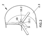
- the interior of the retractable-extendable section (2.2) of the hose (2) detail in Figure 2 ) is provided with a series of platens (10) with a central orifice (10.1) which provides a guide means for the cable (5), being the platens (10) attached to the interior wall (2.3) of the hose (2) by means of a series of preferably equidistant bands (9) which pass through slots (10.2) provided in the proximity of the periphery of the platens (9).
- the telescopic tube (1) comprises a tube (1.1) of a smaller cross section that has a tube (1.2) of a larger cross section sliding over its exterior onto which the retractable-extendable section (2.2) of the hose (2) is fastened using a cylindrical ring (1.2.1), preferably made of Teflon material, in combination with a bearing (1.2.2) fastened to the tube (1.2) of larger cross section, as well as a further cylindrical ring (1.2.1) fastened to end of the tube (1.2) of larger cross section, through which the hose (2) protrudes to attach an outlet elbow (11).
- a cylindrical ring (1.2.1 preferably made of Teflon material
- the telescopic tube (1) with the hose (2) disposed in its interior, is fastened to the lower part of the aircraft access bridge.
Landscapes
- Engineering & Computer Science (AREA)
- General Engineering & Computer Science (AREA)
- Mechanical Engineering (AREA)
- Aviation & Aerospace Engineering (AREA)
- Physics & Mathematics (AREA)
- Acoustics & Sound (AREA)
- Chemical & Material Sciences (AREA)
- Combustion & Propulsion (AREA)
- Supports For Pipes And Cables (AREA)
- Electric Cable Installation (AREA)
- Rigid Pipes And Flexible Pipes (AREA)
- Air-Flow Control Members (AREA)
- Duct Arrangements (AREA)
- Storing, Repeated Paying-Out, And Re-Storing Of Elongated Articles (AREA)
Claims (14)
- Luftgekühlte Vorrichtung zur Ausfahrung und Einfahrung eines Druckluftschlauchs für Luftfahrzeuge, welche ein Teleskoprohr (1) umfasst, in dessen Innerem ein Luftkühlungsschlauch (2) angeordnet ist, wobei diese über einen Motor (4) verfügt, der auf ein Kabel (5) einwirkt, das vorzugsweise aus Stahl gefertigt ist und in dem Inneren des Luftkühlungsschlauchs (2) angeordnet ist, und dadurch gekennzeichnet, dass diese weiterhin zwei Abschnitte umfasst:• einen Abschnitt (2.1) des Schlauchs (2), der eingefahren oder ausgefahren werden kann, welcher eine Reihe von elastischen, vorzugsweise kreisförmigen Elementen (6) mit einer zentralen Öffnung (6.1) einschließt, die ein Durchlassmittel für das Kabel (5) zur Verfügung stellt, wobei beide Seiten von jedem elastischen Element (6) mit Anschlägen (7) ausgestattet sind, die an dem Kabel (5) befestigt sind, so dass, wenn sich das besagte Kabel (5) bewegt, der entsprechende Anschlag (7) gegen das elastische Element (6) drückt, das dann in Kontakt mit einer Scheibe (8) tritt, die mit dem Schlauch (2) verbunden und auf jeder Seite des elastischen Elements (6) befindlich ist, was in der Einfahrung oder Ausfahrung des Abschnitts (2.1) des Schlauchs (2) resultiert, der eingefahren oder ausgefahren werden kann, bis das elastische Element (6) das Innere der Scheibe (8) passiert hat, und• einen Abschnitt (2.2) des Schlauchs (2), der nicht eingefahren oder ausgefahren werden kann, welcher eine Reihe von mit dem Schlauch (2) verbundenen Platten (10) mit einer zentralen Öffnung (10.1) einschließt, welche ein Führungsmittel für das Kabel (5) zur Verfügung stellt, wobei das Teleskoprohr (1) ein Rohr (1.1) mit kleinerem Druchmesser umfasst, welches ein Rohr (1.2) mit größerem Durchmesser besitzt, das über dessen Oberfläche gleitet, auf welcher der nicht einfahrbare/ausfahrbare Abschnitt (2.2) des Schlauchs (2) befestigt ist.
- Eine luftgekühlte Vorrichtung zur Ausfahrung und Einfahrung eines Druckluftschlauchs für Luftfahrzeuge nach Anspruch 1, dadurch gekennzeichnet, dass der Luftkühlungsschlauch (2) mittels eines Einlasskrümmers (3) mit dem Flughafenversorgungsnetz verbunden ist.
- Eine luftgekühlte Vorrichtung zur Ausfahrung und Einfahrung eines Druckluftschlauchs für Luftfahrzeuge nach Anspruch 1, dadurch gekennzeichnet, dass der Motor (4) während des Ausfahrvorgangs ausgekuppelt ist, so dass die Zugkraft seitens des Bedieners zur Verfügung gestellt wird, wenn dieser an dem Schlauch (2) zieht.
- Eine luftgekühlte Vorrichtung zur Ausfahrung und Einfahrung eines Druckluftschlauchs für Luftfahrzeuge nach Anspruch 1, dadurch gekennzeichnet, dass die Scheiben (8) mit einer Innenwand (2.3) des Schlauchs (2) mittels einer Reihe vorzugsweise äquidistanter Bänder (9) verbunden sind.
- Eine luftgekühlte Vorrichtung zur Ausfahrung und Einfahrung eines Druckluftschlauchs für Luftfahrzeuge nach Anspruch 1, dadurch gekennzeichnet, dass die Platten (10) mit einer Innenwand (2.3) des Schlauchs (2) mittels einer Reihe vorzugsweise äquidistanter Bänder (9) verbunden sind, die durch Schlitze (10.2) verlaufen, welche in der Nähe des Umfangs der Platten (9) zur Verfügung gestellt sind.
- Eine luftgekühlte Vorrichtung zur Ausfahrung und Einfahrung eines Druckluftschlauchs für Luftfahrzeuge nach Anspruch 1, dadurch gekennzeichnet, dass das Innere der Öffnung (6.1) des elastischen Elements mit einer Buchse (6.2) ausgestattet ist, um die Durchführung der Kabel (5) zu ermöglichen.
- Eine luftgekühlte Vorrichtung zur Ausfahrung und Einfahrung eines Druckluftschlauchs für Luftfahrzeuge nach Anspruch 1, dadurch gekennzeichnet, dass die Scheiben (8) eine ringförmige Form haben.
- Eine luftgekühlte Vorrichtung zur Ausfahrung und Einfahrung eines Druckluftschlauchs für Luftfahrzeuge nach Anspruch 1, dadurch gekennzeichnet, dass das Rohr (1.2) mit größerem Durchmesser mit einem zylinderförmigen Ring (1.2.1) ausgestattet ist, der vorzugsweise aus Teflonmaterial gefertigt ist, in Verbindung mit einem Wälzlager (1.2.2) an dem Ende, das mit dem Rohr (1.1) mit kleinerem Durchmesser verbunden ist, sowie mit einem weiteren zylinderförmigen Ring (1.2.1) an dem Ende, durch das der Schlauch (2) austritt, um einen Auslasskrümmer (11) zu befestigen.
- Eine luftgekühlte Vorrichtung zur Ausfahrung und Einfahrung eines Druckluftschlauchs für Luftfahrzeuge nach Anspruch 1, dadurch gekennzeichnet, dass ein kegelstumpfartiger Ring (1.1.1), der vorzugsweise aus Teflonmaterial gefertigt ist, an dem freien Ende des Rohrs (1.1) mit kleinerem Durchmesser vorgesehen ist, um die Fuge zwischen dem Rohr mit kleinerem Durchmesser (1.1) und dem Rohr mit größerem Durchmesser (1.2) abzudichten.
- Eine luftgekühlte Vorrichtung zur Ausfahrung und Einfahrung eines Druckluftschlauchs für Luftfahrzeuge nach Anspruch 1, dadurch gekennzeichnet, dass das Teleskoprohr (1) mit dem unteren Teil der Fluggastbrücke verbunden ist.
- Eine luftgekühlte Vorrichtung zur Ausfahrung und Einfahrung eines Druckluftschlauchs für Luftfahrzeuge nach Anspruch 1, dadurch gekennzeichnet, dass der Abschnitt (2.1) des Schlauchs (2), der eingefahren der ausgefahren werden kann, derjenige Abschnitt ist, der dem Motor (4) am nächsten liegt.
- Eine luftgekühlte Vorrichtung zur Ausfahrung und Einziehung eines Druckluftschlauchs für Luftfahrzeuge nach Anspruch 1, dadurch gekennzeichnet, dass die Platten (10) im Wesentlichen kreisförmig sind.
- Eine luftgekühlte Vorrichtung zur Ausfahrung und Einziehung eines Druckluftschlauchs für Luftfahrzeuge nach Anspruch 1, dadurch gekennzeichnet, dass der Auslass des Schlauchs (2) mit Sensoren ausgerüstet ist, die feststellen, ob der Schlauch (2) mit dem vorgekühlten Lufteinlass des Flugzeugs verbunden oder nicht verbunden ist, um die Aktivierung des Luftstroms von dem Flughafenversorgungsnetz zu erlauben oder zu verhindern.
- Eine luftgekühlte Vorrichtung zur Ausfahrung und Einziehung eines Druckluftschlauchs für Luftfahrzeuge nach Anspruch 1, dadurch gekennzeichnet, dass das Kabel (5) durch den Einlasskrümmer (3) des Motors (4) zu dem Schlauch (2) mittels einer Öffnung (3.1) verläuft, die mit einer Dichtung (3.2) abgedichtet ist.
Applications Claiming Priority (2)
| Application Number | Priority Date | Filing Date | Title |
|---|---|---|---|
| ES200501545A ES2289875B2 (es) | 2005-06-24 | 2005-06-24 | Dispositivo de extraccion y recogida de manguera de aire acondicionado para aviones. |
| PCT/ES2005/070118 WO2006136624A1 (es) | 2005-06-24 | 2005-08-03 | Dispositivo de extracción y recogida de manguera de aire acondicionado para aviones |
Publications (2)
| Publication Number | Publication Date |
|---|---|
| EP1894841A1 EP1894841A1 (de) | 2008-03-05 |
| EP1894841B1 true EP1894841B1 (de) | 2008-10-15 |
Family
ID=35976600
Family Applications (1)
| Application Number | Title | Priority Date | Filing Date |
|---|---|---|---|
| EP05782617A Expired - Lifetime EP1894841B1 (de) | 2005-06-24 | 2005-08-03 | Vorrichtung zum aus- und einfahren eines klimatisierten luftschlauches für ein flugzeug |
Country Status (5)
| Country | Link |
|---|---|
| EP (1) | EP1894841B1 (de) |
| AT (1) | ATE411221T1 (de) |
| DE (1) | DE602005010491D1 (de) |
| ES (2) | ES2289875B2 (de) |
| WO (1) | WO2006136624A1 (de) |
Families Citing this family (4)
| Publication number | Priority date | Publication date | Assignee | Title |
|---|---|---|---|---|
| ES2304216B1 (es) * | 2007-03-09 | 2009-07-24 | Bienvenido Peña Haro | Recogedor/extensor de mangueras de aire acondicionado. |
| ES2331983B1 (es) * | 2007-06-04 | 2010-10-25 | Bienvenido Peña Haro | Recogedor de mangueras de aire acondicionado. |
| US9365297B2 (en) | 2008-02-02 | 2016-06-14 | Twist, Inc. | Hose management system for supplying conditioned air to an aircraft |
| CN102706258A (zh) * | 2012-06-08 | 2012-10-03 | 济南黄河路桥工程公司 | 圆形检查井检测尺 |
Family Cites Families (6)
| Publication number | Priority date | Publication date | Assignee | Title |
|---|---|---|---|---|
| US3399545A (en) * | 1967-05-23 | 1968-09-03 | Lear Siegler Inc | Apparatus for connecting a stationary air conditioning unit to aircraft |
| US3521316A (en) * | 1968-11-05 | 1970-07-21 | Stanray Corp | Airplane loading ramp structure supplying utilities to the airplane |
| US4357860A (en) * | 1980-10-27 | 1982-11-09 | Mccormick-Morgan, Inc. | Telescoping conduit for pressurized air |
| US4543677A (en) * | 1984-04-09 | 1985-10-01 | Teledyne Industries, Inc. | Airtight telescoping rigid conduit |
| FR2742523B1 (fr) * | 1995-12-18 | 1998-02-27 | Pm X Sarl | Installation de gaines notamment de ventilation dans des locaux de grande hauteur |
| US6821201B2 (en) * | 2001-03-05 | 2004-11-23 | Boomair, L.L.C. | Device and a method for supplying conditioned air to an aircraft |
-
2005
- 2005-06-24 ES ES200501545A patent/ES2289875B2/es not_active Expired - Fee Related
- 2005-08-03 ES ES05782617T patent/ES2313408T3/es not_active Expired - Lifetime
- 2005-08-03 WO PCT/ES2005/070118 patent/WO2006136624A1/es not_active Ceased
- 2005-08-03 EP EP05782617A patent/EP1894841B1/de not_active Expired - Lifetime
- 2005-08-03 DE DE602005010491T patent/DE602005010491D1/de not_active Expired - Fee Related
- 2005-08-03 AT AT05782617T patent/ATE411221T1/de not_active IP Right Cessation
Also Published As
| Publication number | Publication date |
|---|---|
| ES2289875A1 (es) | 2008-02-01 |
| DE602005010491D1 (de) | 2008-11-27 |
| EP1894841A1 (de) | 2008-03-05 |
| ES2289875B2 (es) | 2009-09-11 |
| ES2313408T3 (es) | 2009-03-01 |
| WO2006136624A1 (es) | 2006-12-28 |
| ATE411221T1 (de) | 2008-10-15 |
Similar Documents
| Publication | Publication Date | Title |
|---|---|---|
| US6752175B1 (en) | Auxiliary device for repairing a pipeline | |
| EP1894841B1 (de) | Vorrichtung zum aus- und einfahren eines klimatisierten luftschlauches für ein flugzeug | |
| CA2075709A1 (en) | Apparatus for inspecting the interior of a lateral pipeline | |
| US11384885B2 (en) | Flexible double walled hose connection | |
| CN107543002B (zh) | 用于管道保护的系统和方法 | |
| US10619784B2 (en) | Apparatus for launching and receiving a pig into or from a pipeline | |
| EP0273960B1 (de) | Anordnung mit ventilfunktion | |
| EP2504238B1 (de) | Maschine zur verlängerung und einziehung eines wellrohrs | |
| US3364940A (en) | Fuel dispensing apparatus | |
| US4152936A (en) | Remotely controlled retractable insertion flowmeter | |
| US4852614A (en) | Shut-off device which can be inserted into a pipeline | |
| EP0535997B1 (de) | Schlauch mit Lecknachweis | |
| EP2874883B1 (de) | Vorrichtung zum ausfahren und einfahren eines flexiblen und dehnbaren schlauchs | |
| EP2173617B1 (de) | System zum transport und zur lagerung einer leitung zur luftzufuhr in einem flugzeug | |
| CA3058812C (en) | Device for providing conditioned air to an aircraft | |
| US5657508A (en) | Apparatus for the extraction of objects immobilized in a pneumatic transfer network | |
| CN210980980U (zh) | 一种利于安装空间优化的管箱清洁设备 | |
| US11118715B2 (en) | Segment isolation of internal pipe wall | |
| CN109515474B (zh) | 上水机器人及列车上水系统 | |
| CN121516809A (zh) | 一种撬装式乙醇装卸鹤管 | |
| CN222021466U (zh) | 一种基于机械胀套结构的空心车轴对接定心装置 | |
| JP2579213B2 (ja) | 航空機への送気装置 | |
| RU2826062C1 (ru) | Способ и система для перефутеровки трубопровода | |
| CN119878952B (zh) | 一种钢水罐热修车移动除尘管道用节能对接装置 | |
| CN112357591B (zh) | 一种瓶体收发装置 |
Legal Events
| Date | Code | Title | Description |
|---|---|---|---|
| PUAI | Public reference made under article 153(3) epc to a published international application that has entered the european phase |
Free format text: ORIGINAL CODE: 0009012 |
|
| 17P | Request for examination filed |
Effective date: 20070724 |
|
| AK | Designated contracting states |
Kind code of ref document: A1 Designated state(s): AT BE BG CH CY CZ DE DK EE ES FI FR GB GR HU IE IS IT LI LT LU LV MC NL PL PT RO SE SI SK TR |
|
| RIN1 | Information on inventor provided before grant (corrected) |
Inventor name: SANCHEZ RUBIO, FERNANDO Inventor name: SERI MORENO, LUIS MIGUEL Inventor name: PENA HARO, BIENVENIDO |
|
| GRAP | Despatch of communication of intention to grant a patent |
Free format text: ORIGINAL CODE: EPIDOSNIGR1 |
|
| RIN1 | Information on inventor provided before grant (corrected) |
Inventor name: SANCHEZ RUBIO, FERNANDO Inventor name: PENA HARO, BIENVENIDO Inventor name: SERI MORENO, LUIS MIGUEL |
|
| GRAS | Grant fee paid |
Free format text: ORIGINAL CODE: EPIDOSNIGR3 |
|
| GRAA | (expected) grant |
Free format text: ORIGINAL CODE: 0009210 |
|
| DAX | Request for extension of the european patent (deleted) | ||
| AK | Designated contracting states |
Kind code of ref document: B1 Designated state(s): AT BE BG CH CY CZ DE DK EE ES FI FR GB GR HU IE IS IT LI LT LU LV MC NL PL PT RO SE SI SK TR |
|
| REG | Reference to a national code |
Ref country code: CH Ref legal event code: EP Ref country code: GB Ref legal event code: FG4D |
|
| REG | Reference to a national code |
Ref country code: IE Ref legal event code: FG4D |
|
| REF | Corresponds to: |
Ref document number: 602005010491 Country of ref document: DE Date of ref document: 20081127 Kind code of ref document: P |
|
| REG | Reference to a national code |
Ref country code: ES Ref legal event code: FG2A Ref document number: 2313408 Country of ref document: ES Kind code of ref document: T3 |
|
| NLV1 | Nl: lapsed or annulled due to failure to fulfill the requirements of art. 29p and 29m of the patents act | ||
| PG25 | Lapsed in a contracting state [announced via postgrant information from national office to epo] |
Ref country code: AT Free format text: LAPSE BECAUSE OF FAILURE TO SUBMIT A TRANSLATION OF THE DESCRIPTION OR TO PAY THE FEE WITHIN THE PRESCRIBED TIME-LIMIT Effective date: 20081015 Ref country code: BG Free format text: LAPSE BECAUSE OF FAILURE TO SUBMIT A TRANSLATION OF THE DESCRIPTION OR TO PAY THE FEE WITHIN THE PRESCRIBED TIME-LIMIT Effective date: 20090115 Ref country code: LT Free format text: LAPSE BECAUSE OF FAILURE TO SUBMIT A TRANSLATION OF THE DESCRIPTION OR TO PAY THE FEE WITHIN THE PRESCRIBED TIME-LIMIT Effective date: 20081015 |
|
| PG25 | Lapsed in a contracting state [announced via postgrant information from national office to epo] |
Ref country code: IS Free format text: LAPSE BECAUSE OF FAILURE TO SUBMIT A TRANSLATION OF THE DESCRIPTION OR TO PAY THE FEE WITHIN THE PRESCRIBED TIME-LIMIT Effective date: 20090215 Ref country code: FI Free format text: LAPSE BECAUSE OF FAILURE TO SUBMIT A TRANSLATION OF THE DESCRIPTION OR TO PAY THE FEE WITHIN THE PRESCRIBED TIME-LIMIT Effective date: 20081015 Ref country code: LV Free format text: LAPSE BECAUSE OF FAILURE TO SUBMIT A TRANSLATION OF THE DESCRIPTION OR TO PAY THE FEE WITHIN THE PRESCRIBED TIME-LIMIT Effective date: 20081015 Ref country code: PT Free format text: LAPSE BECAUSE OF FAILURE TO SUBMIT A TRANSLATION OF THE DESCRIPTION OR TO PAY THE FEE WITHIN THE PRESCRIBED TIME-LIMIT Effective date: 20090316 Ref country code: NL Free format text: LAPSE BECAUSE OF FAILURE TO SUBMIT A TRANSLATION OF THE DESCRIPTION OR TO PAY THE FEE WITHIN THE PRESCRIBED TIME-LIMIT Effective date: 20081015 Ref country code: SI Free format text: LAPSE BECAUSE OF FAILURE TO SUBMIT A TRANSLATION OF THE DESCRIPTION OR TO PAY THE FEE WITHIN THE PRESCRIBED TIME-LIMIT Effective date: 20081015 Ref country code: PL Free format text: LAPSE BECAUSE OF FAILURE TO SUBMIT A TRANSLATION OF THE DESCRIPTION OR TO PAY THE FEE WITHIN THE PRESCRIBED TIME-LIMIT Effective date: 20081015 |
|
| PG25 | Lapsed in a contracting state [announced via postgrant information from national office to epo] |
Ref country code: BE Free format text: LAPSE BECAUSE OF FAILURE TO SUBMIT A TRANSLATION OF THE DESCRIPTION OR TO PAY THE FEE WITHIN THE PRESCRIBED TIME-LIMIT Effective date: 20081015 Ref country code: DK Free format text: LAPSE BECAUSE OF FAILURE TO SUBMIT A TRANSLATION OF THE DESCRIPTION OR TO PAY THE FEE WITHIN THE PRESCRIBED TIME-LIMIT Effective date: 20081015 Ref country code: EE Free format text: LAPSE BECAUSE OF FAILURE TO SUBMIT A TRANSLATION OF THE DESCRIPTION OR TO PAY THE FEE WITHIN THE PRESCRIBED TIME-LIMIT Effective date: 20081015 Ref country code: RO Free format text: LAPSE BECAUSE OF FAILURE TO SUBMIT A TRANSLATION OF THE DESCRIPTION OR TO PAY THE FEE WITHIN THE PRESCRIBED TIME-LIMIT Effective date: 20081015 |
|
| PLBE | No opposition filed within time limit |
Free format text: ORIGINAL CODE: 0009261 |
|
| STAA | Information on the status of an ep patent application or granted ep patent |
Free format text: STATUS: NO OPPOSITION FILED WITHIN TIME LIMIT |
|
| PG25 | Lapsed in a contracting state [announced via postgrant information from national office to epo] |
Ref country code: IT Free format text: LAPSE BECAUSE OF FAILURE TO SUBMIT A TRANSLATION OF THE DESCRIPTION OR TO PAY THE FEE WITHIN THE PRESCRIBED TIME-LIMIT Effective date: 20081015 Ref country code: CZ Free format text: LAPSE BECAUSE OF FAILURE TO SUBMIT A TRANSLATION OF THE DESCRIPTION OR TO PAY THE FEE WITHIN THE PRESCRIBED TIME-LIMIT Effective date: 20081015 Ref country code: SE Free format text: LAPSE BECAUSE OF FAILURE TO SUBMIT A TRANSLATION OF THE DESCRIPTION OR TO PAY THE FEE WITHIN THE PRESCRIBED TIME-LIMIT Effective date: 20090115 |
|
| 26N | No opposition filed |
Effective date: 20090716 |
|
| PG25 | Lapsed in a contracting state [announced via postgrant information from national office to epo] |
Ref country code: SK Free format text: LAPSE BECAUSE OF FAILURE TO SUBMIT A TRANSLATION OF THE DESCRIPTION OR TO PAY THE FEE WITHIN THE PRESCRIBED TIME-LIMIT Effective date: 20081015 |
|
| PG25 | Lapsed in a contracting state [announced via postgrant information from national office to epo] |
Ref country code: MC Free format text: LAPSE BECAUSE OF NON-PAYMENT OF DUE FEES Effective date: 20090831 |
|
| REG | Reference to a national code |
Ref country code: CH Ref legal event code: PL |
|
| GBPC | Gb: european patent ceased through non-payment of renewal fee |
Effective date: 20090803 |
|
| PG25 | Lapsed in a contracting state [announced via postgrant information from national office to epo] |
Ref country code: CH Free format text: LAPSE BECAUSE OF NON-PAYMENT OF DUE FEES Effective date: 20090831 Ref country code: LI Free format text: LAPSE BECAUSE OF NON-PAYMENT OF DUE FEES Effective date: 20090831 |
|
| REG | Reference to a national code |
Ref country code: IE Ref legal event code: MM4A |
|
| PG25 | Lapsed in a contracting state [announced via postgrant information from national office to epo] |
Ref country code: DE Free format text: LAPSE BECAUSE OF NON-PAYMENT OF DUE FEES Effective date: 20100302 Ref country code: IE Free format text: LAPSE BECAUSE OF NON-PAYMENT OF DUE FEES Effective date: 20090803 |
|
| PG25 | Lapsed in a contracting state [announced via postgrant information from national office to epo] |
Ref country code: GR Free format text: LAPSE BECAUSE OF FAILURE TO SUBMIT A TRANSLATION OF THE DESCRIPTION OR TO PAY THE FEE WITHIN THE PRESCRIBED TIME-LIMIT Effective date: 20090116 |
|
| PG25 | Lapsed in a contracting state [announced via postgrant information from national office to epo] |
Ref country code: GB Free format text: LAPSE BECAUSE OF NON-PAYMENT OF DUE FEES Effective date: 20090803 |
|
| PGFP | Annual fee paid to national office [announced via postgrant information from national office to epo] |
Ref country code: FR Payment date: 20100715 Year of fee payment: 6 |
|
| PG25 | Lapsed in a contracting state [announced via postgrant information from national office to epo] |
Ref country code: LU Free format text: LAPSE BECAUSE OF NON-PAYMENT OF DUE FEES Effective date: 20090803 |
|
| PG25 | Lapsed in a contracting state [announced via postgrant information from national office to epo] |
Ref country code: HU Free format text: LAPSE BECAUSE OF FAILURE TO SUBMIT A TRANSLATION OF THE DESCRIPTION OR TO PAY THE FEE WITHIN THE PRESCRIBED TIME-LIMIT Effective date: 20090416 |
|
| PG25 | Lapsed in a contracting state [announced via postgrant information from national office to epo] |
Ref country code: TR Free format text: LAPSE BECAUSE OF FAILURE TO SUBMIT A TRANSLATION OF THE DESCRIPTION OR TO PAY THE FEE WITHIN THE PRESCRIBED TIME-LIMIT Effective date: 20081015 |
|
| PG25 | Lapsed in a contracting state [announced via postgrant information from national office to epo] |
Ref country code: CY Free format text: LAPSE BECAUSE OF FAILURE TO SUBMIT A TRANSLATION OF THE DESCRIPTION OR TO PAY THE FEE WITHIN THE PRESCRIBED TIME-LIMIT Effective date: 20081015 |
|
| REG | Reference to a national code |
Ref country code: FR Ref legal event code: ST Effective date: 20120430 |
|
| PG25 | Lapsed in a contracting state [announced via postgrant information from national office to epo] |
Ref country code: FR Free format text: LAPSE BECAUSE OF NON-PAYMENT OF DUE FEES Effective date: 20110831 |
|
| PGFP | Annual fee paid to national office [announced via postgrant information from national office to epo] |
Ref country code: ES Payment date: 20120731 Year of fee payment: 7 |
|
| REG | Reference to a national code |
Ref country code: ES Ref legal event code: FD2A Effective date: 20131023 |
|
| PG25 | Lapsed in a contracting state [announced via postgrant information from national office to epo] |
Ref country code: ES Free format text: LAPSE BECAUSE OF NON-PAYMENT OF DUE FEES Effective date: 20120804 |