EP1892871A2 - Auf hoher Modulationsordnung basierendes Burst-Abbildungsverfahren und Vorrichtung in einem mobilen Kommunikationssystem - Google Patents
Auf hoher Modulationsordnung basierendes Burst-Abbildungsverfahren und Vorrichtung in einem mobilen Kommunikationssystem Download PDFInfo
- Publication number
- EP1892871A2 EP1892871A2 EP07016425A EP07016425A EP1892871A2 EP 1892871 A2 EP1892871 A2 EP 1892871A2 EP 07016425 A EP07016425 A EP 07016425A EP 07016425 A EP07016425 A EP 07016425A EP 1892871 A2 EP1892871 A2 EP 1892871A2
- Authority
- EP
- European Patent Office
- Prior art keywords
- bits
- bit
- positions
- burst
- user data
- Prior art date
- Legal status (The legal status is an assumption and is not a legal conclusion. Google has not performed a legal analysis and makes no representation as to the accuracy of the status listed.)
- Granted
Links
Images













Classifications
-
- H—ELECTRICITY
- H04—ELECTRIC COMMUNICATION TECHNIQUE
- H04J—MULTIPLEX COMMUNICATION
- H04J13/00—Code division multiplex systems
- H04J13/16—Code allocation
-
- H—ELECTRICITY
- H04—ELECTRIC COMMUNICATION TECHNIQUE
- H04L—TRANSMISSION OF DIGITAL INFORMATION, e.g. TELEGRAPHIC COMMUNICATION
- H04L1/00—Arrangements for detecting or preventing errors in the information received
- H04L1/004—Arrangements for detecting or preventing errors in the information received by using forward error control
- H04L1/0041—Arrangements at the transmitter end
-
- H—ELECTRICITY
- H04—ELECTRIC COMMUNICATION TECHNIQUE
- H04L—TRANSMISSION OF DIGITAL INFORMATION, e.g. TELEGRAPHIC COMMUNICATION
- H04L1/00—Arrangements for detecting or preventing errors in the information received
- H04L1/004—Arrangements for detecting or preventing errors in the information received by using forward error control
- H04L1/0056—Systems characterized by the type of code used
- H04L1/0071—Use of interleaving
-
- H—ELECTRICITY
- H04—ELECTRIC COMMUNICATION TECHNIQUE
- H04L—TRANSMISSION OF DIGITAL INFORMATION, e.g. TELEGRAPHIC COMMUNICATION
- H04L1/00—Arrangements for detecting or preventing errors in the information received
- H04L1/004—Arrangements for detecting or preventing errors in the information received by using forward error control
- H04L1/0072—Error control for data other than payload data, e.g. control data
-
- H—ELECTRICITY
- H04—ELECTRIC COMMUNICATION TECHNIQUE
- H04L—TRANSMISSION OF DIGITAL INFORMATION, e.g. TELEGRAPHIC COMMUNICATION
- H04L1/00—Arrangements for detecting or preventing errors in the information received
- H04L1/0078—Avoidance of errors by organising the transmitted data in a format specifically designed to deal with errors, e.g. location
- H04L1/0086—Unequal error protection
- H04L1/0088—Unequal error protection in control part
-
- H—ELECTRICITY
- H04—ELECTRIC COMMUNICATION TECHNIQUE
- H04L—TRANSMISSION OF DIGITAL INFORMATION, e.g. TELEGRAPHIC COMMUNICATION
- H04L27/00—Modulated-carrier systems
- H04L27/32—Carrier systems characterised by combinations of two or more of the types covered by groups H04L27/02, H04L27/10, H04L27/18 or H04L27/26
- H04L27/34—Amplitude- and phase-modulated carrier systems, e.g. quadrature-amplitude modulated carrier systems
- H04L27/3488—Multiresolution systems
-
- H—ELECTRICITY
- H04—ELECTRIC COMMUNICATION TECHNIQUE
- H04L—TRANSMISSION OF DIGITAL INFORMATION, e.g. TELEGRAPHIC COMMUNICATION
- H04L27/00—Modulated-carrier systems
- H04L27/32—Carrier systems characterised by combinations of two or more of the types covered by groups H04L27/02, H04L27/10, H04L27/18 or H04L27/26
- H04L27/34—Amplitude- and phase-modulated carrier systems, e.g. quadrature-amplitude modulated carrier systems
- H04L27/36—Modulator circuits; Transmitter circuits
Definitions
- the present invention relates generally to a burst mapping method and apparatus in a mobile communication system, and, in particular, to a method and apparatus for efficiently performing burst mapping using 16-ary Quadrature Amplitude Modulation (16-QAM) and symbol mapping in a Global System for Mobile communication (GSM)/Enhanced Data rates for GSM Evolution (EDGE) system.
- 16-QAM 16-ary Quadrature Amplitude Modulation
- GSM Global System for Mobile communication
- EDGE Enhanced Data rates for GSM Evolution
- GSM/EDGE which is a European communication system
- different coding schemes can be used according to the modulation scheme and the coding scheme.
- the modulation scheme used in the GSM/EDGE system can include Gaussian Minimum Shift Keying (GMSK) and 8-ary Phase Shift Keying (PSK) modulation schemes.
- GMSK Gaussian Minimum Shift Keying
- PSK Phase Shift Keying
- the GMSK scheme which is a scheme for limiting a bandwidth by passing binary data through a Gaussian low-pass filter and then performing frequency modulation with a predetermined deviation ratio, allows an interval between two frequencies to continuously change, thereby providing high spectrum concentration and high out-band spectrum suppression.
- the 8-PSK scheme which is a scheme for mapping data to a phase-shifted code of a sub-carrier for modulation, can increase frequency efficiency.
- PDTCH Packet Data Traffic Channels
- the thirteen techniques include four schemes of Coding Schemes (CSs), CS-1/2/3/4 for General Packet Radio Service (GPRS), and nine schemes of Modulation and Coding Schemes (MCSs), MCS-1 to MCS-9 for Enhanced General Packet Radio Service (EGPRS).
- CSs Coding Schemes
- GPRS General Packet Radio Service
- MCSs Modulation and Coding Schemes
- MCS-1 to MCS-9 for Enhanced General Packet Radio Service
- the modulation schemes and the coding techniques are selected and used.
- the combinations can be identified as MCSs.
- EDGE is an extension scheme for a GSM data service, and the EDGE system generally supports Enhanced Circuit-Switched Data (ECSD) and EGPRS.
- EGPRS uses nine schemes of MCS-1 to MCS-9, each combined of a modulation scheme and a coding scheme.
- MCS-1 to MCS-4 each use the GMSK modulation scheme, and MCS-5 to MCS-9 each use the 8-PSK modulation scheme.
- One of the nine MCSs can be determined according to input data.
- FIG. 1 illustrates a structure of a downlink transmitter using MCS-5 to MCS-9 in an EDGE system.
- a Radio Link Control (RLC) packet data block (RLC block) 110 separately outputs Uplink State Flag (USF), header and user data to an encoder 120 according to input user data.
- RLC packet data block RLC block 110 separately outputs Uplink State Flag (USF), header and user data to an encoder 120 according to input user data.
- RLC packet data block 110 separately outputs Uplink State Flag (USF), header and user data to an encoder 120 according to input user data.
- RLC packet data block 110 separately outputs Uplink State Flag (USF), header and user data to an encoder 120 according to input user data.
- UDF Uplink State Flag
- one RLC packet is composed of USF, header and source data.
- the encoder 120 can include a USF precoding block 121 for USF coding; a cyclic code adder 123 and a convolutional encoder 125 for header coding; and a cyclic code adder 127 and a convolutional encoder 129 for data coding.
- the USF, header and data received from the RLC block 110 are input to the USF precoding block 121, cyclic code adder 123 and cyclic code adder 127, respectively, and then coded therein.
- the USF undergoes precoding in the USF precoding block 121, and the header undergoes convolutional coding in the convolutional encoder 125 after a Cyclic Redundancy Check (CRC) code is added thereto in the cyclic code adder 123.
- CRC Cyclic Redundancy Check
- the header undergoes coding.
- the data undergoes coding through the cyclic code adder 127 and the convolutional encoder 129.
- An interleaver 130 for the header interleaves the coded header output from the convolutional encoder 125.
- An interleaver 140 for the data interleaves the coded data output from the convolutional encoder 129.
- a burst mapper 150 performs burst mapping on the coded bits of the USF, header and data output, respectively, from the USF precoding block 121 and the interleavers 130 and 140, to allocate the coded bits to four bursts in a distributed manner.
- the burst mapper 150 outputs the bits allocated to four bursts, to an 8-PSK modulator 160.
- the 8-PSK modulator 160 performs 8-PSK modulation on the bursts received from the burst mapper 150 before transmission.
- D/A Digital-to-Analog
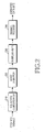
- FIG. 2 illustrates a structure of a downlink receiver using MCS-5 to MCS-9 in an EDGE system.
- an equalizer/demodulator 210 performs signal-to-noise equalization on the signal received from the transmitter of FIG. 1, performs demodulation thereon, and then outputs the resulting signal to a burst demapper 220.
- the burst demapper 220 demaps the input signal into the bits before they were mapped/allocated to four bursts in the transmitter, i.e. into signaling data such as user data (data source), USF, header, etc.
- the signaling data means control information.
- a deinterleaver 230 performs deinterleaving on the bits output from the burst demapper 220.
- a channel decoder 240 performs channel decoding on the bits output from the deinterleaver 230. In this manner, the original data is restored.
- the receiver can further include a Radio Frequency (RF) unit for receiving an analog signal over the air, and an Analog-to-Digital (A/D) converter for converting the analog signal into a digital signal
- RF Radio Frequency
- A/D Analog-to-Digital
- the existing MCS-5 to MCS-9 using the 8-PSK modulation scheme although they can increase frequency efficiency due to a characteristic of the 8-PSK scheme, are apt to suffer from noise because of a decrease in the distance between phase states.
- 3GPP 3rd Generation Partnership Project
- GERAN GSM/EDGE Radio Access Network
- 3GPP 3rd Generation Partnership Project
- GERAN GSM/EDGE Radio Access Network
- UMTS Universal Mobile Telecommunication Service
- the currently considered turbo code having a mother coding rate of 1/3, is the same turbo code as that in the existing UMTS system.
- one information bit frame can be divided into information bits and parity bits through coding.
- the turbo encoder separates the one information bit frame into information bits (or systematic bits) and parity bits. That is, the coded output is separated into an information bit stream and a parity bit stream after undergoing a puncturing and rate matching algorithm according to a channel coding rate.
- SMP Symbol Mapping based on Priority
- SMP interleaves information bits and parity bits independently, and then maps the interleaved information bits and parity bits to higher-reliability bit positions and lower-reliability bit positions according to priority of the bits, before transmission.
- important data is allocated to the higher-reliability bit positions in a modulation symbol, and less important data is allocated to the lower-reliability bit positions in the modulation symbol before being transmitted, thereby increasing reliability of the system.
- FIG. 3 illustrates a Gray-encoded signal constellation available in a 16-QAM modulation scheme of a UMTS system.
- four signal points are located in each area in a quadrant composed of an In-Phase (I) axis and a Quadrature-Phase (Q) axis. That is, S 1 , S 2 , S 3 , S 4 are located in an area one (A1) 310; S 5 , S 6 , S 7 , S 8 are located in an area two (A2) 320; S 9 , S 10 , S 11 , S 12 are located in an area three (A3) 330; and S 13 , S 14 S 15 , S 16 are located in an area four (A4) 340.
- I In-Phase
- Q Quadrature-Phase
- the signal points each correspond to modulation symbols each composed of 4 bits, and Gray coding is performed for allocation as shown in FIG. 3 so that signal points, first and third bits of which are the same bits, exist in the same area. Therefore, in the illustrated constellation, first and second bit positions in each modulation symbol are higher-reliability bit positions (H), whereas third and fourth bit positions are lower-reliability bit positions (L).
- An aspect of the present invention is to address at least the above problems and/or disadvantages and to provide at least the advantages described below. Accordingly, an aspect of the present invention is to provide a data transmission/reception method and apparatus for improving performance of a GSM/EDGE Evolution communication system.
- Another aspect of the present invention is to provide burst mapping method and apparatus for efficiently transmitting/receiving data in a GSM/EDGE Evolution communication system.
- Another aspect of the present invention is to provide a method and apparatus for allocating/transmitting data having reliability corresponding to reliability of 16-QAM symbol bits during burst mapping, thereby maximizing a turbo coding gain.
- the burst mapping method includes generating control information bits and user data bits by encoding input control information and user data; dividing the control information bits and user data bits into more than two bursts; and arranging a Training Sequence Code (TSC) in a center of each burst, placing the coded control information bits in positions adjacent to the TSC, and swapping the user data bits with bits mapped to higher-reliability positions among the control information bits.
- TSC Training Sequence Code
- the burst mapping apparatus includes an encoder for generating control information bits and user data bits by encoding input control information and user data; a burst mapper for dividing the control information bits and user data bits into more than two bursts; and a symbol mapper for arranging a Training Sequence Code (TSC) in a center of each burst, placing the coded control information bits in positions adjacent to the TSC, and swapping the user data bits with bits mapped to higher-reliability positions among the control information bits.
- TSC Training Sequence Code
- a method for receiving data in a mobile communication system using the 16-QAM modulation scheme includes performing channel estimation on a received signal; swapping control information with bits mapped to higher-reliability positions among user data bits of more than two bursts obtained by demodulating the channel-estimated signal according to a 16-QAM signal constellation, thereby rearranging symbols of each burst; and classifying the rearranged bits in each burst into bits before they are mapped and allocated to the bursts.
- an apparatus for receiving data in a mobile communication system using a the 16-QAM modulation scheme includes a demodulator for performing channel estimation on a received signal; a symbol demapper for swapping control information with bits mapped to higher-reliability positions among user data bits of more than two bursts obtained by demodulating the channel-estimated signal according to a 16-QAM signal constellation, thereby rearranging symbols of each burst; and a burst demapper for classifying the rearranged bits in each burst into bits before they are mapped and allocated to the bursts.
- FIG. 4 illustrates a structure of a transmitter for transmitting a packet according to a preferred embodiment of the present invention.
- MCSs including 16-QAM, for example, MCS-7, MCS-8 and MCS-9 schemes used in the GERAN Evolution system.
- MCS-7, MCS-8 and MCS-9 schemes used in the GERAN Evolution system.
- MCS-9 schemes used in the GERAN Evolution system.
- the packet transmission/reception will recognize from the following description that the present invention can be achieved in other mobile communication systems having the similar technical background and channel format with a slight modification.
- an RLC packet data block (RLC block) 410 like the RLC block 110 of FIG. 1, separates USF, header and user data from input user data (or N transport blocks), and outputs them to a USF precoding block 420, a cyclic code adder 422, and a data coding chain (or data encoder) 430, respectively.
- RLC data packet herein is composed user data, 3-bit USF and 37-bit header.
- the USF and the header are control information.
- the 3-bit USF input to the USF precoding block 420 becomes a 36-bit coded USF through precoding, and is output to a burst mapper 440.
- the 37-bit header input to the cyclic code adder 422 becomes a 45-bit header after a CRC, or a cyclic code, is added thereto, and then is input to a convolutional encoder 424.
- the convolutional encoder 424 performs convolutional coding on the input 45-bit header, and then outputs a 124-bit coded header to an interleaver 426.
- the interleaver 426 performs interleaving on the coded header from the convolutional encoder 424, and outputs the resulting header to the burst mapper 440.
- the USF precoding block 420, cyclic code adder 422, convolutional encoder 424 and interleaver 426 correspond to a control information encoder.
- the user data differs in number of bits according to MCS applied thereto.
- the number of bits of the user data is 900 bits, and the 900-bit data is input to a turbo encoder 432 after a CRC code is added thereto in a cyclic code adder 431 by an error detection algorithm.
- the turbo encoder 432 performs a code puncturing and rate matching process on the CRC-added bits using a turbo code, and outputs 1688-bit coded data.
- a serial-to-parallel (S/P) converter 433 performs a serial-to-parallel conversion process on the input 1688-bit coded data to separate the data into systematic bits (S) 470 and parity bits (P) 480, and outputs them to interleavers 434 and 435, respectively.
- the interleaver 434 performs interleaving on the input information bits, and the interleaver 435 performs interleaving on the input parity bits, to generate their bit streams, i.e. an S stream and a P stream, and then output the bit streams to a parallel-to-serial (P/S) converter 436.
- P/S parallel-to-serial
- the parallel-to-serial converter 436 performs a parallel-to-serial conversion process on the input bit streams, and then outputs a single 1688-bit stream to the burst mapper 440.
- the number of bits for each processed in the data coding chain 430 described in regard to FIG. 4 is the number of bits for MCS-7.
- MCS-8 or MCS-9 the number of bits to be output from the reference numerals (entities) 460, 470 and 480 are subject to change.
- Table 1 the number of bits output from the data coding chain 430 is different according to MCS type.
- Reference numeral 460 Reference numeral 470 Reference numeral 480 MCS-7 900 bits 924 bits 764 bits MCS-8 1092 bits 1116 bits 572 bits MCS-9 1188 bits 1212 bits 476 bits
- the data source can be divided into two same bit streams and then input to the data coding chain 430 in which a CRC is added to each of the bit streams and then input to two turbo encoders.
- the burst mapper 440 performs burst mapping on the 36-bit USF, the 124-bit header, and the 1688-bit coded bits output, respectively, from the USF precoding block 420, the interleaver 426 and the parallel-to-serial converter 436, to allocate them to 4 bursts.
- the burst mapper 440 outputs the 4 bursts, to each of which 464 bit bits are allocated, to a symbol mapper 450.
- the symbol mapper 450 rearranges the bits allocated to each of the bursts according to an arrangement pattern based on reliability of a modulation symbol in the corresponding 16-QAM scheme to be used. That is, for the user data, the systematic bits are preferentially arranged in higher-reliability positions, and the parity bits are preferentially arranged in lower-reliability positions. USF u and header h, constituting control information, are arranged in the higher-reliability positions and the lower-reliability positions in a distributed manner. In arranging the control information, the symbol mapper 450 allocates bits of the control information to the place which is as close as possible to a Training Sequence Code (TSC) arranged in the center of each burst.
- TSC Training Sequence Code
- control information means signaling data
- control information and the signaling data are used in the same meaning.
- the symbol mapper 450 After performing the symbol mapping on the bursts, the symbol mapper 450 outputs the symbol-mapped bursts to a 16-QAM modulator 460.
- the symbol mapping method is described below in detail for individual embodiments. Although the symbol mapper 450 is separately shown herein for convenience, it can be included in the burst mapper 440.
- the 16-QAM modulator 460 performs 16-QAM modulation based on a predetermined signal constellation on the 4-bit modulation symbols of the bursts input from the burst mapper 440.
- a further detailed description-of the present invention is provided for the parts necessary for those of skill in the art to implement the present invention. That is, a description of a device additionally necessary for transferring the modulated signal, for example, a D/A converter, will be omitted herein since it is understood by those of skill in the art.
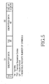
- FIG. 5 illustrates a structure of a normal burst according to a preferred embodiment of the present invention.
- the normal burst which is the most general burst structure used in the GSM/EDGE system, is transmitted within one time slot from a base station or a mobile station.
- the normal burst is roughly composed of a data part including user data and signaling data, and a TSC part.
- a TSC used for channel estimation is arranged in the TSC part, and the TSC is composed of 26 symbols.
- the data part includes coded user data and coded signaling data, and is divided into two 58-symbol parts D1 and D2, which are arranged to the left and right of the TSC, respectively, as shown in FIG. 5.
- the burst includes 3-symbol Tail Bit (TB) parts arranged to the left and right of the data parts D1 and D2, respectively, and an 8.25-symbol Guard Period (GP) located at the end of the burst, in addition to the data part and the TSC part.
- TB 3-symbol Tail Bit
- GP 8.25-symbol Guard Period
- the user data and signaling data of a total of 1856 bits input to the burst mapper 440 in FIG. 4 are allocated to 4 bursts on a distributed basis, so that 464 bits are allocated to 1 burst.
- 464 bits allocated to 1 burst include 422-bit data d, 31-bit header h, 9-bit USF u and 2-bit code identifier q, and are modulated with 116 16-QAM symbols before being transmitted.
- FIG. 6 a detailed description is provided of a structure of a 464-bit data part arranged in the 1 burst.
- FIG. 6 illustrates a structure of data arranged in 1 burst according to a preferred embodiment of the present invention.
- 1 symbol is composed of 4 bits
- 58-symbol data parts D1 and D2 each are composed of 232 bits in the 1 burst.
- D 1 is composed of 211-bit user data d, 15-bit header h and 6-bit USF u
- D2 is composed of 211-bit user data d, 16-bit header h, 3-bit USF u and 2-bit code identifier q.
- the 31-bit header h, 9-bit USF u and 2-bit code identifier q corresponding to the signaling data generally include important control information, they are preferentially allocated to the positions close to the TSC as shown in FIG. 5, and the user data is arranged in the remaining part.
- the 2-bit code identifier q is located in the place in contact with the TSC having good channel condition and high reliability.
- FIG. 7 illustrates a structure of data arranged in 1 burst according to another embodiment of the present invention.
- an alternative data arrangement although similar to the data arrangement shown in FIG. 6, provides that D1 includes 212-bit user data d, 15-bit header h and 5-bit USF u, and D2 includes 210-bit user data d, 16-bit header h, 4-bit USF u and 2-bit code identifier q.
- D1 includes 212-bit user data d
- 15-bit header h 15-bit header h and 5-bit USF u
- D2 includes 210-bit user data d, 16-bit header h, 4-bit USF u and 2-bit code identifier q.
- there are various other possible arrangement patterns there are various other possible arrangement patterns.
- FIG. 8 illustrates a 16-QAM symbol mapping rule to which SMP technology is applied, according to a preferred embodiment of the present invention.
- the above-described SMP technology allocates important data to higher-reliability bits and less important data to lower-reliability bits.
- the 16-QAM signal constellation shown in FIG. 3 because the signal points in the same area are equal in their first and second bits, the first and second bits have higher reliability, and the third and fourth bits have lower reliability.
- the first two bits (b n , b n+1 ) of the symbol are arranged in higher-reliability positions H, and the remaining two bits (b n+2 , b n+3 ) are arranged in lower-reliability positions L.
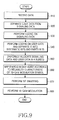
- FIG. 9 is a flowchart illustrating a symbol mapping process for a burst in a transmitter according to a preferred embodiment of the present invention.
- an RLC block 410 of FIG. 4 receives data.
- the RLC block 410 separates the input data into signaling data and user data.
- the signaling data includes 3-bit USF and 37-bit header.
- a coding process is performed on the signaling data. That is, in the signaling data, the 3-bit USF undergoes precoding in USF precoding block 420, and the 37-bit header becomes 45 bits after a CRC code is added thereto in cyclic code adder 422, and then becomes 124 bits after undergoing a convolutional coding process in convolutional encoder 424. Thereafter, the 124 bits are interleaved in interleaver 426.
- the precoding process on the USF and the precoding process on the header are performed in parallel.
- a coding process is performed on the user data.
- 900-bit data is input to cyclic code adder 431, and the cyclic code adder 431 adds a CRC code to the 900-bit data and outputs the resulting data to turbo encoder 432.
- the turbo encoder 432 performs code puncturing and rate matching on the input data, and outputs 1688-bit coded data to serial-to-parallel converter 433.
- the serial-to-parallel converter 433 divides the single data into 924 systematic bits and 764 parity bits, and transfers them to interleavers 434 and 435, respectively.
- the interleavers 434 and 435 perform interleaving on their input systematic bits and parity bits, respectively, and then transfer their output bits to parallel-to-serial converter 436.
- the parallel-to-serial converter 436 converts the divided systematic bits and parity bits into 1688-bit single data. In this manner, the coding on the user data is performed in step 940. Steps 930 and 940 are performed in parallel.
- burst mapper 440 uniformly arranges the 36-bit USF, 124-bit header and 1688-bit user data in 4 bursts such that each burst is composed of 464 bits.
- a symbol mapper 450 performs symbol mapping on the bits arranged in the bursts in step 950 according to reliability characteristic of modulation symbols based on the 16-QAM signal constellation, using one of the first to third embodiments described herein.
- an arrangement pattern of higher-reliability bit positions H and lower-reliability bit positions L are preferably HHLL or HLHL according to the 16-QAM modulation scheme used.
- systematic bits are preferentially allocated to the higher-reliability bit positions, and the parity bits are preferentially allocated to the lower-reliability bit positions.
- the control information bits are also allocated to the higher-reliability bit positions and the lower-reliability bit positions in a distributed manner, thereby providing the burst arrangement shown in FIGs. 6 or 7.
- step 970 the symbol mapper 450 selects control information bits to be swapped for the data mapped in step 960, and swaps the user data bits corresponding thereto. Depending on reliability of the control information bits to be swapped, the symbol mapper 450 swaps them with the user data bits having the reliability corresponding thereto. The bit swapping is performed to protect the signaling data.
- step 980 16-QAM modulator 460 performs 16-QAM modulation on four bits of the data bit-swapped in step 970.
- Burst mapping performed using the SMP symbol mapping technology follows the following rule.
- u and h bits arranged in H are swapped with the data arranged in H positions among the user data bits
- u and h bits arranged in L are swapped with the data arranged in L positions among the user data bits.
- Selection of the u and h bits to be swapped follows one of the following methods.
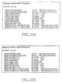
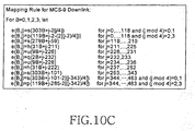
- FIGs. 10A, 10B and 10C illustrate burst mapping rules for MCS-7/8/9 downlinks, to which the first preferred embodiment of the present invention is applied.
- the illustrated burst mapping rules are for the cases where the data arrangement pattern for D1 and D2 parts of FIG. 6 is applied.
- FIG. 10A shows a mapping rule for MCS-7
- FIG. 10B shows a mapping rule for MCS-8
- FIG. 10C shows a mapping rule for MCS-9.
- B indicates a burst index
- j indicates a rearranged bit position (output bit position) in each burst
- s(i) indicates an i th systematic bit (also denoted as 'si')
- p(i) indicates an i th parity bit (also denoted as 'pi')
- h(i) indicates an i th header bit (also denoted as 'hi')
- u(i) indicates an i th USF bit (also denoted as 'ui')
- q(i) indicates a code identifier of an i th bit (also denoted as 'qi').
- a code identifier q0 is allocated to a bit #232 of D2
- q1 is allocated to a bit #233
- u6 is allocated to a bit #234
- u7 is allocated to a bit #235.
- the 'HHLL' symbol mapping rule shown in FIG. 8 is applied to every 4 bits beginning from a bit #0, or a start bit, of the burst.
- higher-reliability systematic bits s are preferentially allocated to the higher-reliability positions H
- lower-reliability parity bits p are preferentially allocated to lower-reliability positions L.
- some systematic bits may be allocated to the L positions.
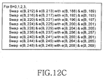
- FIG. 12A illustrates a swapping rule for swapping every second bit of signaling data according to the first embodiment of the present invention. By performing the bit swapping, signaling data including control information can be protected.
- FIG. 12B like FIG. 12A, illustrates a swapping rule for swapping every third bit of signaling data according to the first embodiment of the present invention.
- FIG. 12C is a diagram illustrating a swapping rule for swapping bit pairs of signaling data according to the first embodiment of the present invention.
- the signaling data bits can be swapped with the user data bits by means of other several swapping rules other than the foregoing swapping rules.
- Burst mapping performed using the SMP symbol mapping technology follows the following rule.
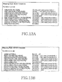
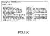
- FIGs. 13A, 13B and 13C illustrate burst mapping rules for MCS-7/8/9 downlinks to which the second embodiment of the present invention is applied.
- the illustrated burst mapping rules are for the cases where the data arrangement pattern for D1 and D2 parts of FIG. 6 is applied, and include even the burst mapping and bit swapping methods.
- FIG. 13A shows a mapping rule for MCS-7
- FIG. 13B shows a mapping rule for MCS-8
- FIG. 13C is a mapping rule for MCS-9.
- B indicates a burst index
- j indicates a bit position (output bit position) in a burst
- s indicates a systematic bit
- p indicates a parity bit
- h indicates a header bit
- u indicates USF
- q indicates a code identifier.
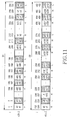
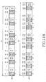
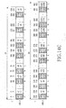
- FIGs. 14A, 14B and 14C illustrate structures of data arranged in a burst #0 using the mapping rules for MCS-7/8/9 of FIGs. 13A, 13B and 13C.
- FIGs. 14A, 14B and 14C illustrate structures of data D1 and D2 arranged according to the mapping rules of FIGs. 13A, 13B and 13C in the burst having the data structure shown in FIG. 6.
- a systematic bit s0 is allocated to a bit #0 of D1, s1 is allocated to a bit #1, a parity bit p0 is allocated to a bit #2, and p1 is allocated to a bit #3.
- a code identifier q0 is allocated to a bit #232 of D2
- q1 is allocated to a bit #233
- u6 is allocated to a bit #234
- u7 is allocated to a bit #235.
- the shaded parts mean higher-reliability positions H while the non-shaded parts mean lower-reliability positions L.
- the HHLL' symbol mapping rule shown in FIG. 8 is applied to every 4 bits beginning from a bit #0, or a start bit, of the burst. For example, bit positions #0 and #1 are positions of H, and bit positions #2 and #3 are positions of L, and bit positions #4 and #5 are positions of H. In this manner, higher-reliability systematic bits are preferentially allocated to the higher-reliability positions H, and lower-reliability parity bits are preferentially allocated to lower-reliability positions L. Shown in FIG.
- 14A is-the bit arrangement pattern after bit swapping has been completed according to the second embodiment, and it can be noted that the signaling data is allocated to the L positions.
- signaling data of h0, h1, h14, u0, u3, u4, u5, u6, u7 and u8 are arranged in the L positions, or the non-shaded part.
- FIG. 14A more systematic bits can be arranged in the H positions, compared to the first embodiment.
- FIGs. 14B and 14C also show arrangement patterns of data arranged for MCS-8 and MCS-9 in the same manner as that of FIG. 14A, respectively.
- Burst mapping performed using the SMP symbol mapping technology follows the following rule.
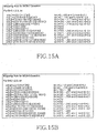
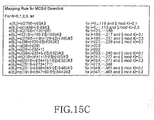
- FIGs. 15A, 15B and 15C illustrate burst mapping rules for MCS-7/8/9 downlinks to which the third preferred embodiment of the present invention is applied.
- the illustrated burst mapping rules are for the cases where the data arrangement pattern for D1 and D2 parts of FIG. 6 is applied, and include the burst mapping and bit swapping methods.
- FIG. 15A shows a mapping rule for MCS-7
- FIG. 15B shows a mapping rule for MCS-8
- FIG. 15C shows a mapping rule for MCS-9.
- B indicates a burst index
- j indicates a bit position (output bit position) in a burst
- s indicates a systematic bit
- p indicates a parity bit
- h indicates a header bit
- u indicates USF
- q indicates a code identifier.
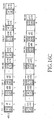
- FIGs. 16A, 16B and 16C illustrate structures of data arranged in a burst #0 using the mapping rules for MCS-7/8/9 of FIGs. 15A, 15B and 15C.
- FIGs. 16A, 16B and 16C illustrate structures of data D1 and D2 arranged according to the mapping rules of FIGs. 15A, 15B and 15C in the burst having the data structure shown in FIG. 6.
- a systematic bit s0 is allocated to a bit #0 of D1, s1 is allocated to a bit #1, a parity bit p0 is allocated to a bit #2, and p1 is allocated to a bit #3.
- a code identifier q1 is allocated to a bit #232 of D2, u5 is allocated to a bit #233, s115 is allocated to a bit #234, and s116 is allocated to a bit #235.
- the shaded parts mean higher-reliability positions H while the non-shaded parts mean lower-reliability positions L.
- the 'HHLL' symbol mapping rule shown in FIG. 8 is applied to every 4 bits beginning from a bit #0, or a start bit, of the burst. For example, bit positions #0 and #1 are positions of H, and bit positions #2 and #3 are positions of L, and bit positions #4 and #5 are positions of H. In this manner, higher-reliability systematic bits and signaling data are preferentially allocated to the higher-reliability positions H, and lower-reliability parity bits are preferentially allocated to lower-reliability positions L. Shown in FIG.
- 16A is the bit arrangement pattern after bit swapping has been completed according to the third embodiment, and it can be noted that the signaling data is allocated to the H positions. Therefore, in FIG. 16A, the important signaling data is arranged in the higher-reliability positions H before being transmitted.
- FIGs. 16B and 16C also show arrangement patterns of data arranged for MCS-8 and MCS-9 in the same manner as that of FIG. 16A, respectively.
- FIG. 17 illustrates a signal constellation Gray-encoded during 16-QAM modulation according to another embodiment of the present invention.
- the SMP scheme is applied with a HLHL pattern. Therefore, for the 4 consecutive data bits (b n , b n+1 , b n+2 , b n+3 ) constituting one 16-QAM symbol, first and third bits (b n , b n+2 ) are arranged in the H positions, and the remaining two bits (b n+1 , b n+3 ) are arranged in the L positions.
- the 16-QAM modulation scheme can arrange the signal constellation according to a circular 16-QAM scheme in addition to the above-mentioned rectangular 16-QAM scheme.
- This scheme is also called a 16-ary Amplitude Phase Keying (16-APK) modulation scheme.
- the circular 16-QAM can be classified into a circular (12,4) 16-QAM modulation scheme and a circular (8,8) 16-QAM modulation scheme according to arrangement of the signal constellation.
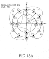
- FIGs. 18A and 18B illustrate signal constellations Gray-encoded during circular 16-QAM modulation according to another embodiment of the present invention.
- FIGs. 18A and 18B show two exemplary constellations for the circular (12,4) 16-QAM modulation scheme.
- signal points S 1 , S 2 , S 3 , S 4 in are A1 correspond to 0000, 0001, 0010, 0011, respectively, wherein first bits 0 and second bits 0 are all equal.
- Signal points S 5 , S 6 , S 7 , S 8 in area A2 correspond to 0100, 0101, 0110, 0111, respectively, wherein first bits 0 and second bits 1 are all equal.
- first bits and second bits are all equal in each area. That is, the signal points are allocated such that the first bits and the second bits should not be changed in the same area.
- the symbol mapping allocates higher-reliability bits to the unchanged first bits and second bits, and allocates lower-reliability bits to the third and fourth bits. That is, the SMP scheme is applied with the 'HHLL' pattern.
- signal points S 1 , S 2 , S 5 , S 6 in an area A1 correspond to 0000, 0001, 0100, 0101, respectively, wherein first bits 0 and third bits 0 are all equal.
- Signal points S 3 , S 4 , S 7 , S 8 in an A2 area correspond to 0010, 0011, 0110, 0111, respectively, wherein first bits 0 and third bits 1 are all equal.
- first bits and third bits are all equal in each area. That is, the signal points are allocated such that the first bits and the third bits should not be changed in the same area.
- the symbol mapping allocates higher-reliability bits to the unchanged first bits and third bits, and allocates lower-reliability bits to the second and fourth bits. That is, the SMP scheme is applied with the 'HLHL' pattern.
- Gray coding scheme of allocating bits to symbols in the constellation can apply the scheme of allocating first and second bits such that they should not be changed in the same area, and the scheme of allocating first and third bits such that they should not be changed in the same area.
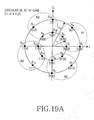
- FIGs. 19A and 19B illustrate signal constellations Gray-encoded during circular 16-QAM modulation according to yet another embodiment of the present invention.
- FIGs. 19A and 19B illustrate two exemplary constellations for the circular (8,8) 16-QAM modulation scheme.
- FIGs. 19A and 19B show that first bits and second bits for the signal points in the same area are all equal, and first bits and third bits for the signal points in the same area are all equal. That is, FIGs. 19A and 19B show two kinds of encoding schemes for circular (8,8) 16-QAM, and the symbol mapping according to a preferred embodiment of the present invention can be applied regardless of the radius ratio, as described above.
- FIG. 20 illustrates a structure of a receiver for receiving a packet according to a preferred embodiment of the present invention.
- the following description describes operation of performing the above-mentioned 16-QAM demodulation based on MCS-7/8/9.
- an equalizer/demodulator 2010 performs channel estimation and channel compensation on a signal received from the transmitter of FIG. 4, demodulates the channel-compensated signal according to the 16-QAM signal constellation used in the transmitter to separate the signal into 4 bursts, and outputs the bursts to a symbol demapper 2015.
- the symbol demapper 2015 rearranges bits in the bursts according to one mapping rule used by the transmitter among the above-mentioned symbol mapping rules, and then delivers the rearranged bits to a burst demapper 2020.
- the burst demapper 2020 classifies (demaps) the rearranged bits in each burst into the bits before mapping and allocating to 4 bursts in the transmitter, i.e. signaling data such as USF and header, and user data.
- the signaling data means control information, and bits corresponding to the signaling data are delivered to a controller (not shown) for performing corresponding processing. Bits corresponding to the user data are delivered to a deinterleaver block 2030.
- the deinterleaver block 2030 performs deinterleaving on the bits output from the burst demapper 2020.
- the deinterleaver block 2030 can include a serial-to-parallel (S/P) converter 2032, deinterleavers 2034 and 2036, and a parallel-to-serial converter 2038.
- the serial-to-parallel converter 2032 separates the input data bits into systematic bits and parity bits, and outputs to associated deinterleavers 2034 and 2036.
- the deinterleavers 2034 and 2036 perform deinterleaving on input systematic bits and parity bits, respectively, and output the resulting bits to the parallel-to-serial converter 2038.
- the parallel-to-serial converter 2038 performs a parallel-to-serial conversion process on the deinterleaved systematic bits and parity bits, and then outputs the resulting bits to a turbo decoder 2040.
- the turbo decoder 2040 performs turbo decoding on the input systematic and parity bits, thereby acquiring user data estimated from the received signal.
- the description has been made of an operation in which the deinterleaver block 2030 and the turbo decoder 2040 perform a decoding process on the user data.
- the deinterleaver block 2030 and the turbo decoder 2040 can perform a decoding process even on the control information, i.e. USF and header, thereby acquiring control information estimated from the received signal.
- the decoding on the control information can be performed with corresponding decoders for the control information.
- reference will be made to the decoded control information, for operations of the deinterleaver block 2030 and the turbo decoder 2040.
- burst mapping methods are for the GSM/EDGE downlink
- the proposed methods can be extended and applied even to the GSM/EDGE uplink in the same way.
- the main difference between GSM/EDGE downlink and GSM/EDGE uplink is in that the USF bits used in the downlink are not used in the uplink system. Instead, in the uplink, the number of header bits increases by the number of USF bits used in the downlink. Therefore, with the total number of bits used for burst mapping unchanged, the burst mapping methods for the downlink can be applied.
- the present invention allows for design of efficient burst mapping for the GSM/EDGE system by applying the SMP technology to several types of 16-QAM modulation technologies, thereby improving the system performance without affecting the system complexity.
- the introduction of the turbo code and the 16-QAM modulation scheme contributes to an increase in spectrum efficiency, data rate, and reliability.
Landscapes
- Engineering & Computer Science (AREA)
- Computer Networks & Wireless Communication (AREA)
- Signal Processing (AREA)
- Digital Transmission Methods That Use Modulated Carrier Waves (AREA)
- Mobile Radio Communication Systems (AREA)
- Error Detection And Correction (AREA)
Applications Claiming Priority (1)
| Application Number | Priority Date | Filing Date | Title |
|---|---|---|---|
| KR1020060079245A KR100987269B1 (ko) | 2006-08-22 | 2006-08-22 | 이동통신 시스템에서 고차 변조 기반의 버스트 매핑 방법및 장치 |
Publications (3)
| Publication Number | Publication Date |
|---|---|
| EP1892871A2 true EP1892871A2 (de) | 2008-02-27 |
| EP1892871A3 EP1892871A3 (de) | 2013-05-08 |
| EP1892871B1 EP1892871B1 (de) | 2015-01-14 |
Family
ID=38826425
Family Applications (1)
| Application Number | Title | Priority Date | Filing Date |
|---|---|---|---|
| EP07016425.6A Not-in-force EP1892871B1 (de) | 2006-08-22 | 2007-08-22 | Auf hoher Modulationsordnung basierendes Burst-Abbildungsverfahren und Vorrichtung in einem mobilen Kommunikationssystem |
Country Status (4)
| Country | Link |
|---|---|
| US (1) | US8135082B2 (de) |
| EP (1) | EP1892871B1 (de) |
| KR (1) | KR100987269B1 (de) |
| WO (1) | WO2008023935A1 (de) |
Cited By (1)
| Publication number | Priority date | Publication date | Assignee | Title |
|---|---|---|---|---|
| WO2018077771A3 (de) * | 2016-10-24 | 2018-06-28 | Fraunhofer-Gesellschaft zur Förderung der angewandten Forschung e.V. | Interleaving für die übertragung von telegrammen mit variabler subpaketanzahl und sukzessiver decodierung |
Families Citing this family (22)
| Publication number | Priority date | Publication date | Assignee | Title |
|---|---|---|---|---|
| KR101329950B1 (ko) * | 2007-02-07 | 2013-11-14 | 삼성전자주식회사 | 이동통신 시스템에서 향상된 심볼 전송률을 적용한 데이터송수신 방법 및 장치 |
| KR20100077019A (ko) * | 2007-10-01 | 2010-07-06 | 인터디지탈 패튼 홀딩스, 인크 | Redhot a 및 b 무선 송수신 장치용 업링크 상태 플래그(usf) 복원 복잡도를 단순화하는 방법 |
| KR101334371B1 (ko) * | 2008-08-28 | 2013-11-29 | 한국전자통신연구원 | 심볼 매핑 방법 및 장치 |
| US8774315B2 (en) * | 2009-08-25 | 2014-07-08 | The Aerospace Corporation | Phase-optimized constant envelope transmission (POCET) method, apparatus and system |
| US8370706B2 (en) * | 2009-10-02 | 2013-02-05 | Infinera Corporation | Interleaved correction code transmission |
| CN102783112B (zh) * | 2009-12-21 | 2015-08-05 | 瑞典爱立信有限公司 | 数据调制 |
| CN102255703B (zh) * | 2010-05-19 | 2014-07-16 | 华为技术有限公司 | 一种预编码信息的发送和接收方法及装置 |
| FR2961613B1 (fr) * | 2010-06-18 | 2012-07-27 | Commissariat Energie Atomique | Procede de protection memoire configurable contre les erreurs permanentes et transitoires et dispositif apparente |
| CN105284088B (zh) * | 2014-04-17 | 2018-12-25 | 华为技术有限公司 | 一种编码调制和解调方法、装置及系统 |
| JP6502764B2 (ja) * | 2015-02-10 | 2019-04-17 | 日本放送協会 | 送信装置、受信装置、及び半導体チップ |
| EP3223446A1 (de) * | 2016-03-22 | 2017-09-27 | Xieon Networks S.à r.l. | Verfahren zum schutz einer verbindung in einem optischen netzwerk |
| TWI627846B (zh) * | 2016-03-30 | 2018-06-21 | 晨星半導體股份有限公司 | 等化增強模組、解調變系統以及等化增強方法 |
| US10201026B1 (en) | 2016-06-30 | 2019-02-05 | Acacia Communications, Inc. | Forward error correction systems and methods |
| US11296823B2 (en) * | 2017-05-30 | 2022-04-05 | Qualcomm Incorporated | Priority based mapping of encoded bits to symbols |
| US10069519B1 (en) * | 2018-01-23 | 2018-09-04 | Mitsubishi Electric Research Laboratories, Inc. | Partition based distribution matcher for probabilistic constellation shaping |
| WO2019148139A1 (en) * | 2018-01-26 | 2019-08-01 | California Institute Of Technology | Systems and methods for communicating by modulating data on zeros |
| KR102457566B1 (ko) * | 2018-02-22 | 2022-10-21 | 한국전자통신연구원 | 데이터 패킷의 버스트의 길이에 기초하여 변복조를 수행하는 변복조기 및 상기 복조기가 수행하는 방법 |
| US10505676B1 (en) | 2018-08-10 | 2019-12-10 | Acacia Communications, Inc. | System, method, and apparatus for interleaving data |
| SG11202108549YA (en) * | 2019-02-07 | 2021-09-29 | California Inst Of Techn | Systems and methods for communicating by modulating data on zeros in the presence of channel impairments |
| CN113055067B (zh) * | 2019-12-27 | 2024-04-26 | 中兴通讯股份有限公司 | 下行信号处理方法、装置及基站 |
| US11658682B2 (en) * | 2020-04-28 | 2023-05-23 | POSTECH Research and Business Development Foundation | Methods for encoding and decoding sparse code and orthogonal sparse superposition code |
| US11799700B1 (en) * | 2022-08-31 | 2023-10-24 | Qualcomm Incorporated | Decoding multi-level coded (MLC) systems |
Family Cites Families (13)
| Publication number | Priority date | Publication date | Assignee | Title |
|---|---|---|---|---|
| BR9611138A (pt) * | 1995-10-24 | 1999-12-28 | Gen Instrument Corp | Transmissão de sequência de sinais com comprimento variável através da camada fìsica de um formato de transmissão com múltiplas camadas |
| US6185259B1 (en) * | 1996-06-12 | 2001-02-06 | Ericsson Inc. | Transmitter/receiver for GMSK and offset-QAM |
| US6259744B1 (en) * | 1999-06-01 | 2001-07-10 | Motorola, Inc. | Method and apparatus for mapping bits to an information burst |
| US6430214B1 (en) * | 2000-05-22 | 2002-08-06 | Motorola, Inc. | Fading resistant multi-level QAM receiver |
| KR100539862B1 (ko) | 2001-04-04 | 2005-12-28 | 삼성전자주식회사 | 부호분할다중접속 이동통신시스템에서 데이타 송/수신장치및 방법 |
| US6738948B2 (en) * | 2001-04-09 | 2004-05-18 | Motorola, Inc. | Iteration terminating using quality index criteria of turbo codes |
| JP2004522360A (ja) * | 2001-06-09 | 2004-07-22 | サムスン エレクトロニクス カンパニー リミテッド | 通信システムの符号語シーケンスの再配列方法及び装置 |
| CN1221113C (zh) * | 2001-08-24 | 2005-09-28 | 连宇通信有限公司 | 基于增信删余卷积码与qam调制格码相结合的信道译码方法和系统 |
| KR100744347B1 (ko) * | 2001-10-29 | 2007-07-30 | 삼성전자주식회사 | 부호분할다중접속 이동통신시스템에서 데이터 송/수신장치 및 방법 |
| US6996189B1 (en) * | 2002-07-26 | 2006-02-07 | Jabil Circuit, Inc. | Symmetric spherical QAM constellation |
| KR100630143B1 (ko) * | 2002-09-30 | 2006-09-29 | 삼성전자주식회사 | 통신 시스템에서 셔플링 데이터의 수신 방법 및 장치 |
| US6919829B2 (en) * | 2003-06-20 | 2005-07-19 | Nokia Corporation | Bit swapping for different interleaving depths |
| FI20045318A0 (fi) | 2004-09-01 | 2004-09-01 | Nokia Corp | Kommunikointijärjestelmä, vastaanotin, ja menetelmä arvioida vastaanotetun signaalin laatua |
-
2006
- 2006-08-22 KR KR1020060079245A patent/KR100987269B1/ko not_active Expired - Fee Related
-
2007
- 2007-08-22 US US11/843,100 patent/US8135082B2/en active Active
- 2007-08-22 EP EP07016425.6A patent/EP1892871B1/de not_active Not-in-force
- 2007-08-22 WO PCT/KR2007/004019 patent/WO2008023935A1/en not_active Ceased
Cited By (2)
| Publication number | Priority date | Publication date | Assignee | Title |
|---|---|---|---|---|
| WO2018077771A3 (de) * | 2016-10-24 | 2018-06-28 | Fraunhofer-Gesellschaft zur Förderung der angewandten Forschung e.V. | Interleaving für die übertragung von telegrammen mit variabler subpaketanzahl und sukzessiver decodierung |
| US11483028B2 (en) | 2016-10-24 | 2022-10-25 | Fraunhofer-Gesellschaft zur Förderung der angewandten Forschung e.V. | Interleaving for the transfer of telegrams with a variable number of sub-packets and successive decoding |
Also Published As
| Publication number | Publication date |
|---|---|
| EP1892871B1 (de) | 2015-01-14 |
| KR20080017713A (ko) | 2008-02-27 |
| WO2008023935A1 (en) | 2008-02-28 |
| US20080049859A1 (en) | 2008-02-28 |
| KR100987269B1 (ko) | 2010-10-12 |
| EP1892871A3 (de) | 2013-05-08 |
| US8135082B2 (en) | 2012-03-13 |
Similar Documents
| Publication | Publication Date | Title |
|---|---|---|
| EP1892871B1 (de) | Auf hoher Modulationsordnung basierendes Burst-Abbildungsverfahren und Vorrichtung in einem mobilen Kommunikationssystem | |
| CA2271768C (en) | Coded modulation for fading channels | |
| CN1650527B (zh) | 使用互补模式映射的卷积码的数字音频广播方法和设备 | |
| US8699316B2 (en) | USF coding | |
| EP1101314B1 (de) | Verfahren und vorrichtung zur abbildung von bits auf ein informationsbündel | |
| EP1987678A1 (de) | Verfahren und system zur anwendung eines ungleichen fehlerschutzes auf unkomprimiertes video zur übertragung über drahtlose kanäle | |
| US7933352B2 (en) | Cross QAM modulation-based symbol mapping method and apparatus in a mobile communication system | |
| US20080313526A1 (en) | Apparatus and method for transmitting and receiving data in a mobile communication system | |
| JP2004526336A5 (de) | ||
| US8199850B2 (en) | Transmitter for communication systems employing an enhanced modulation scheme | |
| KR100686704B1 (ko) | 상이한 인터리빙 깊이들을 위한 비트 교환 | |
| KR101397801B1 (ko) | 이동통신 시스템에서 교차형 성상도를 갖는 qam 변조기반의 심볼 매핑 방법 및 장치 | |
| WO2008153330A1 (en) | Method and apparatus for transmitting/receiving data in mobile communication system | |
| KR101329950B1 (ko) | 이동통신 시스템에서 향상된 심볼 전송률을 적용한 데이터송수신 방법 및 장치 | |
| WO1999031809A1 (en) | Pragmatic trellis-coded modulation system and method therefor |
Legal Events
| Date | Code | Title | Description |
|---|---|---|---|
| PUAI | Public reference made under article 153(3) epc to a published international application that has entered the european phase |
Free format text: ORIGINAL CODE: 0009012 |
|
| 17P | Request for examination filed |
Effective date: 20070822 |
|
| AK | Designated contracting states |
Kind code of ref document: A2 Designated state(s): AT BE BG CH CY CZ DE DK EE ES FI FR GB GR HU IE IS IT LI LT LU LV MC MT NL PL PT RO SE SI SK TR |
|
| AX | Request for extension of the european patent |
Extension state: AL BA HR MK YU |
|
| RAP1 | Party data changed (applicant data changed or rights of an application transferred) |
Owner name: SAMSUNG ELECTRONICS CO., LTD. |
|
| PUAL | Search report despatched |
Free format text: ORIGINAL CODE: 0009013 |
|
| AK | Designated contracting states |
Kind code of ref document: A3 Designated state(s): AT BE BG CH CY CZ DE DK EE ES FI FR GB GR HU IE IS IT LI LT LU LV MC MT NL PL PT RO SE SI SK TR |
|
| AX | Request for extension of the european patent |
Extension state: AL BA HR MK RS |
|
| RIC1 | Information provided on ipc code assigned before grant |
Ipc: H04L 1/00 20060101AFI20130402BHEP Ipc: H04L 27/34 20060101ALI20130402BHEP |
|
| RBV | Designated contracting states (corrected) |
Designated state(s): AT BE BG CH CY CZ DE DK EE ES FI FR GB GR HU IE IS IT LI LT LU LV MC MT NL PL PT RO SE SI SK TR |
|
| AKX | Designation fees paid |
Designated state(s): AT BE BG CH CY CZ DE DK EE ES FI FR GB GR HU IE IS IT LI LT LU LV MC MT NL PL PT RO SE SI SK TR |
|
| GRAP | Despatch of communication of intention to grant a patent |
Free format text: ORIGINAL CODE: EPIDOSNIGR1 |
|
| INTG | Intention to grant announced |
Effective date: 20140828 |
|
| GRAS | Grant fee paid |
Free format text: ORIGINAL CODE: EPIDOSNIGR3 |
|
| GRAA | (expected) grant |
Free format text: ORIGINAL CODE: 0009210 |
|
| AK | Designated contracting states |
Kind code of ref document: B1 Designated state(s): AT BE BG CH CY CZ DE DK EE ES FI FR GB GR HU IE IS IT LI LT LU LV MC MT NL PL PT RO SE SI SK TR |
|
| REG | Reference to a national code |
Ref country code: GB Ref legal event code: FG4D |
|
| REG | Reference to a national code |
Ref country code: CH Ref legal event code: EP |
|
| REG | Reference to a national code |
Ref country code: IE Ref legal event code: FG4D |
|
| REG | Reference to a national code |
Ref country code: AT Ref legal event code: REF Ref document number: 707504 Country of ref document: AT Kind code of ref document: T Effective date: 20150215 |
|
| REG | Reference to a national code |
Ref country code: DE Ref legal event code: R096 Ref document number: 602007040041 Country of ref document: DE Effective date: 20150305 |
|
| REG | Reference to a national code |
Ref country code: DE Ref legal event code: R082 Ref document number: 602007040041 Country of ref document: DE |
|
| REG | Reference to a national code |
Ref country code: AT Ref legal event code: MK05 Ref document number: 707504 Country of ref document: AT Kind code of ref document: T Effective date: 20150114 |
|
| REG | Reference to a national code |
Ref country code: LT Ref legal event code: MG4D |
|
| PG25 | Lapsed in a contracting state [announced via postgrant information from national office to epo] |
Ref country code: FI Free format text: LAPSE BECAUSE OF FAILURE TO SUBMIT A TRANSLATION OF THE DESCRIPTION OR TO PAY THE FEE WITHIN THE PRESCRIBED TIME-LIMIT Effective date: 20150114 Ref country code: SE Free format text: LAPSE BECAUSE OF FAILURE TO SUBMIT A TRANSLATION OF THE DESCRIPTION OR TO PAY THE FEE WITHIN THE PRESCRIBED TIME-LIMIT Effective date: 20150114 Ref country code: ES Free format text: LAPSE BECAUSE OF FAILURE TO SUBMIT A TRANSLATION OF THE DESCRIPTION OR TO PAY THE FEE WITHIN THE PRESCRIBED TIME-LIMIT Effective date: 20150114 Ref country code: LT Free format text: LAPSE BECAUSE OF FAILURE TO SUBMIT A TRANSLATION OF THE DESCRIPTION OR TO PAY THE FEE WITHIN THE PRESCRIBED TIME-LIMIT Effective date: 20150114 Ref country code: BG Free format text: LAPSE BECAUSE OF FAILURE TO SUBMIT A TRANSLATION OF THE DESCRIPTION OR TO PAY THE FEE WITHIN THE PRESCRIBED TIME-LIMIT Effective date: 20150414 |
|
| PG25 | Lapsed in a contracting state [announced via postgrant information from national office to epo] |
Ref country code: PL Free format text: LAPSE BECAUSE OF FAILURE TO SUBMIT A TRANSLATION OF THE DESCRIPTION OR TO PAY THE FEE WITHIN THE PRESCRIBED TIME-LIMIT Effective date: 20150114 Ref country code: AT Free format text: LAPSE BECAUSE OF FAILURE TO SUBMIT A TRANSLATION OF THE DESCRIPTION OR TO PAY THE FEE WITHIN THE PRESCRIBED TIME-LIMIT Effective date: 20150114 Ref country code: IS Free format text: LAPSE BECAUSE OF FAILURE TO SUBMIT A TRANSLATION OF THE DESCRIPTION OR TO PAY THE FEE WITHIN THE PRESCRIBED TIME-LIMIT Effective date: 20150514 Ref country code: GR Free format text: LAPSE BECAUSE OF FAILURE TO SUBMIT A TRANSLATION OF THE DESCRIPTION OR TO PAY THE FEE WITHIN THE PRESCRIBED TIME-LIMIT Effective date: 20150415 Ref country code: LV Free format text: LAPSE BECAUSE OF FAILURE TO SUBMIT A TRANSLATION OF THE DESCRIPTION OR TO PAY THE FEE WITHIN THE PRESCRIBED TIME-LIMIT Effective date: 20150114 |
|
| REG | Reference to a national code |
Ref country code: DE Ref legal event code: R097 Ref document number: 602007040041 Country of ref document: DE |
|
| PG25 | Lapsed in a contracting state [announced via postgrant information from national office to epo] |
Ref country code: DK Free format text: LAPSE BECAUSE OF FAILURE TO SUBMIT A TRANSLATION OF THE DESCRIPTION OR TO PAY THE FEE WITHIN THE PRESCRIBED TIME-LIMIT Effective date: 20150114 Ref country code: RO Free format text: LAPSE BECAUSE OF FAILURE TO SUBMIT A TRANSLATION OF THE DESCRIPTION OR TO PAY THE FEE WITHIN THE PRESCRIBED TIME-LIMIT Effective date: 20150114 Ref country code: CZ Free format text: LAPSE BECAUSE OF FAILURE TO SUBMIT A TRANSLATION OF THE DESCRIPTION OR TO PAY THE FEE WITHIN THE PRESCRIBED TIME-LIMIT Effective date: 20150114 Ref country code: EE Free format text: LAPSE BECAUSE OF FAILURE TO SUBMIT A TRANSLATION OF THE DESCRIPTION OR TO PAY THE FEE WITHIN THE PRESCRIBED TIME-LIMIT Effective date: 20150114 Ref country code: SK Free format text: LAPSE BECAUSE OF FAILURE TO SUBMIT A TRANSLATION OF THE DESCRIPTION OR TO PAY THE FEE WITHIN THE PRESCRIBED TIME-LIMIT Effective date: 20150114 |
|
| PLBE | No opposition filed within time limit |
Free format text: ORIGINAL CODE: 0009261 |
|
| STAA | Information on the status of an ep patent application or granted ep patent |
Free format text: STATUS: NO OPPOSITION FILED WITHIN TIME LIMIT |
|
| 26N | No opposition filed |
Effective date: 20151015 |
|
| PG25 | Lapsed in a contracting state [announced via postgrant information from national office to epo] |
Ref country code: IT Free format text: LAPSE BECAUSE OF FAILURE TO SUBMIT A TRANSLATION OF THE DESCRIPTION OR TO PAY THE FEE WITHIN THE PRESCRIBED TIME-LIMIT Effective date: 20150114 |
|
| PG25 | Lapsed in a contracting state [announced via postgrant information from national office to epo] |
Ref country code: SI Free format text: LAPSE BECAUSE OF FAILURE TO SUBMIT A TRANSLATION OF THE DESCRIPTION OR TO PAY THE FEE WITHIN THE PRESCRIBED TIME-LIMIT Effective date: 20150114 |
|
| PG25 | Lapsed in a contracting state [announced via postgrant information from national office to epo] |
Ref country code: MC Free format text: LAPSE BECAUSE OF FAILURE TO SUBMIT A TRANSLATION OF THE DESCRIPTION OR TO PAY THE FEE WITHIN THE PRESCRIBED TIME-LIMIT Effective date: 20150114 Ref country code: LU Free format text: LAPSE BECAUSE OF FAILURE TO SUBMIT A TRANSLATION OF THE DESCRIPTION OR TO PAY THE FEE WITHIN THE PRESCRIBED TIME-LIMIT Effective date: 20150822 |
|
| REG | Reference to a national code |
Ref country code: CH Ref legal event code: PL |
|
| GBPC | Gb: european patent ceased through non-payment of renewal fee |
Effective date: 20150822 |
|
| PG25 | Lapsed in a contracting state [announced via postgrant information from national office to epo] |
Ref country code: LI Free format text: LAPSE BECAUSE OF NON-PAYMENT OF DUE FEES Effective date: 20150831 Ref country code: CH Free format text: LAPSE BECAUSE OF NON-PAYMENT OF DUE FEES Effective date: 20150831 |
|
| PG25 | Lapsed in a contracting state [announced via postgrant information from national office to epo] |
Ref country code: BE Free format text: LAPSE BECAUSE OF FAILURE TO SUBMIT A TRANSLATION OF THE DESCRIPTION OR TO PAY THE FEE WITHIN THE PRESCRIBED TIME-LIMIT Effective date: 20150114 |
|
| REG | Reference to a national code |
Ref country code: IE Ref legal event code: MM4A |
|
| REG | Reference to a national code |
Ref country code: FR Ref legal event code: PLFP Year of fee payment: 10 |
|
| PG25 | Lapsed in a contracting state [announced via postgrant information from national office to epo] |
Ref country code: IE Free format text: LAPSE BECAUSE OF NON-PAYMENT OF DUE FEES Effective date: 20150822 Ref country code: GB Free format text: LAPSE BECAUSE OF NON-PAYMENT OF DUE FEES Effective date: 20150822 |
|
| PG25 | Lapsed in a contracting state [announced via postgrant information from national office to epo] |
Ref country code: MT Free format text: LAPSE BECAUSE OF FAILURE TO SUBMIT A TRANSLATION OF THE DESCRIPTION OR TO PAY THE FEE WITHIN THE PRESCRIBED TIME-LIMIT Effective date: 20150114 |
|
| PG25 | Lapsed in a contracting state [announced via postgrant information from national office to epo] |
Ref country code: HU Free format text: LAPSE BECAUSE OF FAILURE TO SUBMIT A TRANSLATION OF THE DESCRIPTION OR TO PAY THE FEE WITHIN THE PRESCRIBED TIME-LIMIT; INVALID AB INITIO Effective date: 20070822 |
|
| PG25 | Lapsed in a contracting state [announced via postgrant information from national office to epo] |
Ref country code: CY Free format text: LAPSE BECAUSE OF FAILURE TO SUBMIT A TRANSLATION OF THE DESCRIPTION OR TO PAY THE FEE WITHIN THE PRESCRIBED TIME-LIMIT Effective date: 20150114 |
|
| REG | Reference to a national code |
Ref country code: FR Ref legal event code: PLFP Year of fee payment: 11 |
|
| PG25 | Lapsed in a contracting state [announced via postgrant information from national office to epo] |
Ref country code: TR Free format text: LAPSE BECAUSE OF FAILURE TO SUBMIT A TRANSLATION OF THE DESCRIPTION OR TO PAY THE FEE WITHIN THE PRESCRIBED TIME-LIMIT Effective date: 20150114 |
|
| PG25 | Lapsed in a contracting state [announced via postgrant information from national office to epo] |
Ref country code: PT Free format text: LAPSE BECAUSE OF FAILURE TO SUBMIT A TRANSLATION OF THE DESCRIPTION OR TO PAY THE FEE WITHIN THE PRESCRIBED TIME-LIMIT Effective date: 20150114 |
|
| REG | Reference to a national code |
Ref country code: FR Ref legal event code: PLFP Year of fee payment: 12 |
|
| PGFP | Annual fee paid to national office [announced via postgrant information from national office to epo] |
Ref country code: NL Payment date: 20200722 Year of fee payment: 14 |
|
| PGFP | Annual fee paid to national office [announced via postgrant information from national office to epo] |
Ref country code: FR Payment date: 20200722 Year of fee payment: 14 Ref country code: DE Payment date: 20200721 Year of fee payment: 14 |
|
| REG | Reference to a national code |
Ref country code: DE Ref legal event code: R119 Ref document number: 602007040041 Country of ref document: DE |
|
| REG | Reference to a national code |
Ref country code: NL Ref legal event code: MM Effective date: 20210901 |
|
| PG25 | Lapsed in a contracting state [announced via postgrant information from national office to epo] |
Ref country code: NL Free format text: LAPSE BECAUSE OF NON-PAYMENT OF DUE FEES Effective date: 20210901 |
|
| PG25 | Lapsed in a contracting state [announced via postgrant information from national office to epo] |
Ref country code: FR Free format text: LAPSE BECAUSE OF NON-PAYMENT OF DUE FEES Effective date: 20210831 Ref country code: DE Free format text: LAPSE BECAUSE OF NON-PAYMENT OF DUE FEES Effective date: 20220301 |