EP1892544A1 - Passiver Depolarisator - Google Patents
Passiver Depolarisator Download PDFInfo
- Publication number
- EP1892544A1 EP1892544A1 EP07253361A EP07253361A EP1892544A1 EP 1892544 A1 EP1892544 A1 EP 1892544A1 EP 07253361 A EP07253361 A EP 07253361A EP 07253361 A EP07253361 A EP 07253361A EP 1892544 A1 EP1892544 A1 EP 1892544A1
- Authority
- EP
- European Patent Office
- Prior art keywords
- depolarizer
- passive
- wave plate
- monolithic layer
- half wave
- Prior art date
- Legal status (The legal status is an assumption and is not a legal conclusion. Google has not performed a legal analysis and makes no representation as to the accuracy of the status listed.)
- Withdrawn
Links
- 239000000463 material Substances 0.000 claims abstract description 33
- 230000003287 optical effect Effects 0.000 claims abstract description 20
- 229920000106 Liquid crystal polymer Polymers 0.000 claims description 2
- 239000004977 Liquid-crystal polymers (LCPs) Substances 0.000 claims description 2
- 229920000642 polymer Polymers 0.000 claims description 2
- 230000010287 polarization Effects 0.000 description 27
- 230000035945 sensitivity Effects 0.000 description 5
- 230000000694 effects Effects 0.000 description 4
- 239000013078 crystal Substances 0.000 description 3
- 239000004973 liquid crystal related substance Substances 0.000 description 3
- 238000000034 method Methods 0.000 description 3
- 230000010363 phase shift Effects 0.000 description 3
- 239000000758 substrate Substances 0.000 description 3
- 230000005684 electric field Effects 0.000 description 2
- 238000004458 analytical method Methods 0.000 description 1
- 238000004132 cross linking Methods 0.000 description 1
- 230000002999 depolarising effect Effects 0.000 description 1
- 238000005516 engineering process Methods 0.000 description 1
- 239000011521 glass Substances 0.000 description 1
- 238000003384 imaging method Methods 0.000 description 1
- 238000004519 manufacturing process Methods 0.000 description 1
- 238000005259 measurement Methods 0.000 description 1
- 230000001360 synchronised effect Effects 0.000 description 1
- 239000010409 thin film Substances 0.000 description 1
Images


Classifications
-
- G—PHYSICS
- G02—OPTICS
- G02B—OPTICAL ELEMENTS, SYSTEMS OR APPARATUS
- G02B5/00—Optical elements other than lenses
- G02B5/30—Polarising elements
- G02B5/3083—Birefringent or phase retarding elements
-
- G—PHYSICS
- G01—MEASURING; TESTING
- G01J—MEASUREMENT OF INTENSITY, VELOCITY, SPECTRAL CONTENT, POLARISATION, PHASE OR PULSE CHARACTERISTICS OF INFRARED, VISIBLE OR ULTRAVIOLET LIGHT; COLORIMETRY; RADIATION PYROMETRY
- G01J3/00—Spectrometry; Spectrophotometry; Monochromators; Measuring colours
- G01J3/02—Details
- G01J3/0205—Optical elements not provided otherwise, e.g. optical manifolds, diffusers, windows
- G01J3/0224—Optical elements not provided otherwise, e.g. optical manifolds, diffusers, windows using polarising or depolarising elements
Definitions
- the present invention relates generally to depolarizers and to patterned wave plates. More particularly, the invention relates to a passive depolarizer including a patterned half wave plate.
- polarization sensitivity can introduce significant errors.
- a depolarizer can be used to reduce or attempt to randomize the polarization of light.
- typical diffraction gratings used in spectrometers have inherent polarization sensitivity, i.e. their diffraction efficiency depends on the polarization of light.
- a spectrometer may use a number of different gratings, each of which has different polarization sensitivity. If the input light is polarized, the outputs from the different gratings will be different. Therefore, the behavior of the spectrometer will also differ depending on which grating is used, leading to measurement errors. By inserting a depolarizer in front of a grating positioned at an image plane of the spectrometer, this problem can be minimized.
- a depolarizer converts a polarized light beam into a light beam made up of a collection of different polarization states.
- the light beam exiting from an ideal depolarizer would consist of temporally and spatially random polarization states. However, such an ideal depolarizer does not exist.
- Actual depolarizers provide a light beam made up of a continuum of polarization states in the space, time, or wavelength domains. When these polarization states are superpositioned at an image plane of an optical system, a polarization-scrambled image results. When such a light beam is passed through a polarization analyzer positioned at an image plane and is incident on an optical power meter, no appreciable variation in transmitted power is detected upon changing the orientation of the polarization analyzer.
- a wave plate which typically consists of a layer of birefringent material, can change the relative phase between two orthogonal polarization components of a beam of light.
- a uniaxial birefringent material is characterized by a single fast axis (also known as an optic axis or an anisotropic axis).
- a polarization component that is parallel to the fast axis travels through the material more quickly than a polarization component that is perpendicular to the fast axis. In other words, the parallel component experiences a smaller refractive index n 1 , and the perpendicular component a larger refractive index n 2 .
- phase shift ⁇ 2 ⁇ nd )/ ⁇ .
- a linearly polarized light beam is incident on a half wave plate
- the light beam exiting the half wave plate is also linearly polarized, but its polarization state is oriented at an angle to the fast axis that is twice that of the polarization state of the incident beam.
- a half wave plate can act as a polarization-state "rotator".
- Lyot depolarizer which consists of two parallel wave plates of birefringent material, with thicknesses in a 2:1 ratio. The wave plates are stacked with their fast axes oriented at 45° with respect to one another. Variations on this device are described in U. S. Patents Nos. 6,667,805 ; 7,099,081 ; and 7,158,229 to Norton, et al. , for example.
- Other types of conventional depolarizers incorporate wedge-shaped wave plates.
- a Hanle depolarizer consists of two wedges, at least one of which is of birefringent material.
- a Cornu depolarizer consists of two wedges of birefringent material, with their fast axes oriented in opposite directions.
- U. S. Patent No. 6,498,869 to Yao also discloses a depolarizer fabricated from a large number of crystalline chips of birefringent material.
- the chips are quarter wave plates, and their fast axes are randomly oriented in a plane.
- a similar device, in this case for radially polarizing a beam of polarized light, is disclosed in U. S. Patents Nos. 6,191,880 ; 6,392,800 ; and 6,885,502 to Schuster .
- the Schuster radial polarizer includes a plurality of facets of birefringent material.
- the facets are half wave plates, and their fast axes are arranged in various patterns in a plane.
- An active depolarizer which includes a half wave plate and means for rotating the half wave plate, is described in U. S. Patent No. 5,028,134 to Bulpitt, et al.
- depolarizer based on a patterned wave plate. Patterned wave plates, which have a spatially variant fast-axis orientation, have been described in the prior art, but none of the disclosed devices is a depolarizer.
- U. S. Patent No. 5,548,427 to May describes a patterned half wave plate with alternating regions having two different fast-axis orientations, for use in a switchable holographic device.
- Patterned wave plates for use as polarization compensators for liquid-crystal displays (LCDs) are disclosed in U. S. Patent No. 7,023,512 to Kurtz, et al. and U. S. Patent No. 7,061,561 to Silverstein, et al. In these devices, the pattern of fast-axis orientation of the wave plate correlates with that of an LCD.
- U. S. Patent No. 5,861,931 to Gillian, et al. discloses a patterned wave plate with alternating regions having two different rotation directions, for use as a polarization-rotating optical element in a 3D display.
- An object of the present invention is to overcome the shortcomings of the prior art by providing a depolarizer that can minimize the undesirable effects of polarization sensitivity in optical systems.
- the depolarizer of the present invention is passive and monolithic. It includes a half wave plate with a pattern of fast-axis orientation selected for substantially depolarizing a polarized beam of light at an image plane of an optical system.
- the present invention relates to a passive depolarizer for use in an optical system having an image plane, comprising a patterned half wave plate having an entry surface and an opposing exit surface, wherein the patterned half wave plate comprises a monolithic layer of birefringent material, wherein the monolithic layer comprises a plurality of regions having respective fast axes, and wherein the fast axes have at least four different orientations within a cross section of the monolithic layer parallel to the entry surface, such that a polarized beam of light launched into the entry surface is substantially depolarized at the image plane.
- Figure 1 is a schematic illustration of a side view of a patterned half wave plate in an optical system having an image plane;
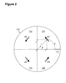
- Figure 2 is a schematic illustration of a cross section of a monolithic layer of birefringent material, defining a fast-axis orientation, a reference axis, and location coordinates;
- the present invention provides a depolarizer including a patterned half wave plate 100.
- the patterned half wave plate 100 has an entry surface 110 and an exit surface 120, and includes a monolithic layer 130 of birefringent material.
- the patterned half wave plate 100 may consist of a monolithic layer 130 of birefringent material, or may also include an optional photo-alignment layer 140, which may be adjacent to the entry surface 110 or the exit surface 120.
- the ideal thickness d of the patterned half wave plate 100 may be determined, as described above, on the basis of the average wavelength ⁇ of the incident light beam 150 and the birefringence ⁇ n of the birefringent material of the monolithic layer 130.
- the incident light beam 150 may be linearly or elliptically polarized and, preferably, has an average wavelength of about 400 to 2000 nm.
- the birefringent material preferably, has a birefringence of about 0.05 to 0.5.
- the actual thickness of the monolithic layer 130 is, preferably, close to the ideal value (within about 10 %).
- the entry surface 110 and the exit surface 120 of the half wave plate 100 are, preferably, substantially planar.
- the polarized light beam 150 launched into the entry surface 110, via an input port (not shown) and optional optical elements (such as a collimating lens; not shown) is, preferably, normal to the entry surface 110. Accordingly, the light beam 160 exiting the half wave plate 100 is made up of a plurality of different polarization states. When these polarization states are superpositioned at an image plane 170 of an optical system, via a focusing lens 180 and optional optical elements (not shown), the image 190 will be substantially depolarized.
- the patterned half wave plate 100 incorporates a monolithic layer 130 including a plurality of regions having fast axes with different orientations.
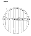
- the monolithic layer 130 may comprise a plurality of circular sectors or a plurality of parallel sections having different fast-axis orientations.
- the orientation 201 of each fast axis is characterized by an in-plane angle ⁇ within a range of 0 to 360° with respect to a reference axis 210 within a cross section of the monolithic layer 130 parallel to the entry surface 110; the positive angle direction is defined as counterclockwise.
- the monolithic layer 130 illustrated in Figure 2 has four regions 231, 232, 233, and 234 (each a circular sector) having four different fast-axis orientations 201, 202, 203, and 204.
- the fast axes have at least four different orientations within a cross section of the monolithic layer 130 parallel to the entry surface 110.
- the fast axes have at least eight different orientations.
- the fast axes may have as many as 48 or more different orientations.
- the orientations of the fast axes may vary continuously. Such a continuous variation of fast-axis orientation may be advantageous to reduce unwanted diffraction effects.
- the orientations of the fast axes vary in a regular pattern.
- the pattern may arise from a linear variation of the in-plane angle with respect to a location coordinate within a cross section of the monolithic layer 130 parallel to the entry surface 110.
- the location coordinate may be a polar coordinate, i.e. a radial coordinate r or an azimuthal angle ⁇ ; the azimuthal angle is defined as a counterclockwise angle from the reference axis 210.
- the in-plane angle may vary linearly with respect to a Cartesian coordinate, i.e. an x or y coordinate, within a cross section of the monolithic layer 130 parallel to the entry surface 110, as shown in Figure 2; the x axis is equivalent to the reference axis 210, and the length of the x axis is normalized to 1.
- the illustrated monolithic layer 130 includes 17 regions 431, 432, 433, 434, 435, 436, 437, 438, 439, 440, 441, 442, 443, 445, 446, and 447 (each a parallel section) having eight different fast-axis orientations 401, 402, 403, 404, 405, 406, 407, and 408.
- the device acts as spatial depolarizer that converts a polarized light beam 150 into a light beam 160 having a plurality of different polarization states within its cross section. If the incident light beam 150 is linearly polarized, the exiting light beam 160 will consist of a plurality of linearly polarized states. If the incident light beam 150 is elliptically polarized, the exiting light beam 160 will consist of a plurality of elliptically polarized states. If the incident light beam 150 is depolarized, the exiting light beam 160 will also be depolarized. Therefore, a partially polarized light beam 150 may also be depolarized by the patterned half wave plate 100.
- the patterned half wave plate 100 may be fabricated using a photo-alignment method, with ultraviolet (UV) light, that is similar to the methods disclosed in U. S. Patent No. 5,861,931 to Gillian, et al. , U. S. Patent No. 6,055,103 to Woodgate, et al. , U. S. Patent No. 7,061,561 to Silverstein, et al. , and a paper entitled " Photo-Aligned Anisotropic Optical Thin Films" by Seiberle, et al. (SID International Symposium Digest of Technical Papers, 2003, Vol. 34, pp. 1162-1165 ), for instance. All the above-mentioned documents are incorporated herein by reference.
- UV ultraviolet
- a photo-alignment layer 140 is created, as part of the patterned half wave plate 100.
- a photo-polymerizable material is applied to a substrate, typically a glass plate.
- the photo-polymerizable material is then irradiated with linearly polarized UV light to provide a directional alignment within the resulting photo-alignment layer 140.
- a photo-polymerizable prepolymer is used as the photo-polymerizable material, and the resulting photo-alignment layer 140 is composed of a photo-polymerizable polymer.
- a cross-linkable material is applied over the photo-alignment layer 140 and is aligned according to the directional alignment of the photo-alignment layer 140.
- the cross-linkable material is then cross-linked through exposure to UV light to produce the monolithic layer 130 of birefringent material, as part of the patterned half wave plate 100.
- a liquid-crystal prepolymer is used as the cross-linkable material, and the resulting monolithic layer 130 of birefringent material is composed of a liquid-crystal polymer.
- Suitable photo-polymerizable prepolymers and liquid-crystal prepolymers are available from Rolic Technologies Ltd. (Allschwil, Switzerland).
- An alignment pattern may be formed in the photo-alignment layer 140 by varying the polarization state of the linearly polarized UV light in a pattern during the creation of the layer. As discussed by Seiberle, et al., such alignment patterns may be generated by using photomasks, alignment masters, laser scanning, or synchronized movement of the linearly polarized UV light beam and the substrate. After application of the cross-linkable material onto the photo-alignment layer 140 and subsequent cross-linking, the resulting monolithic layer 130 of birefringent material will have fast axes with orientations that vary in a pattern corresponding to the alignment pattern.
- the monolithic layer 130 which includes a plurality of regions with different fast-axis orientations, may be produced from a photo-alignment layer 140 created by a series of exposures of the photo-polymerizable material to linearly polarized UV light through an appropriate number of patterned photomasks.
- a continuous variation of fast-axis orientation within the monolithic layer 130 may be achieved by using a photo-alignment layer 140 created by exposing the photo-polymerizable material to linearly polarized UV light through a slit, while moving the substrate in an appropriate pattern.
Applications Claiming Priority (1)
| Application Number | Priority Date | Filing Date | Title |
|---|---|---|---|
| US82355906P | 2006-08-25 | 2006-08-25 |
Publications (1)
| Publication Number | Publication Date |
|---|---|
| EP1892544A1 true EP1892544A1 (de) | 2008-02-27 |
Family
ID=38617220
Family Applications (1)
| Application Number | Title | Priority Date | Filing Date |
|---|---|---|---|
| EP07253361A Withdrawn EP1892544A1 (de) | 2006-08-25 | 2007-08-24 | Passiver Depolarisator |
Country Status (4)
| Country | Link |
|---|---|
| US (1) | US20080049321A1 (de) |
| EP (1) | EP1892544A1 (de) |
| JP (1) | JP2008070870A (de) |
| CN (1) | CN101131445A (de) |
Cited By (2)
| Publication number | Priority date | Publication date | Assignee | Title |
|---|---|---|---|---|
| CN102455522A (zh) * | 2010-10-15 | 2012-05-16 | 香港科技大学 | 图案化偏振转换器 |
| GB2527783A (en) * | 2014-07-01 | 2016-01-06 | Univ Leiden | A broadband linear polarization scrambler |
Families Citing this family (14)
| Publication number | Priority date | Publication date | Assignee | Title |
|---|---|---|---|---|
| US20080151245A1 (en) * | 2006-12-04 | 2008-06-26 | Carl Zeiss Smt Ag | method and a device for processing birefringent and/or optically active materials and phase plate |
| WO2008098144A1 (en) * | 2007-02-07 | 2008-08-14 | Baer Stephen C | Forming ligth beams and patterns with zero intensity central points |
| JP5061400B2 (ja) * | 2008-01-09 | 2012-10-31 | 富士フイルム株式会社 | 光学デバイス |
| US8040510B2 (en) * | 2008-08-22 | 2011-10-18 | Novasolar Holdings Limited | Spatially precise optical treatment or measurement of targets through intervening birefringent layers |
| DK2163923T3 (en) * | 2008-09-12 | 2015-02-09 | Jds Uniphase Corp | Optiskhvirvel-delaying microarray |
| TWI386722B (zh) * | 2008-10-24 | 2013-02-21 | Taiwan Tft Lcd Ass | 光學片、顯示裝置及其製作方法 |
| EP2284581A1 (de) * | 2009-08-07 | 2011-02-16 | JDS Uniphase Corporation | LC-Schichten mit räumlich variierendem Neigungswinkel |
| JP5751098B2 (ja) * | 2010-09-08 | 2015-07-22 | 旭硝子株式会社 | 投射型表示装置 |
| JP2012194221A (ja) * | 2011-03-15 | 2012-10-11 | Asahi Glass Co Ltd | 偏光解消素子および投射型表示装置 |
| CN102480058B (zh) * | 2011-03-31 | 2013-04-24 | 深圳光启高等理工研究院 | 一种基于超材料的去极化器 |
| JP5825161B2 (ja) | 2012-03-16 | 2015-12-02 | 旭硝子株式会社 | 走査型表示装置 |
| JP6104087B2 (ja) * | 2013-07-29 | 2017-03-29 | リコーインダストリアルソリューションズ株式会社 | 偏光解消素子及び偏光解消装置 |
| WO2016040890A1 (en) * | 2014-09-12 | 2016-03-17 | Thorlabs, Inc. | Depolarizers and methods of making thereof |
| JP2018072570A (ja) * | 2016-10-28 | 2018-05-10 | リコーインダストリアルソリューションズ株式会社 | スペックル解消素子及びスペックル解消機構 |
Citations (9)
| Publication number | Priority date | Publication date | Assignee | Title |
|---|---|---|---|---|
| US5861931A (en) | 1995-10-13 | 1999-01-19 | Sharp Kabushiki Kaisha | Patterned polarization-rotating optical element and method of making the same, and 3D display |
| US6055103A (en) | 1997-06-28 | 2000-04-25 | Sharp Kabushiki Kaisha | Passive polarisation modulating optical element and method of making such an element |
| US6266109B1 (en) * | 1997-10-16 | 2001-07-24 | Kabushiki Kaisha Toshiba | Liquid crystal optical switching element in which the liquid crystal material occupies more than 50% of the medium |
| US6300991B1 (en) * | 1995-07-28 | 2001-10-09 | Rolic Ag | Photo-oriented polymer network material having desired azimuthal orientation and tilt angle and method for its production |
| US20040080754A1 (en) * | 2002-10-29 | 2004-04-29 | Mitutoyo Corporation | Interferometer using integrated imaging array and high-density phase-shifting array |
| US20040263974A1 (en) * | 2003-06-26 | 2004-12-30 | Optical Coating Laboratory Inc., A Jds Unipahse Company And A Corporation Of The State Of Delware | Flat polarization conversion system with patterned retarder |
| US6885502B2 (en) * | 1995-09-23 | 2005-04-26 | Carl-Zeiss-Stiftung | Radial polarization-rotating optical arrangement and microlithographic projection exposure system incorporating said arrangement |
| EP1542065A1 (de) * | 2003-12-11 | 2005-06-15 | JDS Uniphase Corporation | Polarisationssteuerelemente |
| US7061561B2 (en) | 2002-01-07 | 2006-06-13 | Moxtek, Inc. | System for creating a patterned polarization compensator |
Family Cites Families (19)
| Publication number | Priority date | Publication date | Assignee | Title |
|---|---|---|---|---|
| US2473857A (en) * | 1946-12-05 | 1949-06-21 | Burchell Holloway Corp | Apparatus for insertion in color display devices utilizing polarized light for securing changing saturation of specific hues in fixed zones as vewed by observers |
| US3617934A (en) * | 1969-09-02 | 1971-11-02 | Joseph P Segre | Conversion of tangential and radial polarization components to rectangular coordinate components |
| US4198123A (en) * | 1977-03-23 | 1980-04-15 | Baxter Travenol Laboratories, Inc. | Optical scrambler for depolarizing light |
| US5028134A (en) * | 1990-05-24 | 1991-07-02 | Kollmorgen Instruments | Depolarizer for light measuring instruments |
| GB2286058A (en) * | 1994-01-21 | 1995-08-02 | Sharp Kk | Switchable holographic apparatus |
| US6498869B1 (en) * | 1999-06-14 | 2002-12-24 | Xiaotian Steve Yao | Devices for depolarizing polarized light |
| US7099081B2 (en) * | 2000-08-18 | 2006-08-29 | Tokyo Electron Limited | Small-spot spectrometry instrument with reduced polarization and multiple-element depolarizer therefor |
| AU2001287190A1 (en) * | 2000-08-18 | 2002-03-04 | Sensys Instruments Corporation | Small-spot spectrometry instrument with reduced polarization |
| US6630289B1 (en) * | 2000-08-22 | 2003-10-07 | The Hong Kong University Of Science And Technology | Photo-patterned light polarizing films |
| US7053988B2 (en) * | 2001-05-22 | 2006-05-30 | Carl Zeiss Smt Ag. | Optically polarizing retardation arrangement, and microlithography projection exposure machine |
| JP4340833B2 (ja) * | 2001-06-08 | 2009-10-07 | 横河電機株式会社 | 偏光解消板及び偏光解消板を用いた光学装置 |
| US6909473B2 (en) * | 2002-01-07 | 2005-06-21 | Eastman Kodak Company | Display apparatus and method |
| US6841320B2 (en) * | 2002-02-06 | 2005-01-11 | Optiva, Inc. | Method of fabricating anisotropic crystal film on a receptor plate via transfer from the donor plate, the donor plate and the method of its fabrication |
| US6819810B1 (en) * | 2002-04-09 | 2004-11-16 | Oplink Communications, Inc. | Depolarizer |
| TWI385414B (zh) * | 2003-11-20 | 2013-02-11 | 尼康股份有限公司 | 光學照明裝置、照明方法、曝光裝置、曝光方法以及元件製造方法 |
| US7548370B2 (en) * | 2004-06-29 | 2009-06-16 | Asml Holding N.V. | Layered structure for a tile wave plate assembly |
| JP4715171B2 (ja) * | 2004-11-19 | 2011-07-06 | 旭硝子株式会社 | 半導体レーザモジュール及びラマン増幅器 |
| US20080137189A1 (en) * | 2006-12-12 | 2008-06-12 | Northrop Grumman Space & Mission Systems Corporation | Conversion of the polarization of light via a composite half-wave plate |
| US7715099B2 (en) * | 2006-12-12 | 2010-05-11 | Northrop Grumman Space & Mission Systems Corporation | Optical birefringence coronagraph |
-
2007
- 2007-08-24 CN CNA2007101475421A patent/CN101131445A/zh active Pending
- 2007-08-24 US US11/844,428 patent/US20080049321A1/en not_active Abandoned
- 2007-08-24 JP JP2007218782A patent/JP2008070870A/ja active Pending
- 2007-08-24 EP EP07253361A patent/EP1892544A1/de not_active Withdrawn
Patent Citations (9)
| Publication number | Priority date | Publication date | Assignee | Title |
|---|---|---|---|---|
| US6300991B1 (en) * | 1995-07-28 | 2001-10-09 | Rolic Ag | Photo-oriented polymer network material having desired azimuthal orientation and tilt angle and method for its production |
| US6885502B2 (en) * | 1995-09-23 | 2005-04-26 | Carl-Zeiss-Stiftung | Radial polarization-rotating optical arrangement and microlithographic projection exposure system incorporating said arrangement |
| US5861931A (en) | 1995-10-13 | 1999-01-19 | Sharp Kabushiki Kaisha | Patterned polarization-rotating optical element and method of making the same, and 3D display |
| US6055103A (en) | 1997-06-28 | 2000-04-25 | Sharp Kabushiki Kaisha | Passive polarisation modulating optical element and method of making such an element |
| US6266109B1 (en) * | 1997-10-16 | 2001-07-24 | Kabushiki Kaisha Toshiba | Liquid crystal optical switching element in which the liquid crystal material occupies more than 50% of the medium |
| US7061561B2 (en) | 2002-01-07 | 2006-06-13 | Moxtek, Inc. | System for creating a patterned polarization compensator |
| US20040080754A1 (en) * | 2002-10-29 | 2004-04-29 | Mitutoyo Corporation | Interferometer using integrated imaging array and high-density phase-shifting array |
| US20040263974A1 (en) * | 2003-06-26 | 2004-12-30 | Optical Coating Laboratory Inc., A Jds Unipahse Company And A Corporation Of The State Of Delware | Flat polarization conversion system with patterned retarder |
| EP1542065A1 (de) * | 2003-12-11 | 2005-06-15 | JDS Uniphase Corporation | Polarisationssteuerelemente |
Non-Patent Citations (2)
| Title |
|---|
| SEIBERLE ET AL.: "Photo-Aligned Anisotropic Optical Thin Films", SID INTERNATIONAL SYMPOSIUM DIGEST OF TECHNICAL PAPERS, vol. 34, 2003, pages 1162 - 1165 |
| SEIBERLE H. ET AL.: "Photo-Aligned Anisotropic Optical Thin Films", CONFERENCE PROCEEDINGS ARTICLE, vol. XXXIV, 2003, International Symposium Digest of Technical Papers, pages 1162 - 1165, XP007008324 * |
Cited By (3)
| Publication number | Priority date | Publication date | Assignee | Title |
|---|---|---|---|---|
| CN102455522A (zh) * | 2010-10-15 | 2012-05-16 | 香港科技大学 | 图案化偏振转换器 |
| CN102455522B (zh) * | 2010-10-15 | 2014-11-12 | 香港科技大学 | 图案化偏振转换器 |
| GB2527783A (en) * | 2014-07-01 | 2016-01-06 | Univ Leiden | A broadband linear polarization scrambler |
Also Published As
| Publication number | Publication date |
|---|---|
| US20080049321A1 (en) | 2008-02-28 |
| CN101131445A (zh) | 2008-02-27 |
| JP2008070870A (ja) | 2008-03-27 |
Similar Documents
| Publication | Publication Date | Title |
|---|---|---|
| EP1892544A1 (de) | Passiver Depolarisator | |
| US9715048B2 (en) | Broadband optics for manipulating light beams and images | |
| EP3123215B1 (de) | Bragg-flüssigkristallpolarisationsgitter | |
| KR101919646B1 (ko) | 광대역 편광 변환을 위한 멀티 트위스트 지연기 및 관련 제조 방법 | |
| EP2906974B1 (de) | Direktbeschreibbare lithografie zur herstellung von geometrischen phasenhologrammen | |
| Escuti et al. | Simplified spectropolarimetry using reactive mesogen polarization gratings | |
| JP5462783B2 (ja) | 低ツイストキラル液晶偏光回折格子および関連する作製方法 | |
| US8982313B2 (en) | Beam steering devices including stacked liquid crystal polarization gratings and related methods of operation | |
| KR101871345B1 (ko) | 복소 정보를 갖는 파동장을 변조하는 공간 광변조 장치 | |
| JP2009151287A (ja) | 光の偏光の空間分布の色収差補正コンバータ | |
| Kim et al. | Demonstration of large-angle nonmechanical laser beam steering based on LC polymer polarization gratings | |
| WO2006023528A2 (en) | Tunable spectral imaging filter configured for uv spectral ranges | |
| Sakhno et al. | Fabrication and performance of efficient thin circular polarization gratings with Bragg properties using bulk photo-alignment of a liquid crystalline polymer | |
| US20210389513A1 (en) | Liquid crystal optical element and fabrication method thereof | |
| Kawai et al. | Tunable dichroic polarization beam splitter created by one-step holographic photoalignment using four-beam polarization interferometry | |
| WO2016001173A1 (en) | A broadband linear polarization scrambler | |
| CN101178485A (zh) | 电控焦移的超分辨光瞳滤波器 | |
| Kim et al. | A compact holographic recording setup for tuning pitch using polarizing prisms | |
| Ma et al. | Optical design of multilayer achromatic waveplate by simulated annealing algorithm | |
| AU2015411341B2 (en) | Optical element and production method with multiple latent images for document security | |
| EP1924878B1 (de) | Optisches element und herstellungsverfahren | |
| Kim | Liquid crystal geometric phase holograms for efficient beam steering and imaging spectropolarimetry | |
| JPH0764033A (ja) | 光入力装置 | |
| Tabirian et al. | High efficiency broadband liquid crystal polymer vector vortex waveplates | |
| Nersisyan et al. | Vector vortex waveplates with tunable spectrum and switchable topological charge |
Legal Events
| Date | Code | Title | Description |
|---|---|---|---|
| PUAI | Public reference made under article 153(3) epc to a published international application that has entered the european phase |
Free format text: ORIGINAL CODE: 0009012 |
|
| AK | Designated contracting states |
Kind code of ref document: A1 Designated state(s): AT BE BG CH CY CZ DE DK EE ES FI FR GB GR HU IE IS IT LI LT LU LV MC MT NL PL PT RO SE SI SK TR |
|
| AX | Request for extension of the european patent |
Extension state: AL BA HR MK YU |
|
| 17P | Request for examination filed |
Effective date: 20080711 |
|
| 17Q | First examination report despatched |
Effective date: 20080807 |
|
| AKX | Designation fees paid |
Designated state(s): AT BE BG CH CY CZ DE DK EE ES FI FR GB GR HU IE IS IT LI LT LU LV MC MT NL PL PT RO SE SI SK TR |
|
| GRAP | Despatch of communication of intention to grant a patent |
Free format text: ORIGINAL CODE: EPIDOSNIGR1 |
|
| STAA | Information on the status of an ep patent application or granted ep patent |
Free format text: STATUS: THE APPLICATION IS DEEMED TO BE WITHDRAWN |
|
| 18D | Application deemed to be withdrawn |
Effective date: 20111111 |